
Related Manuals for micro-trak MT-9000 FTW


Summary of Contents for micro-trak MT-9000 FTW
- Page 1 MT-9000 Automatic Spray Rate Controller Reference Manual *For Hardi sprayers and other sprayers equipped with a single flowmeter and three-way shut-off valves.
- Page 2 The MT-9000 FTW has been designed for easy installation and op er a tion. How ev er, since each in stal la tion will vary depending on your equipment, please take time to fa mil iar ize yourself with this manual and the actual components before beginning.
-
Page 3: Warranty
Registration card information is for internal use only. * Some limitations apply. See warranty statement for details. At Micro-Trak Systems, we believe a product that delivers quality and performance at a low cost is what is needed to help today’s operator and the operator of the future. -
Page 4: Table Of Contents
Table of Contents Warranty...................................... 3 Table of Contents ...................................4-5 Introduction ....................................6 Basic Overview of Typical Installation ..........................7 Component Parts and Assembly Hardware ........................8-9 Installation ..................................10-20 Required Tools ......................................10 Mounting the Display Console ................................10 Electrical Installation ....................................10 Speed Sensor Installation ................................11-12 Magnets ......................................11 Attaching Magnets .................................. -
Page 5: Table Of Contents
Table of Contents (cont) Operation .................................... 33-36 Display Area, Power Switch, Auto/Man/Hold Switch, “+/- Switch, Boom Switches ............33 Rate Buttons, Tank Button, Alarm Switch, Test Button, Reset Button, DB-9 Connector ..........34 Rotary Dial ........................................35 Warning Device, Light Sensor, Variable Rate Technology ....................... 35 Version/Hour Display on Startup ............................... -
Page 6: Introduction
Introduction MT-9000 FTW System RS-232 SERIAL INTERFACE The MT-9000 FTW is a flow-based control system which is designed to be used on Hardi sprayers and other sprayers The MT-9000 serial interface allows the MT-9000 to be equipped with diverting (three-way) boom valves. -
Page 7: Basic Overview Of Typical Installation
Basic Overview of Typ i cal Installation Hall-E ect Speed Sensor (or Vansco or Optional Radar or GPS Speed Sensor) Magnets on Hub of Non-driven Wheel Local Access MT-9000 Console Speed Connection Battery Main Harness Hitch Connection Rear Speed Connection NH3500 Kit or Liqui er Kit Nurse... -
Page 8: Component Parts And Assembly Hardware
MT-9000 Automatic Spray Rate Controller Reference Manual *For Hardi sprayers and other sprayers equipped with a single owmeter and three-way shut-o valves. MT-9000 FTW Console Reference Manual Console Mount Kit P/N 13956 P/N 13953 P/N 13254 20’ 3-Pin M/P Power Harness 5’... - Page 9 Component Parts and Assembly Hardware (cont) Before beginning installation, check the carton contents for the following items: Red Tie Flow (Green Tie) Boom 1 (Brown Tie) Run/Hold (Gray Tie) Servo (No Tie) 5’ Relief, Booms 2-3, Pressure Harness P/N 13084 White Tie Natural Tie (Natural)
-
Page 10: Installation
Illustration 3. Be sure there is good metal-to-metal con tact. (black) Your MT-9000 FTW is equipped with an elec tronic mem o ry which does not re quire a con stant supply of pow er to re tain daily totals or calibration val ues. The advantage with this type of memory is that it conserves battery power and will not dis charge the vehicle’s battery when equipment is not... -
Page 11: Speed Sensor Installation
6. For this example, the minimum number of magnets required is 6. The magnets provided by Micro-Trak are marked with a punched dashed line on the SOUTH pole side of the magnet. English or Turf (inches) See Illustration 4. -
Page 12: Attaching Speed Sensor
45° max is sent to the MT-9000 FTW console every time a magnet passes by the tip of the speed sensor. For the speed sensor 3/8” nuts to operate properly, the spacing between the magnets and the tip of the sensor must always remain constant. -
Page 13: Connecting The Run/Hold Sensor Cable
SkyTrak or Dickey-John Vansco Radar Speed Sensor GPS speed sensors. An adapter cable may be required. Contact a Micro-Trak sales representative for de tails on any of these products, or call Mi cro-Trak Systems, Inc. at 1-800-328-9613. -
Page 14: Mounting And Plumbing Flowmeter
Installation (cont) Mounting and Plumbing Flowmeter Illustration 10 The flowmeter must be installed at the pump output after any Hose Clamps* Sprayer Line* strainers, return lines, or valves. Securely mount flowmeter ¾” NPT Male Fitting* (hardware not supplied) in a vertical position in an area away from intense vibration. -
Page 15: Pressure Relief Valve
Installation (cont) Illustration 12 Pressure Relief Valve Pressure If you have a positive displacement pump or a centrifugal Relief Valve pump capable of generating excessive pressure, you Tee “C” must install a pressure relief valve and adjust it to a safe maximum pressure. -
Page 16: Servo, Throttling Valves
Installation (cont) Servo, Throttling Valves The servo valve installs in an unrestricted return line to the Illustration 15 inlet of the pump or directly into the tank. DO NOT install the From Pump servo valve closer than 12” to the flowmeter. The servo valve Throttling Valve has a flow direction decal on it. -
Page 17: Boom Shut-Off Valves
Installation (cont) Boom Shut-off Valves Locate the boom shut-off cables. Crimp the insulated quick Illustration 17 Return Line disconnect terminals provided with the cables to both wires. to Tank (If valves have wires, crimp terminals on those wires.) Attach the cables to the terminals on the boom valves. Normally, wires connect red to red and black to black. -
Page 18: Plumbing Overview Diagram
Installation (cont) MT-9000 FTW Plumbing Overview Diagram... -
Page 19: Valve Diagrams
Installation (cont) MT-9000 Series Plumbing Valve Overview Range For Oversized Pumps Adjust Valve Tee “C” Tee “A” For Positive Displacement Pumps Pressure Relief Valve Tee “C” Tee “A” If Optional Relief Valve Kit is Used Servo Valve Relief Valve Tee “B”... -
Page 20: Wiring Diagram
Installation (cont) MT-9000 Series Wiring Diagram MT 9000 SERIES CONSOLE 3-PIN METRI-PAK630 10-PIN METRI-PACK TOWER SHROUD 10-PIN METRI-PACK TOWER 10-PIN METRI-PACK SHROUD 10-PIN METRI-PACK TOWER 10-PIN METRI-PACK SHROUD 3-PIN 10-PIN METRI-PACK SHROUD METRI-PAK630 TOWER 10-PIN METRI-PACK TOWER 10-PIN METRI-PACK SHROUD 10-PIN METRI-PACK TOWER 10-PIN METRI-PACK SHROUD 10-PIN METRI-PACK TOWER... -
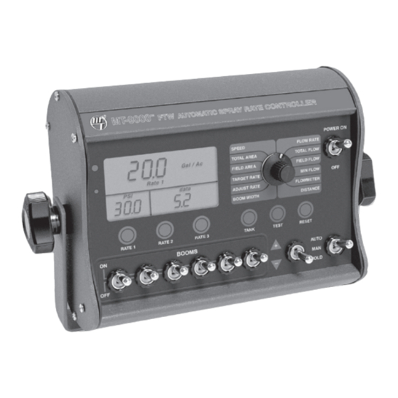
Page 21: Console Functions
Console Functions - MT-9000 Series The MT-9000 Series features a large, easy-to-read display with bold, heavy duty buttons and toggle switches, and a rugged outer case. OPERATION POSITIONS RATE 1, 2, 3: When pressed, displays a preset application The MT-9000 Series offers two different Operation positions: rate. -
Page 22: Calibration
Utility Software also provides the ability to download before you get to the field. and store all of the data collected by the MT-9000 FTW, or to reprogram the MT-9000 FTW with program upgrade files A Software Utility package is provided with each system. -
Page 23: Units Of Measure, Servo Type, Servo Polarity
“12” for servo valves from BOOM WIDTH other manufacturers. NOTE: Do not attempt to use a “12” setting with a Micro-Trak servo valve. Damage due to over-voltage will not be covered under warranty. SERVO POLARITY: This “Special Cal” position is used... -
Page 24: Boom Shut-Off Valve Type, Tank Alarm Set Point, Tank Size
FLOWMETER valves that require voltage reversing. See Appendix B for other configurations. If you need assistance for wiring other than shown in Appendix B, contact Micro-Trak for instructions. TANK ALARM SET POINT: This “Special Cal” position Display will Read... -
Page 25: Standard Calibration
Standard Calibration General Illustration 19 MT-9000 SERIES FTW AUTOMATIC SPRAY RATE CONTROLLER Once in calibration mode, you may change any one, all or none of the values, in any order. To enter calibration mode, simply turn the rotary selector to the desired calibration POWER ON Gal / 1000 FLOW RATE... -
Page 26: Boom Width, Setting Individual Boom Width, Banding Application Calibration
Standard Calibration (cont) Entering Standard Calibration Values (cont) BOOM WIDTH: Enter the working width, in inches (meters), Display will Read for the boom section currently shown on the Gal / 1000 display. Use the “+/—” switch to adjust the Lbs N / Ac displayed value to the correct width for the Gal / Ac kg / ha... -
Page 27: Flowmeter, Distance
(0.0) as the flowmeter calibration value. Your Micro-Trak flowmeter has been tested at the factory and Illustration 20 assigned a “Flowmeter” calibration value to make it operate properly with the MT-9000 FTW console. This number is stamped on the metal tag attached to the flowmeter. -
Page 28: Pressure Offset
Standard Calibration (cont) Pressure Offset If your system is using an electronic pressure sensor, you must null the pressure offset. This procedure sets the zero point of the sensor. Until the pressure offset is nulled, the pressure display will be blank. TO NULL THE PRESSURE SENSOR Make sure the pressure sensor is installed with ZERO pressure (no pressure) present. -
Page 29: Fine-Tuning Speed/Distance Calibration
Standard Calibration (cont) Fine-Tuning Speed/Distance Calibration Value This procedure is used to verify the calibration of the system. Toggle the “+/—” switch to adjust the upper display In order to achieve accurate measurements, each step in this until it matches the actual distance traveled. This will fine tuning procedure should be performed as precisely as also fine-tune the Distance Cal factor in the lower right possible. -
Page 30: Fine-Tuning Flowmeter Calibration
Standard Calibration (cont) Fine-Tuning Flowmeter Calibration This procedure is used to verify and fine-tune the flowmeter To verify proper calibration, repeat the procedure a second calibration. Every flowmeter is calibrated with water at the time. Write down the new Flowmeter Calibration value factory and stamped with a calibration value. -
Page 31: Standard Factory-Loaded Calibration
When a typical operating Turn the rotary switch to the SPEED position. speed is entered, the MT-9000 FTW will respond as if Put the AUTO/MAN/HOLD switch in HOLD. you were actually driving that speed. It allows you to simulate your spraying application with plain water, while remaining Hold the appropriate RATE key and the “+”... -
Page 32: Pre-Field System Checkout
PSI may be slightly higher than indicated by the charts due MT-9000 FTW to provide the required application control. to pressure drop across the solenoid valve, nozzle diaphragm This procedure should be repeated for each new nozzle check valve, nozzle screens, etc. -
Page 33: Operation
Operation Switches and Buttons DISPLAY AREA During normal operation, when the AUTO/ MAN/HOLD switch is in MAN, the application rate will not be maintained by the During normal operation, the console will always display console automatically. For example, The MAN position may pressure in the lower left corner of the display (if installed), be used by the operator to do things such as spot spraying, application rate in the upper half of the display and the... -
Page 34: Rate Buttons, Tank Button, Alarm Switch, Test Button, Reset Button, Db-9 Connector
AUDIBLE ALARM The Rate buttons serve many functions within the system, The MT-9000 FTW consoles have an audible alarm that will and can be used within Calibration and Operation (AUTO sound when the application rate exceeds +/- 10% of the and MAN). -
Page 35: Rotary Dial
Operation (cont) Rotary Dial Warning Device During normal operation, you can view any one of six monitored functions in the lower right portion of the display The console is equipped with a RED warning light. The (data window) by turning the rotary dial to the appropriate light will automatically turn on and flash when the actual position. -
Page 36: Version/Hour Display On Startup
Illustration 24 Version/Hour Display on Start-up MT-9000 SERIES MT-9000 SERIES FTW AUTOMATIC SPRAY RATE CONTROLLER On start-up, the MT-9000 FTW console briefly (approximately three seconds) allows the operator to view the amount of POWER ON Gal / 1000 FLOW RATE... -
Page 37: Troubleshooting
If you have a two-way radio, it may be mounted too close Implement width or wheel circumference was measured to the console. Keep all MT-9000 FTW cables away from the incorrectly or programmed incorrectly. Go back through radio, its antenna and power cable. -
Page 38: Checking Individual Components
Troubleshooting Checking Individual Components CONSOLE RUN/HOLD JUMPER DUST COVER The only way to field test a console is to connect it to a To test for proper continuity on the jumper wire, connect the harness on a vehicle with a known working console or install ohmmeter to the pins of the dust cover with the jumper wire. -
Page 39: Checking Console Inputs
Troubleshooting FLOWMETER Shaking the flowmeter end to end should produce a “rattling” Console Inputs sound (shaft end play). Blowing in the meter from either end should spin the turbine freely. If the turbine spins freely but If there is no response from any of the following tests, refer the meter will not register flow with a known working sensor, to the main wiring diagram on page 19 to locate the next the turbine may be defective. -
Page 40: Plumbing Troubleshooting Chart
PRESSURE SENSOR Proper plumbing is a very important factor in obtaining optimal performance from your MT-9000 FTW system. The The only way to field test the pressure sensor is to connect chart on the following page will help you determine what it to a known working console, apply pressure and verify the area of the plumbing may be causing your problem. -
Page 41: Plumbing Guidelines
Plumbing Guidelines General PUMP In order for your sprayer to function properly, it must be correctly plumbed. This section will explain the purpose The pump must have enough capacity to satisfy the agitation, of each component, list some problems it can cause and servo and flowmeter sections of the plumbing. -
Page 42: Valve Purpose And Adjustments
Plumbing Guidelines Valve Purpose and Adjustments TANK SHUT-OFF VALVE THROTTLE VALVE The tank shut-off is for convenience only. It allows you to The throttle valve limits your high end to maximize servo work on the plumbing without draining the tank. It should performance. -
Page 43: Appendices
Appendices... -
Page 44: Appendix A: Optional Speed Sensor Mounting Installation
Appendix A Speed Sensor and Bracket Optional Speed Sensor Installation IMPLEMENT WHEELS ¼” Bolts, Lockwashers Prepare and install magnet clips as shown. and Nuts Place a magnet at the end of each clip (longest side of Speed Sensor magnet should point in the direction of wheel rotation). Rigidly mount sensor mounting bracket to the wheel assembly. - Page 45 Hall-effect speed sen sor must alternate as is set, tight en nuts to lock sensor in place. the shaft is turned. The magnets provided by Micro-Trak are • Secure sensor cable to frame with cable ties. Place first tie marked with a punched dashed line on the SOUTH pole side as close to sensor assembly as possible.
-
Page 46: Appendix B: Various Ball Valve Configurations
Appendix B Various Ball Valve Configurations Some basic 2, 3 & 4-wire configurations are shown below. If you need assistance for wiring other than shown, contact Micro-Trak for wiring instructions. 2-Wire Valve Micro-Trak Boom Connection Switching Wires* Valve (Set for Ball Valve) -
Page 47: Appendix C Adjusting By-Pass Valves
Appendix C Adjusting By-Pass Valves The following is a basic procedure for adjusting the by-pass valves in a single flowmeter, three-way boom shut-off valve system. You may need to check your sprayer’s operating manual for more specific details. NOTE: This procedure is not intended to replace any sprayer manufacturer’s instructions. -
Page 48: Appendix D: Flowmeter Cleaning And Assembly
Appendix D Flowmeter Cleaning and Assembly NOTE: Opening the flowmeter will void the Flow Calibration NOTE: The turbines have magnets built into the fins. There value assigned to your unit. However, you may need are no visible magnets. to take the flowmeter apart for periodic cleaning or to On a flat surface, place each housing half on end. -
Page 49: Appendix E. Conversion Chart
Appendix E Conversion Chart English to Metric Metric to English When You Know Multiple By To Find When You Know Multiple By To Find LINEAR MEASUREMENT LINEAR MEASUREMENT inches 25.4 millimeters millimeters .039 inches feet 0.305 meters meters 3.28 feet yards 0.914 meters... -
Page 50: Appendix F: Replacement Parts List
Appendix F Flowmeter Replacement Parts List The following replacement parts are available from your dealer or distributor, or directly from: Micro-Trak Systems, Inc. P.O. Box 99, 111 East LeRay Avenue Eagle Lake, MN 56024-0099 When ordering parts, please list the model number of your console and the description and part number of each part that you want to order. -
Page 51: Appendix G Glossary Of Terms
Appendix G Glossary of Terms APPLICATION RATE: OUTPUT: An amount, unit or ratio of material The amount of material applied. being applied. PRESSURE-BASED CONTROL: Using information from ASTRO SERIES OF GPS BASED SPEED SENSORS: a pressure sensor to determine the amount of adjustment direct replacement for magnetic wheel speed sensors or required. - Page 52 MANUFACTURED IN THE U.S.A. BY 1305 Stadium Road, Mankato, MN 56001-5355 Toll Free: (800) 328-9613 • (507) 257-3600 www.micro-trak.com • trakmail@micro-trak.com © 2000 • Micro-Trak Systems, Inc. • Printed in U.S.A. • P/N 13953 Rev 2...
Need help?
Do you have a question about the MT-9000 FTW and is the answer not in the manual?
Questions and answers