
Subscribe to Our Youtube Channel
Related Manuals for IBASE Technology IB995


Summary of Contents for IBASE Technology IB995
- Page 1 IB995 8th or 9th Gen. Xeon. Core™ i7/i5/i3 ® Intel Full-Size CPU Card User’s Manual Version 1.0 (Oct. 2019)
- Page 2 No part of this publication may be reproduced, copied, stored in a retrieval system, translated into any language or transmitted in any form or by any means, electronic, mechanical, photocopying, or otherwise, without the prior written consent of IBASE Technology, Inc. (hereinafter referred to as “IBASE”). Disclaimer IBASE reserves the right to make changes and improvements to the products described in this document without prior notice.
-
Page 3: Compliance
0.1% by weight (1000 ppm) except for cadmium, limited to 0.01% by weight (100 ppm). • Lead (Pb) • Mercury (Hg) • Cadmium (Cd) • Hexavalent chromium (Cr6+) • Polybrominated biphenyls (PBB) • Polybrominated diphenyl ether (PBDE) IB995 User’s Manual... -
Page 4: Important Safety Information
Danger of explosion if the internal lithium-ion battery is replaced by an incorrect type. Replace only with the same or equivalent type recommended by the manufacturer. Dispose of used batteries according to the manufacturer’s instructions or recycle them at a local recycling facility or battery collection point. IB995 User’s Manual... -
Page 5: Warranty Policy
Software in use (such as OS and application software, including the version numbers) If repair service is required, you can download the RMA form at http://www.ibase.com.tw/english/Supports/RMAService/. Fill out the form and contact your distributor or sales representative. IB995 User’s Manual... -
Page 6: Table Of Contents
Installing the CPU ..............10 2.1.2 Installing the Memory ............11 Setting the Jumpers ................12 Jumper & Connector Locations on IB995 .......... 13 Jumpers Quick Reference ..............14 2.4.1 PCIe (x16) Bifurcation Selection (JP2 & JP3) ...... 15 2.4.2 LVDS Power Brightness Selection (JP4) ...... - Page 7 Parallel Port (J24) ..............29 Chapter 3 Drivers Installation ..........31 Introduction ..................32 ® Intel Chipset Software Installation Utility ...........33 VGA Driver Installation ...............35 HD Audio Driver Installation ...............38 LAN Driver Installation ...............39 ® Intel Management Engine Interface ..........42 IB995 User’s Manual...
- Page 8 Secure Boot Configuration ........... 66 4.6.1.1 Key Management ..............67 Boot Settings ..................69 Save & Exit Settings................70 Appendix ..................71 I/O Port Address Map ................ 72 Interrupt Request Lines (IRQ) ............73 Watchdog Timer Configuration ............74 IB995 User’s Manual viii...
-
Page 9: Chapter 1 General Information
Chapter 1 General Information The information provided in this chapter includes: • Features • Packing List • Optional Accessories • Block Diagram • Specifications • Board Overview • Board Dimensions... -
Page 10: Introduction
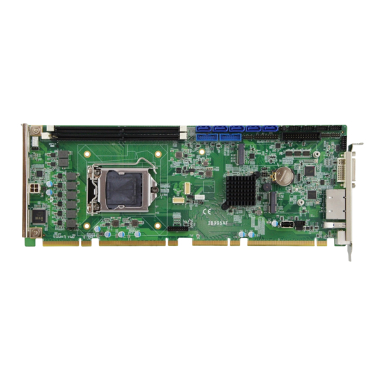
LVDS, DVI-I and DVI-D display outputs. IB995 utilizes the dramatic increase in performance provided by Intel’s latest cutting-edge technology. Measuring 338mm x122mm, IB995 offers fast 6Gbps SATA support (up to 8 ports), USB3.1 (5 ports) and interfaces for two Gigabit LAN. Photo of IB995 Features •... -
Page 11: Packing List
General Information Packing List Your IB995 package should include the items listed below. If any of the items is missing, please contact the distributor or dealer from whom you have purchased the product. • IB995AF PICMG1.3 SHB x 1 •... -
Page 12: Specifications
Yes (256 segments, 0, 1, 2…255 sec / min) Timer BIOS AMI BIOS iSmart RAID RAID 0/1/5 ® 11.6 (with E-Xeon / Core i7/ i5 iAMT DT CPU SKUs) Dimensions 338mm x 126mm RoHS Certification CE, FCC IB995 User’s Manual... - Page 13 • Operating: 0 ~ 60 °C (32 ~ 140 °F) Temperature • Storage: -20 ~ 80 °C (-4 ~ 176 °F) 0 ~ 90 %, non-condensing at 60 °C Relative Humidity All specifications are subject to change without prior notice. IB995 User’s Manual...
-
Page 14: Block Diagram
Block Diagram IB995 User’s Manual... -
Page 15: Board Pictures
General Information Board Pictures Top View Bottom View I/O View *The photos above are for reference only. IB995 User’s Manual... -
Page 16: Dimensions
Dimensions IB995 User’s Manual... -
Page 17: Chapter 2 Hardware Configuration
Hardware Configuration This section provides information on jumper settings and connectors on the IB995 in order to set up a workable system. On top of that, you will also need to install crucial pieces such as the CPU and the memory before using the product. The topics covered are: •... -
Page 18: Essential Installations Before You Begin
Essential Installations Before You Begin Follow the instructions below to install the CPU and the memory. 2.1.1 Installing the CPU The IB995 board supports an LGA1151 Socket (shown below) for ® ® ® Intel Xeon E3 v5 family or Intel Gen. -
Page 19: Installing The Memory
Hardware Configuration 2.1.2 Installing the Memory The IB995 board supports two DDR4 memory socket for a maximum total memory of 32GB in DDR4 UDIMM memory type. To install the modules, locate the memory slot on the board and perform the... -
Page 20: Setting The Jumpers
Setting the Jumpers Set up and configure your IB995 by using jumpers for various settings and features according to your needs and applications. Contact your supplier if you have doubts about the best configuration for your use. 2.2.1 How to Set Jumpers Jumpers are short-length conductors consisting of several metal pins with a non-conductive base mounted on the circuit board. -
Page 21: Jumper & Connector Locations On Ib995
Hardware Configuration Jumper & Connector Locations on IB995 Board diagram of IB995AF (for Q170) IB995 User’s Manual... -
Page 22: Jumpers Quick Reference
Jumpers Quick Reference Function Jumper Page PCIe Bifurcation Selection JP2, JP3 LVDS Panel Brightness Selection LVDS Panel Power Selection Clearing ME Register Clearing CMOS Data IB995 User’s Manual... -
Page 23: Pcie (X16) Bifurcation Selection (Jp2 & Jp3)
PCIe (x16) Bifurcation Selection (JP2 & JP3) Function Pin closed Illustration JP3: Open 1 x PCIe (x16) (default) JP2: Open JP3: Open 2 x PCIe (x8) JP2: Close JP3: Close 1 x PCIe (x8) 2 x PCIe (x4) JP2: Close IB995 User’s Manual... -
Page 24: Lvds Power Brightness Selection (Jp4)
2.4.2 LVDS Power Brightness Selection (JP4) Function Pin closed Illustration 3.3V (default) 2.4.3 LVDS Panel Power Selection (JP6) Function Pin closed Illustration 3.3V (default) IB995 User’s Manual... -
Page 25: Clearing Me Register (Jp8)
Hardware Configuration 2.4.4 Clearing ME Register (JP8) Function Pin closed Illustration Normal (default) Clear ME 2.4.5 Clearing CMOS Data (JP9) Function Pin closed Illustration Normal (default) Clear CMOS IB995 User’s Manual... -
Page 26: Connectors Quick Reference
Digital I/O Connector LCD Backlight Connector ATX 12V Power Connector Dual USB 3.0 Pin-Header J8,J9 Dual USB 2.0 Pin-Header Front Panel Audio Connector Front Panel Settings Connector LVDS Connector J11, J12 Fan Power Connector CPU_FAN1 DVI-D Connector Parallel Port IB995 User’s Manual... -
Page 27: Com1 Rs-232/422/485 & Com2 Rs-232 Serial Port (J25)
RXD, Receive data detect DTR, Data terminal TXD, Transmit data ready Ground DSR, Data set ready RTS, Request to send CTS, Clear to send RI, Ring indicator Signal Name RS-232 RS-422 RS-485 DATA- DATA+ Ground Ground Ground IB995 User’s Manual... -
Page 28: Com2~Com4 Rs-232 Ports (J26, J5, J6)
COM2~COM4 RS-232 Ports (J26, J5, J6) Signal Name Signal Name DCD, Data carrier RXD, Receive data detect DTR, Data terminal TXD, Transmit data ready Ground DSR, Data set ready RTS, Request to send CTS, Clear to send RI, Ring indicator IB995 User’s Manual... -
Page 29: Digital I/O Connector (J2)
Hardware Configuration 2.5.3 Digital I/O Connector (J2) Signal Name Signal Name Ground OUT3 OUT1 OUT2 OUT0 2.5.4 LCD Backlight Connector (J10) Signal Name Signal Name +12V Brightness Control Backlight Enable Ground IB995 User’s Manual... -
Page 30: Atx Power Connector (J7)
2.5.5 ATX Power Connector (J7) Assignment Assignment Ground +12V Ground +12V IB995 User’s Manual... -
Page 31: Usb3.0/2.0 Connector (J8, J9)
Hardware Configuration 2.5.6 USB3.0/2.0 Connector (J8, J9) Pin # Assigment Pin # Assigment VCC(900mA) P2_U2_D+ P1_SSRX- P2_U2_D- P1_SSRX+ P2_SSTX+ P1_SSTX- P2_SSTX- P1_SSTX+ P2_SSRX+ P1_U2_D- P2_SSRX- P1_U2_D+ VCC(900mA) IB995 User’s Manual... -
Page 32: Dual Usb 2.0 Connector (J16)
2.5.7 Dual USB 2.0 Connector (J16) Signal Name Signal Name Ground Ground 2.5.8 Front Panel Audio Connector (J18) Signal Name Signal Name HPOUT_L HPOUT_R HPOUT_JD Ground LINE_L LINE_R LINE_JD Ground MIC IN_L MIC IN_R MIC IN_JD Ground IB995 User’s Manual... -
Page 33: Front Panel Settings Connector (J3)
Hardware Configuration 2.5.9 Front Panel Settings Connector (J3) Signal Name Signal Name VCC5 Speak Out Ground Ground VCC5 Ground Ground Power BTN- Power BTN+ System LED+ System LED- Reset BTN- Reset BTN+ HDD LED+ HDD LED- IB995 User’s Manual... -
Page 34: Lvds Connector (J11, J12)
2.5.10 LVDS Connector (J11, J12) Signal Name Signal Name TX0P TX0N Ground Ground TX1P TX1N Ground Ground TX2P TX2N Ground Ground CLKP CLKN Ground Ground TX3P TX3N Remarks: J11 is 1st LVDS; J12 is 2nd LVDS. IB995 User’s Manual... -
Page 35: Fan Power Connector (Cpu_Fan1)
Hardware Configuration 2.5.11 Fan Power Connector (CPU_FAN1) Signal Name Signal Name Ground Rotation detection +12V Control Remarks: (PWM Mode Only) IB995 User’s Manual... -
Page 36: Dvi-D Connector (J20)
2.5.12 DVI-D Connector (J20) Signal Name Signal Name TMDS_DATA1_P TMDS_DATA1_N Ground Ground TMDS_CLK_P TMDS_CLK_N Ground Ground Hot Plug Detect TMDS_DATA2_P TMDS_DATA2_N Ground Ground TMDS_DATA0_P TMDS_DATA0_N TMDS_SDA TMDS_SCL IB995 User’s Manual... -
Page 37: Parallel Port (J24)
PD2, parallel data 2 Select-In PD3, parallel data 3 Ground PD4, parallel data 4 Ground PD5, parallel data 5 Ground PD6, parallel data 6 Ground PD7, parallel data 7 Ground ACK,acknowledge Ground Busy Ground Paper Empty Ground Select Ground IB995 User’s Manual... - Page 38 This page is intentionally left blank. IB995 User’s Manual...
-
Page 39: Chapter 3 Drivers Installation
Chapter 3 Drivers Installation This chapter introduces installation of the following drivers: • ® Intel Chipset Software Installation Utility • VGA Driver • HD Audio Driver • LAN Driver • ® Intel Management Engine Interface • ® Intel USB 3.0 Driver... -
Page 40: Introduction
If you find anything missing, please contact the distributor where you made the purchase. The contents of this section include the following: Note: After installing your Windows operating system, you must install first the Intel Chipset Software Installation Utility before proceeding with the drivers installation. IB995 User’s Manual... -
Page 41: Intel ® Chipset Software Installation Utility
INF files for Plug & Play function for Intel chipset components. Follow the instructions below to complete the installation. Insert the disk enclosed in the package with the board. Click Intel and then Intel(R) Coffeelake Chipset Drivers. Click Intel(R) Chipset Software Installation Utility. IB995 User’s Manual... - Page 42 Click Accept to accept the software license agreement and proceed with the installation process. On the Readme File Information screen, click Install. When installation is complete, click Restart Now to restart the computer and for changes to take effect. IB995 User’s Manual...
-
Page 43: Vga Driver Installation
Driver Installation VGA Driver Installation Insert the disk enclosed in the package with the board. Click Intel and then Intel(R) Coffeelake Chipset Drivers. Click Intel(R) HD Graphics Driver. IB995 User’s Manual... - Page 44 When the Welcome screen appears, click Next to continue. Click Yes to agree with the license agreement and continue the installation. IB995 User’s Manual...
- Page 45 Driver Installation On the Readme File Information screen, click Next to continue. While Setup is in progress, click Next to continue. When installation is complete, click Finish to restart the computer and for changes to take effect. IB995 User’s Manual...
-
Page 46: Hd Audio Driver Installation
Intel and then Intel(R) Coffeelake Chipset Drivers. Click Realtek High Definition Audio Driver. On the Welcome screen of the InstallShield Wizard, click Next to start the installation. When installation is complete, click Finish to restart the computer and for changes to take effect. IB995 User’s Manual... -
Page 47: Lan Driver Installation
Driver Installation LAN Driver Installation Insert the disk enclosed in the package with the board. Click Intel and then Intel(R) Coffeelake Chipset Drivers. Click Intel(R) PRO LAN Network Drivers. IB995 User’s Manual... - Page 48 Click Next to accept the terms in the license agreement. Click Next after checking the device drivers in the Setup options. IB995 User’s Manual...
- Page 49 Driver Installation Click Install to continue. When Install wizard is completed, click Finish. IB995 User’s Manual...
-
Page 50: Intel ® Management Engine Interface
® Intel Management Engine Interface Insert the disk enclosed in the package with the board. Click Intel and then Intel(R) Coffeelake Chipset Drivers. Click Intel(R) ME 12.x Drivers. IB995 User’s Manual... - Page 51 Driver Installation When the Welcome screen appears, click Next. Then next window shows the destination folder where to install the files. Click Next. IB995 User’s Manual...
- Page 52 After the Intel® Management Engine Components have been installed, click Finish. IB995 User’s Manual...
-
Page 53: Chapter 4 Bios Setup
Chapter 4 BIOS Setup This chapter describes the different settings available in the AMI BIOS that comes with the board. The topics covered in this chapter are as follows: • Main Settings • Advanced Settings • Chipset Settings • Security Settings •... -
Page 54: Introduction
The following message will appear on the screen: Press <DEL> Enter Setup In general, press the arrow keys to highlight items, <Enter> to select, the <PgUp> and <PgDn> keys to change entries, <F1> for help, and <Esc> to quit. IB995 User’s Manual... - Page 55 These defaults have been carefully chosen by both AMI and your system manufacturer to provide the absolute maximum performance and reliability. Changing the defaults could make the system unstable and crash in some cases. IB995 User’s Manual...
-
Page 56: Main Settings
4.3 Main Settings BIOS Setting Description System Date Sets the date. Use the <Tab> key to switch between the data elements. System Time Set the time. Use the <Tab> key to switch between the data elements. IB995 User’s Manual... -
Page 57: Advanced Settings
BIOS Setup 4.4 Advanced Settings This section allows you to configure, improve your system and allows you to set up some system features according to your preference. IB995 User’s Manual... -
Page 58: Connectivity Configuration
WLAN solutions are based on Intel components. Enables/Disables M.2 WWAN module. WWAN can WWAN Enable only be enabled for re-work board. Discrete Bluetooth SerialIo UART0 needs to be enabled to select BT Module Module Advanced Configure ACPI objects for wireless devices settings IB995 User’s Manual... -
Page 59: Cpu Configuration
Hyper-Threading and Disabled for other OS (OS not optimized for Hyper-Threading Technology). Enables utilization of additional hardware capabilities provided by Intel® Trusted Intel Trusted Execution Technology. Execution Technology Changes require a full power cycle to take effect. IB995 User’s Manual... -
Page 60: Pch-Fw Configuration
BIOS Setting Description When disabled, ME will be put into ME ME State Temporarily Disabled Mode When disabled, AMT BIOS features are no AMT BIOS longer supported and user is no longer able to Features access MEBx Setup. IB995 User’s Manual... -
Page 61: Trusted Computing
OS will not show security device. TCG Support EFI protocol and INTIA interface will not be available. Schedule an operation for the Security Device. Pending NOTE: Your computer will reboot during restart Operation in order to chnge State of Security Device. IB995 User’s Manual... -
Page 62: Acpi Settings
(OS/S4 Sleep State). This option may be not be effective with some operating systems. Selects the highest ACPI sleep state the system will enter when the suspend button is pressed. ACPI Sleep State Options: Suspend Disabled, S3 (Suspend to RAM) IB995 User’s Manual... -
Page 63: Lvds (Edp/Dp) Configuration
LVDS Channel Type Options: Single, Dual Options: 800x480, 800x600, 1024x768, 1280x768, 1280x800, 1280x960, Panel Type 1280x1024, 1366x768, 1440x900, 1600x900, 1600x1200, 1680x1050, 1920x1080, 1920x1200 Options: Level-1, Level-2, Level-3, Level -4, LVDS Brighntess Level-5, Level-6, Level-7, Level-8 Level Control IB995 User’s Manual... -
Page 64: F81964 Super Io Configuration
Sets parameters of serial ports. Serial Port Enables / Disables the serial port and select Configuration an optimal setting for the Super IO device. Parallel Port Set parameters of parallel port (LPT/LPTE) Configuration Power Failure Options: Always on, Always off IB995 User’s Manual... -
Page 65: F81964 Hardware Monitor
Options: Disabled / 50 °C / 60 °C / 70 °C / 80 °C These fields are the parameters of the hardware monitoring function feature of the Temperatures / motherboard. The values are read-only values Voltages as monitored by the system and show the PC health status. IB995 User’s Manual... -
Page 66: Usb Configuration
Hub descriptor Mass storage device emulation type. ‘Auto’ USB Disk 3.0 PMAP enumerates devices according to their media format. Optical drives are emulated as ‘CDROM’, drives with no media will be emulated according to a drive type IB995 User’s Manual... -
Page 67: Network Stack Configuration
PXE boot. Use either +/1 or numeric keys to set the value Number of times the presence of media will Media detect count be checked. Use either +/- or numeric keys to set the value IB995 User’s Manual... -
Page 68: Csm Configuration
OS is installed on drive 80h. This option controls Legacy/UEFI ROMs priority Boot option filter Options: UEFI and Legacy / Legacy only / UEFI only Controls the execution of UEFI and Legacy PXE OpROM. Network Options: Do not launch / Legacy IB995 User’s Manual... -
Page 69: Nvme Configuration
BIOS Setup 4.4.12 NVMe Configuration This sets the NVMe Device Options. IB995 User’s Manual... -
Page 70: Chipset Settings
4.5 Chipset Settings BIOS Setting Description System Agent (SA) System Agent (SA) parameters Configuration PCH-IO PCH parameters Configuration IB995 User’s Manual... -
Page 71: System Agent (Sa) Configuration
Select the Aperture Size Note: Above 4MB MMIO BIOS assignment is automatically enabled when selecting Aperture Size 2048MB aperture. To use this feature, please disable CSM Support. Options: 128MB / 256MB / 512MB / 1024MB / 2048MB IB995 User’s Manual... -
Page 72: Pch-Io Configuration
4.5.2 PCH-IO Configuration BIOS Setting Description SATA and RST Configures SATA devices. Configuration PCH LAN Controller Enables / Disables the onboard NIC. Wake on LAN Enables / Disables the integrated LAN to Enable wake up the system. IB995 User’s Manual... -
Page 73: Security Settings
BIOS Setup 4.6 Security Settings BIOS Setting Description Administrator Sets an administrator password for the Password setup utility. User Password Sets a user password. IB995 User’s Manual... -
Page 74: Secure Boot Configuration
Force System to User Mode. Install factory Keys default Secure Boot key databases. Reset To Setup Delete all Secure Boot key databases from Mode NVRAM Enables expert users to modify Secure Boot Key Management Policy variables without full authentication IB995 User’s Manual... -
Page 75: Key Management
Enroll Efi Image PE image into Authorized Signature Database(db) Device Guard ready system must not list Remove ‘UEFI CA’ ‘Microsoft UEFI CA’ Certificate in from DB Authorized Signature database (db) Restore DB defaults Restore DB defaults to factory defaults IB995 User’s Manual... - Page 76 1. Public Key Certificate: Platform Key(PK) a) EFI_SIGNATURE_LIST Key Exchange Keys b) EFI_CERT_X509 (DER) Authorized Signatures c) EFI_CERT_RSA2048 (bin) Forbidden Signatures d) EFI_CERT_SHAXXX Authorized TimeStamps 2. Authenticated UEFI Variable OsRecovery Signatures 3. EFI PE/COFF Image(SHA256) Key Source: Factory, External, Mixed IB995 User’s Manual...
-
Page 77: Boot Settings
Enables / Disables Quiet Boot option. Boot mode select Select boot mode LEGACY/UEFI FIXED BOOT Sets the system boot order. ORDER Priorities UEFI Hardk Disk Specifies the Boot Device Priority UEFI Hard Drive BBS Priorities Disk Drives IB995 User’s Manual... -
Page 78: Save & Exit Settings
Restores / Loads defaults values for all the Restore Defaults setup options. Save as User Saves the changes done so far as User Defaults Defaults. Restore User Restores the user defaults to all the setup Defaults options. IB995 User’s Manual... -
Page 79: Appendix
Appendix This section provides the mapping addresses of peripheral devices and the sample code of watchdog timer configuration. -
Page 80: I/O Port Address Map
F000h-F03Fh Intel(R) HD Graphics 530 F040h-F05Fh Intel(R) 100 Series/C230 Series Chipset SMBus - A123 F060h-F07Fh Standard SATA AHCI Controller F080h-F083h Standard SATA AHCI Controller F090h-F097h Standard SATA AHCI Controller F0A0h-F0A7h Intel(R) Active Management Technology - SOL (COM5) IB995 User’s Manual... -
Page 81: Interrupt Request Lines (Irq)
IRQ 11 Intel(R) 100 Series/C230 Series Chipset Thermal subsystem - A131 IRQ 13 Numeric data processor IRQ 16 High Definition Audio Controller IRQ 16 Standard SATA AHCI Controller IRQ 19 Intel(R) Active Management Technology - SOL (COM5) IB995 User’s Manual... -
Page 82: Watchdog Timer Configuration
Fintek 81866, program abort.\n"); return(1); }//if (SIO == 0) if (argc != 2) printf(" Parameter incorrect!!\n"); return (1); bTime = strtol (argv(1), endptr, 10); printf("System will reset after %d seconds\n", bTime); if (bTime) EnableWDT(bTime); else DisableWDT(); } IB995 User’s Manual... - Page 83 // KIND, EITHER EXPRESSED OR IMPLIED, INCLUDING BUT NOT LIMITED TO THE // IMPLIED WARRANTIES OF MERCHANTABILITY AND/OR FITNESS FOR A PARTICULAR // PURPOSE. //--------------------------------------------------------------------------- #include "F81866.H" #include <dos.h> //--------------------------------------------------------------------------- unsigned int F81866_BASE; void Unlock_F81866 (void); void Lock_F81866 (void); IB995 User’s Manual...
- Page 84 // THIS CODE AND INFORMATION IS PROVIDED "AS IS" WITHOUT WARRANTY OF ANY // KIND, EITHER EXPRESSED OR IMPLIED, INCLUDING BUT NOT LIMITED TO THE // IMPLIED WARRANTIES OF MERCHANTABILITY AND/OR FITNESS FOR A PARTICULAR // PURPOSE. IB995 User’s Manual...
- Page 85 (F81866_BASE) #define F81866_DATA_PORT (F81866_BASE+1) //--------------------------------------------------------------------------- #define F81866_REG_LD 0x07 //--------------------------------------------------------------------------- #define F81866_UNLOCK 0x87 #define F81866_LOCK 0xAA //--------------------------------------------------------------------------- unsigned int Init_F81866(void); void Set_F81866_LD( unsigned char); void Set_F81866_Reg( unsigned char, unsigned char); unsigned char Get_F81866_Reg( unsigned char); //--------------------------------------------------------------------------- #endif //__F81866_H IB995 User’s Manual...
Need help?
Do you have a question about the IB995 and is the answer not in the manual?
Questions and answers