
Related Manuals for IBASE Technology IB980


Summary of Contents for IBASE Technology IB980
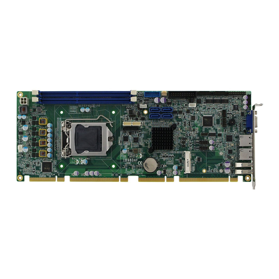
- Page 1 IB980 Intel 4th Generation Core / Q87 PCH ® PICMG 1.3 SHB Express Full-Size CPU Card USER’S MANUAL Version 1.1...
- Page 2 4th Generation Core DC/QC Processor are registered trademarks of Intel Corporation. Microsoft Windows is a registered trademark of Microsoft Corporation. Fintek is a registered trademark of Fintek Electronics Corporation. All other product names or trademarks are properties of their respective owners. IB980 User’s Manual...
-
Page 3: Table Of Contents
Board Dimensions ............... 7 Installations ............8 Installing the CPU ............... 9 Installing the Memory ............10 Setting the Jumpers ............11 Connectors on IB980 ............16 BIOS Setup ............29 Drivers Installation ........57 Intel Chipset Software Installation Utility ......58 VGA Drivers Installation .......... - Page 4 This page is intentionally blank. IB980 User’s Manual...
-
Page 5: Introduction
The IB980 PICMG1.3 board utilizes the dramatic increase in performance provided Intel’s latest cutting-edge technology. Measuring 338mm x122mm, the IB980 offers fast 6Gbps SATA support (6 ports), USB3.0 (4 ports) and interfaces for DVI-D, VGA and LVDS displays. IB980 FEATURES: •... -
Page 6: Checklist
INSTALLATIONS Checklist Your IB980 package should include the items listed below. • The IB980 PICMG1.3 SHB • This User’s Manual • 1 CD containing chipset drivers and flash memory utility • Serial ATA cable IB980 User’s Manual... -
Page 7: Ib980 Specifications
Mini PCIe socket x1@ component side [Full-sized] Expansion Slots Support USB client & mSATA [share with onboard SATA] Support PCIe signal Edge DB15 x1 for VGA Connector RJ45 x 2 for LAN 1 & 2 USB 3.0 x 2 IB980 User’s Manual... - Page 8 Operation Temperature: 0~60 degree C Storage Temperature: -20~80 degree C Relative humidity: 0~90%, non-condensing System +5V, +3.3V, +12V, -12V & 5VSB Voltage Operation Windows 7, Windows 8 System Certification CE /FCC/LVD RoHS Board Size 338mm x 126mm IB980 User’s Manual...
-
Page 9: Board Dimensions
INSTALLATIONS Board Dimensions IB980 User’s Manual... -
Page 10: Installations
INSTALLATIONS Installations This section provides information on how to use the jumpers and connectors on the IB980 in order to set up a workable system. The topics covered are: Installing the CPU .................. 9 Installing the Memory ................10 Setting the Jumpers ................11 Connectors on IB980 ................ -
Page 11: Installing The Cpu
INSTALLATIONS Installing the CPU The IB980 board supports an LGA1150 Socket (shown below) for Intel Sandy Bridge processors. To install the CPU, unlock first the socket by pressing the lever sideways, then lift it up to a 90-degree. Then, position the CPU above the socket such that the CPU corner aligns with the gold triangle matching the socket corner with a small triangle. -
Page 12: Installing The Memory
INSTALLATIONS Installing the Memory The IB980 board supports four DDR3 memory socket for a maximum total memory of 16GB in DDR3 DIMM memory type. Installing and Removing Memory Modules To install the DDR3 modules, locate the memory slot on the board and perform the following steps: 1. -
Page 13: Setting The Jumpers
INSTALLATIONS Setting the Jumpers Jumpers are used on IB980 to select various settings and features according to your needs and applications. Contact your supplier if you have doubts about the best configuration for your needs. The following lists the connectors on IB980 and their respective functions. -
Page 14: Jumper Locations On Ib980
INSTALLATIONS Jumper Locations on IB980 Jumpers on IB980 ................Page JBAT1: Clear CMOS Contents ............13 JP1: COM1 RS232 RI/+5V/+12V Power Setting ........ 13 JP7: Flash Descriptor Security Override (Factory use only) ....14 JP11 LVDS Panel Power Selection............14 JP14: BL_ADJ_LEVEL Setting ............ -
Page 15: Jbat1: Clear Cmos Contents
INSTALLATIONS JBAT1: Clear CMOS Contents JBAT1 Setting Function Pin 1-2 Normal Short/Closed Pin 2-3 Clear CMOS Short/Closed JP1: COM1 RS232 RI/+5V/+12V Power Setting Setting Function Pin 1-3 +12V Short/Closed Pin 3-4 Short/Closed Pin 5-3 Short/Closed IB980 User’s Manual... -
Page 16: Jp7: Flash Descriptor Security Override (Factory Use Only)
INSTALLATIONS JP7: Flash Descriptor Security Override (Factory use only) Flash Descriptor Security Override Disabled Open (Default) Close Enabled JP11: LVDS Panel Power Selection JP11 Setting Panel Voltage Pin 1-2 3.3V (default) Short/Closed Pin 2-3 Short/Closed IB980 User’s Manual... -
Page 17: Jp14: Bl_Adj_Level Setting
INSTALLATIONS JP14: BL_ADJ_LEVEL Setting JP14 Function Open 3.3V(default) Close JP13: BL Voltage TYPE Setting JP13 Setting Function Pin 1-2 DC Mode Short/Closed Pin 2-3 PWM Mode Short/Closed IB980 User’s Manual... -
Page 18: Connectors On Ib980
INSTALLATIONS Connectors on IB980 Connector Locations on IB980 ............17 J1: COM1 and COM2 Serial Ports ............18 J2: COM3 and COM4 Serial Ports ............18 CN3, CN4, CN5, CN6: SATA3 Connectors ........18 CN7: DB-15 VGA Connector .............. 19 J4: USB3.0/2.0 Connector .............. -
Page 19: Connector Locations On Ib980
INSTALLATIONS Connector Locations on IB980 IB980 User’s Manual... -
Page 20: J1: Com1 And Com2 Serial Ports
DCD2 RTS2 RXD2 CTS2 TXD2 DTR2 Ground J2: COM3, COM4 Serial Port [HRS_DF11-20DP-2DSA(08)] Signal Name Pin # Pin # Signal Name DSR3 DCD3 RTS3 RXD3 CTS3 TXD3 DTR3 Ground DSR4 DCD4 RTS4 RXD4 CTS4 TXD4 DTR4 Ground IB980 User’s Manual... -
Page 21: Cn3, Cn4, Cn5, Cn6: Sata3 Connectors
Pin # Signal Name Green Blue N.C. N.C. DDCDATA HSYNC VSYNC DDCCLK J4: USB3.0/2.0 Connector [PINREX_52X-40-20GU52] Signal Name Pin # Pin # Signal Name VCC(900mA) P1_SSRX- VCC(900mA) P1_SSRX+ P2_SSRX- P2_SSRX+ P1_SSTX- P1_SSTX+ P2_SSTX- P2_SSTX+ P1_U2_D- P1_U2_D+ P2_U2_D- P2_U2_D+ IB980 User’s Manual... -
Page 22: J15,J16: Usb2.0 Connector
VCC(500mA) VCC(500mA) Ground Ground CN8: Gigabit LAN (Intel I211AT) Connector CN9: Gigabit LAN (Intel I217LM) Connector J17: LCD Backlight Connector [E-CALL_0110-161-040] Pin # Signal Name Backlight Power +12V(2A) Backlight Enable Backlight Control Ground CN11, CN12: USB3.0 Connectors IB980 User’s Manual... -
Page 23: J3: Front Panel Function Connector
INSTALLATIONS J3: Front Panel Function Connector Signal Name Pin # Pin # Signal Name Speaker Out Ground Ground Ground Ground Ground PWR_SW Ground HDD LED + HDD LED - CN1,CN2: DDR3 DIMM Socket IB980 User’s Manual... -
Page 24: J6: External Audio Connector (Df11 Connector)
LINE OUT_L Ground JD_FRONT LINE IN_R LINE IN_L Ground JD_LINE IN MIC-R MIC-L Ground JD_MIC1 J7: ATX 12V Power Connector [Win Win_WPO-04D4TN431UW] This connector supplies the CPU operating voltage. Pin # Signal Name Ground Ground +12V-IN +12V-IN IB980 User’s Manual... -
Page 25: J12: Digital I/O 4 In/4 Out
Pin # Signal Name OUT3 OUT1 OUT2 OUT0 J9: PS/2 Keyboard and Mouse Connectors [HK_DF11-8S-PA66H] Signal Name Pin # Pin # Signal Name VCC(300mA) VCC(300mA) KB_DATA MS_DATA KB_CLK MS_CLK Ground Ground J10: SPI Flash Connector (Factory use only) IB980 User’s Manual... -
Page 26: J5: Parallel Port
PD4, parallel data 4 Ground PD5, parallel data 5 Ground PD6, parallel data 6 Ground PD7, parallel data 7 Ground ACK, acknowledge Ground Busy Ground Paper empty Ground Select Ground J8: MCU Flash Connector (factory use only) IB980 User’s Manual... -
Page 27: J13: Dvi-D Port (Df11 Connector)
CN10: Mini PCIE Connector (Support M-SATA with CN5) CN10 also supports mSATA. However, when CN10 is used for mSATA, then CN5 SATA port cannot be used. Only one of them can be used at one time to support SATA. IB980 User’s Manual... -
Page 28: Cpu_Fan1: Cpu Fan Power Connector
INSTALLATIONS CPU_FAN1: CPU Fan Power Connector Pin # Signal Name Ground +12V(1A) Rotation detection Control SYS_FAN1: System Fan1 Power Connector Pin # Signal Name Ground +12V(1A) Rotation detection IB980 User’s Manual... -
Page 29: J18,J19: Lvds Connectors
INSTALLATIONS J18, J19: LVDS Connectors [HIROSE_DF20G-20DP-1V(56)] Signal Name Pin # Pin # Signal Name LCD_PWR(1A) LCD_PWR(1A) LD3+ LD3- CLK+ CLK- LD2+ LD2- LD1+ LD1- LD0+ LD0- J18(Odd Bus), J19(Even Bus) IB980 User’s Manual... - Page 30 INSTALLATIONS This page is intentionally left blank. IB980 User’s Manual...
-
Page 31: Bios Setup
The topics covered in this chapter are as follows: BIOS Introduction ................30 BIOS Setup ..................30 Advanced Settings ................32 Chipset Settings ................... 45 Boot Settings..................53 CSM parameters .................. 54 Security Settings .................. 55 Save & Exit Settings ................56 IB980 User’s Manual... -
Page 32: Bios Introduction
These defaults have been carefully chosen by both AMI and your system manufacturer to provide the absolute maximum performance and reliability. Changing the defaults could cause the system to become unstable and crash in some cases. IB980 User’s Manual... - Page 33 F3: Optimized Default F4: Save ESC: Exit System Language Choose the system default language. System Date Set the Date. Use Tab to switch between Data elements. System Time Set the Time. Use Tab to switch between Data elements. IB980 User’s Manual...
-
Page 34: Advanced Settings
Enables or Disables 64bit capable devices to be decoded in above 4G address space (only if system supports 64 bit PCI decoding). PCI Latency Timer Value to be programmed into PCI Latency Timer Register. VGA Palette Snoop Enables or disables VGA Palette Registers Snooping. IB980 User’s Manual... - Page 35 If ENABLED allows device to use 8-bit Tag field as a requester. No Snoop Enables or disables PCI Express Device No Snoop option. Maximum Payload Set Maximum Payload of PCI Express Device or allow System BIOS to select the value. IB980 User’s Manual...
- Page 36 On non-PCI Express aware OS’s (Pre Windows Vista) some devices may not be correctly reinitialized after S3.Enabling this restors PCI Express device configuration on S3 resume Warning: Enabling this may cause issues with other hardware after S3 resume. IB980 User’s Manual...
- Page 37 This option may be not effective with some OS. ACPI Sleep State Select ACPI sleep state the system will enter, when the SUSPEND button is pressed. Lock Legacy Resources Enabled or Disabled Lock of Legacy Resources. S3 Video Repost Enable or disable S3 Video Repost. IB980 User’s Manual...
- Page 38 Enter: Select Intel Virtualization Technology Enabled Change Field Hardware Prefetcher Disabled F1: General Help Adjacent Cache Line Prefetch Enabled F2: Previous Values EIST Enabled F3: Optimized Default Turbo Mode Enabled F4: Save ESC: Exit Intel TXT(LT) Support Disabled IB980 User’s Manual...
- Page 39 Hardware Prefetcher To turn on/off the Mid level Cache (L2) streamer Prefetcher. Adjacent Cache Line Prefetch To turn on/off prefetching of adjacent cache lines. EIST Enabled/Disabled Intel Speedstep Intel TXT(LT) Support Enables or Disables Intel (R)TXT (LT) Support. IB980 User’s Manual...
- Page 40 F2: Previous Values Software Preserve Unknown F3: Optimized Default SATA Port5 Empty F4: Save ESC: Exit Software Preserve Unknown SATA Controller(s) Enable / Disable Serial ATA Controller. SATA Mode Selection (1) IDE Mode. (2) AHCI Mode. (3) RAID Mode. IB980 User’s Manual...
- Page 41 NXP3460 Configuration → ← Select Screen DP/eDP LVDS Control Disable ↑↓ Select Item Enter: Select Change Field F1: General Help F2: Previous Values F3: Optimized Default F4: Save ESC: Exit DP/eDP LVDS Control Enable / Disable DP(eDP) LVDS. IB980 User’s Manual...
- Page 42 Temperature Guardian Generate the reset signal when system hangs up on POST. ISmart Controller Setup the power on time for the system. Schedule Slot 1 / 2 Setup the hour/minute for system power on. IB980 User’s Manual...
- Page 43 Set timer to wait before sending ASF_GET_BOOT_OPTIONS. Activate Remote Assistance Process Trigger CIRA boot. PET Progress User can Enable/Disable PET Events progress to receive PET events or not. Watchdog Timer This configuration is supported only with IB980VF (with iAMT function). Enable/Disable Watchdog Timer. IB980 User’s Manual...
- Page 44 The EHCI ownership change should be claimed by EHCI driver. USB Mass Storage Driver Support Enable/Disable USB Mass Storage Driver Support. USB Transfer time-out The time-out value for Control, Bulk, and Interrupt transfers. Device reset tine-out USB mass Storage device start Unit command time-out. IB980 User’s Manual...
- Page 45 Select an optimal settings for the Super IO Device. Standby Power on S5 [ All Enable] Provide the Standby Power for devices.[All Disable] Shutdown the Standby power. Parallel Port Configuration Set parameters of Parallel port (LPT/LPTE) IB980 User’s Manual...
- Page 46 PC health status. Fan1/Fan2 Smart Fan Control This field enables or disables the smart fan feature. At a certain temperature, the fan starts turning. Once the temperature drops to a certain level, it stops turning again. IB980 User’s Manual...
-
Page 47: Chipset Settings
Boot Security Save & Exit ► PCH-IO Configuration → ← ► System Agent (SA) Configuration Select Screen ↑↓ Select Item Enter: Select Change Field F1: General Help F2: Previous Values F3: Optimized Default F4: Save ESC: Exit IB980 User’s Manual... - Page 48 Wake on LAN Enable or disable integrated LAN to wake the system. (The Wake On LAN cannot be disabled if ME is on at Sx state.) SLP_S4 Assertion Width Select a minimum assertion width of the SLP_S4# signal. IB980 User’s Manual...
- Page 49 Enable or disable PCI Express Clock Gating for each root port. DMI Link ASPM Control The control of Active State Power Management on both NB side and SB side of the DMI link. PCIe-USB Glitch W/A PCIe-USB Glitch W/A for bad USB device(s) connected behind PCIE/PEG port. IB980 User’s Manual...
- Page 50 ESC: Exit USB Precondition Precondition work on USB host controller and root ports for faster enumeration. xHCI Mode Mode of operation of xHCI controller. USB Ports Per-Port Disable Control Control each of the USB ports (0~13) disabling. IB980 User’s Manual...
- Page 51 Enabled Azalia will be unconditionally be enabled. Auto = Azalia will be enabled if present, disabled otherwise. Azalia Docking Support Enable or Disable Azalia Docking Support of Audio Controller. Azalia PME Enable or Disable power Management capability of Audio Controller. IB980 User’s Manual...
- Page 52 F3: Optimized Default ► Memory Configuration F4: Save ESC: Exit VT-d Check to enable VT-d function on MCH. Enable NB CRID Enable or disable NB CRID WorkAround. C-State Pre-Wake Controls C-State Pre-Wake feature for ARAT, in SSKPD[57]. IB980 User’s Manual...
- Page 53 Keep IGD enabled based on the setup options. DVMT Pre-Allocated Select DVMT 5.0 Pre-Allocated (Fixed) graphics memory size used by the internal graphics device. DVMT Total Gfx Mem Select DVMT 5.0 total graphics memory size used by the internal graphics device. IB980 User’s Manual...
- Page 54 ↑↓ Select Item Enter: Select CAS Latency (tCL) Change Field F1: General Help Minimum delay time F2: Previous Values CAS to RAS (tRCDmin) F3: Optimized Default Row Precharge (tRPmin) F4: Save ESC: Exit Active to Precharge (tRASmin) IB980 User’s Manual...
-
Page 55: Boot Settings
Enables/Disables Quiet Boot option. Fast Boot Enables/Disables boot with initialization of a minimal set of devices required to launch active boot option. Has no effect for BBS boot options. Boot Option Priorities Sets the system boot order. IB980 User’s Manual... -
Page 56: Csm Parameters
Controls the execution of UEFI and Legacy Storage OpROM. Launch Video OpROM policy Controls the execution of UEFI and Legacy Video OpROM. Other PCI device ROM priority For PCI devices other than Network, Mass storage or Video defines which OpROM to launch. IB980 User’s Manual... -
Page 57: Security Settings
Change Field Minimum length F1: General Help Maximum length F2: Previous Values F3: Optimized Default Administrator Password F4: Save ESC: Exit User Password Administrator Password Set Setup Administrator Password. User Password Set User Password. IB980 User’s Manual... -
Page 58: Save & Exit Settings
Discard Changes done so far to any of the setup options. Restore Defaults Restore/Load Defaults values for all the setup options. Save as User Defaults Save the changes done so far as User Defaults. Restore User Defaults Restore the User Defaults to all the setup options. IB980 User’s Manual... -
Page 59: Drivers Installation
LAN Drivers Installation ..............65 Intel® Management Engine Interface ..........68 Intel® USB 3.0 Drivers ............... 70 IMPORTANT NOTE: After installing your Windows operating system, you must install first the Intel Chipset Software Installation Utility before proceeding with the drivers installation. IB980 User’s Manual... -
Page 60: Intel Chipset Software Installation Utility
Plug & Play INF support for Intel chipset components. Follow the instructions below to complete the installation. 1. Insert the DVD that comes with the board. Click Intel and then Intel(R) 8 Series Chipset Drivers. 2. Click Intel(R) Chipset Software Installation Utility. IB980 User’s Manual... - Page 61 4. Click Yes to accept the software license agreement and proceed with the installation process. 5. On the Readme File Information screen, click Next to continue the installation. 6. The Setup process is now complete. Click Finish to restart the computer and for changes to take effect. IB980 User’s Manual...
-
Page 62: Vga Drivers Installation
VGA Drivers Installation 1. Insert the DVD that comes with the board. Click Intel and then Intel(R) 8 Series Chipset Drivers. 2. Click Intel(R) Core(TM) i3/i5/i7 Graphics Driver. 3. When the Welcome screen appears, click Next to continue. IB980 User’s Manual... - Page 63 DRIVERS INSTALLATION 4. Click Yes to to agree with the license agreement and continue the installation. 5. On the screen shown below, click Install to continue. IB980 User’s Manual...
- Page 64 DRIVER INSTALLATION 6. Setup complete. Click Finish to restart the computer and for changes to take effect. IB980 User’s Manual...
-
Page 65: Realtek Hd Audio Driver Installation
DRIVERS INSTALLATION Realtek HD Audio Driver Installation 1. Insert the DVD that comes with the board. Click Intel and then Intel(R) 8 Series Chipset Drivers. 2. Click Realtek High Definition Audio Driver. IB980 User’s Manual... - Page 66 DRIVER INSTALLATION 3. On the Welcome to the InstallShield Wizard screen, click Yes to proceed with and complete the installation process. 4. The InstallShield Wizard Complete. Click Finish to restart the computer and for changes to take effect. IB980 User’s Manual...
-
Page 67: Lan Drivers Installation
DRIVERS INSTALLATION LAN Drivers Installation 1. Insert the DVD that comes with the board. Click Intel and then Intel(R) 8 Series Chipset Drivers. 2. Click Intel(R) PRO LAN Network Driver. IB980 User’s Manual... - Page 68 DRIVER INSTALLATION 3. Click Install Drivers and Software. 4. When the Welcome screen appears, click Next. IB980 User’s Manual...
- Page 69 6. Click the checkbox for Drivers in the Setup Options screen to select it and click Next to continue. 7. The wizard is ready to begin installation. Click Install to begin the installation. 8. When InstallShield Wizard is complete, click Finish. IB980 User’s Manual...
-
Page 70: Intel® Management Engine Interface
Intel® Management Engine Interface Follow the steps below to install the Intel Management Engine. 1. Insert the DVD that comes with the board. Click Intel and then Intel(R) 8 Series Chipset Drivers and then Intel(R) AMT 9.0 Drivers. IB980 User’s Manual... - Page 71 Management Engine Components, click the checkbox for Install Intel® Control Center & click Next. 3. Click Yes to to agree with the license agreement. 4. When the Setup Progress screen appears, click Next. Then, click Finish when the setup progress has been successfully installed. IB980 User’s Manual...
-
Page 72: Intel® Usb 3.0 Drivers
DRIVER INSTALLATION Intel® USB 3.0 Drivers 1. Insert the DVD that comes with the board. Click Intel and then Intel(R) 8 Series Chipset Drivers. 2. Click Intel(R) USB 3.0 Drivers. IB980 User’s Manual... - Page 73 DRIVERS INSTALLATION 3. When the Welcome screen to the InstallShield Wizard for Intel® USB 3.0 eXtensible Host Controller Driver, click Next. 4. Click Yes to to agree with the license agreement and continue the installation. IB980 User’s Manual...
- Page 74 5. On the Readme File Information screen, click Next to continue the installation of the Intel® USB 3.0 eXtensible Host Controller Driver. 6. Setup complete. Click Finish to restart the computer and for changes to take effect. IB980 User’s Manual...
-
Page 75: Appendix
0F0h Clear Math Coprocessor Busy Signal 0F1h Reset Math Coprocessor 1F0h - 1F7h IDE Interface 2F8h - 2FFh Serial Port #2(COM2) 2B0h- 2DFh Graphics adapter Controller 360h - 36Fh Network Ports 3F8h - 3FFh Serial Port #1(COM1) IB980 User’s Manual... -
Page 76: Interrupt Request Lines (Irq)
The following table shows the IRQ used by the devices on board. Level Function IRQ0 System Timer Output IRQ1 Keyboard IRQ3 Serial Port #2 IRQ4 Serial Port #1 IRQ8 Real Time Clock IRQ14 Primary IDE IRQ15 Secondary IDE IB980 User’s Manual... -
Page 77: Watchdog Timer Configuration
Fintek 81846, program abort.\n"); return(1); }//if (SIO == 0) if (argc != 2) printf(" Parameter incorrect!!\n"); return (1); bTime = strtol (argv[1], endptr, 10); printf("System will reset after %d seconds\n", bTime); if (bTime) EnableWDT(bTime); } else DisableWDT(); return 0; IB980 User’s Manual... - Page 78 //--------------------------------------------------------------------------- void DisableWDT(void) unsigned char bBuf; Set_F81846_LD(0x07); //switch to logic device 7 bBuf = Get_F81846_Reg(0xFA); bBuf &= ~0x01; Set_F81846_Reg(0xFA, bBuf); //disable WDTO output bBuf = Get_F81846_Reg(0xF5); bBuf &= ~0x20; bBuf |= 0x40; Set_F81846_Reg(0xF5, bBuf); //disable WDT //--------------------------------------------------------------------------- IB980 User’s Manual...
- Page 79 F81846_UNLOCK); outportb(F81846_INDEX_PORT, F81846_UNLOCK); //--------------------------------------------------------------------------- void Lock_F81846 (void) outportb(F81846_INDEX_PORT, F81846_LOCK); //--------------------------------------------------------------------------- void Set_F81846_LD( unsigned char LD) Unlock_F81846(); outportb(F81846_INDEX_PORT, F81846_REG_LD); outportb(F81846_DATA_PORT, LD); Lock_F81846(); //--------------------------------------------------------------------------- void Set_F81846_Reg( unsigned char REG, unsigned char DATA) Unlock_F81846(); outportb(F81846_INDEX_PORT, REG); outportb(F81846_DATA_PORT, DATA); Lock_F81846(); //--------------------------------------------------------------------------- IB980 User’s Manual...
- Page 80 (F81846_BASE) #define F81846_DATA_PORT (F81846_BASE+1) //--------------------------------------------------------------------------- #define F81846_REG_LD 0x07 //--------------------------------------------------------------------------- #define F81846_UNLOCK 0x87 #define F81846_LOCK 0xAA //--------------------------------------------------------------------------- unsigned int Init_F81846(void); void Set_F81846_LD( unsigned char); void Set_F81846_Reg( unsigned char, unsigned char); unsigned char Get_F81846_Reg( unsigned char); //--------------------------------------------------------------------------- #endif //__F81846_H IB980 User’s Manual...
Need help?
Do you have a question about the IB980 and is the answer not in the manual?
Questions and answers