Table of Contents
Advertisement
Quick Links
Advertisement
Table of Contents

Related Manuals for IBASE Technology IP414


Summary of Contents for IBASE Technology IP414
- Page 1 IP414 ATX COM Express Type 6 Baseboard User’s Manual Version 1.0 (July 2023)
- Page 2 IBASE Technology, Inc. (hereinafter referred to as “IBASE”). Disclaimer IBASE reserves the right to make changes and improvements to the products described in this document without prior notice.
- Page 3 0.1% by weight (1000 ppm) except for cadmium, limited to 0.01% by weight (100 ppm). • Lead (Pb) • Mercury (Hg) • Cadmium (Cd) • Hexavalent chromium (Cr6+) • Polybrominated biphenyls (PBB) • Polybrominated diphenyl ether (PBDE) IP414 User’s Manual...
- Page 4 Danger of explosion if the internal lithium-ion battery is replaced by an incorrect type. Replace only with the same or equivalent type recommended by the manufacturer. Dispose of used batteries according to the manufacturer’s instructions or recycle them at a local recycling facility or battery collection point. IP414 User’s Manual...
- Page 5 Software in use (such as OS and application software, including the version numbers) If repair service is required, you can download the RMA form at http://www.ibase.com.tw/english/Supports/RMAService/. Fill out the form and contact your distributor or sales representative. IP414 User’s Manual...
-
Page 6: Table Of Contents
Board View ..................5 Dimensions ..................7 Chapter 2 Hardware Configuration .......... 8 Setting the Jumpers ................9 Connector Locations on IP414 ............10 Jumpers Quick Reference ..............11 2.3.1 LVDS Panel Power (JP1) ............ 11 2.3.2 eDP / LVDS Selection (JP2) ..........12 2.3.3... - Page 7 2.4.20 ATX Power Connector (J23) ..........37 2.4.21 ATX 12V Power Connector (J24).......... 38 2.4.23 PCIe (x4) Slot (PCIE1, PCIE2) ..........39 2.4.24 PCIe (x16) Slot (PCIEX16) ........... 40 PCIe (x1) Slot (PCIE3, PCIE4) ..........41 2.4.25 IP414 User’s Manual...
- Page 8 This page is intentionally left blank. IP414 User’s Manual viii...
-
Page 9: Chapter 1 General Information
Chapter 1 General Information The information provided in this chapter includes: • Features • Specifications • Board View • Board Dimensions... -
Page 10: Introduction
Introduction IP414 / IP414-DC is a carrier board with ATX form factor for COM Express Type 6 CPU module; it is compatible with the ET980 COMe module and features expansion slots including PCIe (x1), PCIe (x4) PCIe (x16) and M.2 E-Key / B-Key / M-Key and video outputs (eDP / LVDS, DP++, VGA). -
Page 11: Specifications
General Information Specifications • IP414 (supports ATX Power) Models • IP414-DC (supports DC-In) Form Factor ATX COM Express Type 6 baseboard 305 x 244 mm (12” x 9.61”) Dimensions RoHS I/O Ports / Connectors • ATX Power • DC-In (If your CPU module supports 12V only,... - Page 12 2 x PCIe (x4) slot Slots • 2 x PCIe (x1) slot Environment Operation: 0 ~ 60 °C • Temperature Storage: -20 ~ 80 °C • Relative 10 ~ 90 % Humidity All specifications are subject to change without prior notice. IP414 User’s Manual...
-
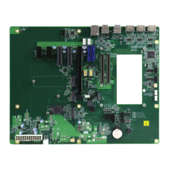
Page 13: Board View
General Information Board View Top View IP414 IP414-DC IP414 User’s Manual... - Page 14 *Warning: The DC-in power connector can be used only with COM Express Modules that supports modules 8V~20V power. If your CPU module supports 12V only, please use a 12V power adaptor to avoid malfunction or any damage to your equipment (e.g., ET980). IP414 User’s Manual...
-
Page 15: Dimensions
General Information Dimensions IP414 User’s Manual... -
Page 16: Chapter 2 Hardware Configuration
Chapter 2 Hardware Configuration This section provides information on jumper settings and connectors on the IP414 in order to set up a workable system. • Jumper and connector locations • Jumper settings and information of connectors... -
Page 17: Setting The Jumpers
Hardware Configuration Setting the Jumpers Set up and configure your IP414 by using jumpers for various settings and features according to your needs and applications. Contact your supplier if you have doubts about the best configuration for your use. 2.2.1... -
Page 18: Connector Locations On Ip414
Connector Locations on IP414 IP414 User’s Manual... -
Page 19: Jumpers Quick Reference
Hardware Configuration Jumpers Quick Reference Function Jumper Page LVDS Panel Power eDP / LVDS Selection eDP Panel Brightness Selection LVDS Backlight Power Selection eDP Panel Power 2.3.1 LVDS Panel Power (JP1) Function Pin closed Illustration 3.3V (default) IP414 User’s Manual... -
Page 20: Edp / Lvds Selection (Jp2)
2.3.2 eDP / LVDS Selection (JP2) Function Pin closed Illustration (default) LVDS IP414 User’s Manual... -
Page 21: Edp Panel Brightness Selection (Jp3)
Hardware Configuration 2.3.3 eDP Panel Brightness Selection (JP3) Function Pin closed Illustration (default) IP414 User’s Manual... -
Page 22: Lvds Backlight Power Selection (Jp4)
2.3.4 LVDS Backlight Power Selection (JP4) Function Pin closed Illustration 3.3V (default) IP414 User’s Manual... -
Page 23: Edp Panel Power (Jp5)
Hardware Configuration 2.3.5 eDP Panel Power (JP5) Function Pin closed Illustration 3.3V (default) IP414 User’s Manual... -
Page 24: Connectors Quick Reference
(x1), USB 2.0, USB 3.0 SIM Card System Function Connector Digital I/O Connector COM3 & COM4 RX/TX Port J19, J20 ATX Power Connector ATX 12V Power Connector PCIe (x4) Slot PCIE1, PCIE2 PCIe (x16) Slot PCIEX16 PCIe (x1) Slot PCIE3, PCIE4 IP414 User’s Manual... -
Page 25: Usb 3.0 Connector (Cn1, Cn5)
Hardware Configuration 2.4.1 USB 3.0 Connector (CN1, CN5) Note: CN1 only.1 Port USB 3.0 Assignment Assignment SSRX- Data- SSRX+ Data+ Ground Ground SSTX- SSTX+ IP414 User’s Manual... -
Page 26: Displayport (Cn2, Cn3, Cn4)
2.4.2 DisplayPort (CN2, CN3, CN4) Assignment Assignment LAN0_P LAN3_N LAN0_N CONFIG LAN1_P AUXP LAN1_N LAN2_P AUXN Hot Plug LAN2_N LAN3_P IP414 User’s Manual... -
Page 27: G Gigabit Lan (Cn6)
Hardware Configuration 2.4.3 2.5G Gigabit LAN (CN6) Assignment MDI0+ MDI0- MDI1+ MDI2+ MDI2- MDI1- MDI3+ IP414 User’s Manual... -
Page 28: Sata Connectors (Cn7, Cn8, Cn9, Cn10)
2.4.4 SATA Connectors (CN7, CN8, CN9, CN10) Note: ET980 only.FOR CN7,CN9 Assignment Assignment Ground Ground Ground IP414 User’s Manual... -
Page 29: Lvds Connector (Cn11, Cn12)
Hardware Configuration 2.4.5 LVDS Connector (CN11, CN12) Note: CN11 (Channel2), CN12 (Channel1) Signal Name Signal Name TX0P TX0N Ground Ground TX1P TX1N Ground Ground TX2P TX2N Ground Ground CLKP CLKN Ground Ground TX3P TX3N Power Power IP414 User’s Manual... -
Page 30: Edp Connector (Cn13)
2.4.6 eDP Connector (CN13) Signal Name Signal Name Ground BL_Power BL_Power Panel_VDD BL_Power Panel_VDD BL_Power Ground AUX_N AUX_P Brightness Ground Bklt_en TX0_P Ground TX0_N Ground Ground Ground TX1_P Ground TX1_N Ground Ground IP414 User’s Manual... -
Page 31: Dc-In Power Din 4P 8V~20V Input (Cn14)
Hardware Configuration 2.4.7 DC-In Power DIN 4P 8V~20V Input (CN14) Note: DC-in Power Connector (J25 or CN14) is available for IP414-DC only. *Warning: The DC-in connector can be used only with COM Express Modules that supports modules 8V~20V power. If your CPU module supports 12V only, please use a 12V power adaptor to avoid malfunction or any damage to your equipment. -
Page 32: Fan Power Connector (Cpu_Fan1, Sys_Fan1)
2.4.8 Fan Power Connector (CPU_FAN1, SYS_FAN1) Assigment Assigment Ground +12V IP414 User’s Manual... -
Page 33: Vga Port (Vga1)
Hardware Configuration 2.4.9 VGA Port (VGA1) Signal Name Signal Name CRT1_RED CRT1_GREEN Ground CRT1_BLUE CRT1_DDC_DATA_ISO Ground CRT1_HSYN_R Ground CRT1_VSYN_R Ground CRT1_DDC_CLK_ISO Ground IP414 User’s Manual... -
Page 34: Sata Power Connector (J2, J3)
2.4.10 SATA Power Connector (J2, J3) Signal Name Signal Name Ground Ground +12V IP414 User’s Manual... -
Page 35: Com1 & Com2 Rs-232 Ports (J6, J5)
Hardware Configuration 2.4.11 COM1 & COM2 RS-232 Ports (J6, J5) Signal Name Signal Name Data carrier detect Receive data Transmit data Data terminal ready Ground Data set ready Request to send Clear to send Ring indicator IP414 User’s Manual... -
Page 36: M-Key 2280 (J7)
2.4.12 M.2 M-Key 2280 (J7) Note: M.2 M-Key (J7) is available for ET980 only. Assignment Assignment +3.3V +3.3V PERn3 PERp3 HDD_LED# PETn3 +3.3V PETp3 +3.3V +3.3V PERn2 +3.3V PERp2 PETn2 PETp2 PERn1 PERp1 PETn1 PETp1 IP414 User’s Manual... - Page 37 Hardware Configuration PERn0 PERp0 PETn0 PETp0 PERST# CLKREQ# REFCLKn PEWAKE# REFCLKp M-KEY M-KEY SUSCLK +3.3V +3.3V +3.3V IP414 User’s Manual...
-
Page 38: Usb 2.0 Connector (J9)
2.4.13 USB 2.0 Connector (J9) Signal Name Signal Name Ground Ground IP414 User’s Manual... -
Page 39: E-Key (2230) Connector Pcie (X1), Usb 2.0 (J10)
Hardware Configuration 2.4.14 M.2 E-Key (2230) Connector PCIe (x1), USB 2.0 (J10) IP414 User’s Manual... -
Page 40: Panel Inverter Power Connector (J11)
2.4.15 Panel Inverter Power Connector (J11) Signal Name Signal Name +12V Backlight Enable Ground IP414 User’s Manual... -
Page 41: B-Key (3052) Connector Pcie (X1), Usb 2.0, Usb 3.0 Sim Card (J16)
Hardware Configuration 2.4.16 M.2 B-Key (3052) Connector PCIe (x1), USB 2.0, USB 3.0 SIM Card (J16) IP414 User’s Manual... -
Page 42: System Function Connector ( J17)
The reset switch allows you to reset the system without turning the main power switch off and then on again. • Power LED (Pins 7 and 8) This connector connects to the system power LED on control panel. This LED will light when the system turns on. IP414 User’s Manual... -
Page 43: Digital I/O Connector (J18)
Hardware Configuration 2.4.18 Digital I/O Connector (J18) Signal Name Signal Name Gorund OUT3 OUT1 OUT2 OUT0 IP414 User’s Manual... -
Page 44: Com3 & Com4 Rx/Tx Port (J19, J20)
2.4.19 COM3 & COM4 RX/TX Port (J19, J20) Note: J20 (COM4), J19 (COM3) Signal Name Signal Name RXD, Receive data TXD, Transmit data Ground IP414 User’s Manual... -
Page 45: Atx Power Connector (J23)
Hardware Configuration 2.4.20 ATX Power Connector (J23) Note: ATX Power Connector (J23, J24) is available for IP414 only. Signal Name Signal Name 3.3V 3.3V 3.3V -12V Ground Ground PS-ON Ground Ground Ground Ground Ground Power good 5VSB +12V +12V +3.3V Ground IP414 User’s Manual... -
Page 46: Atx 12V Power Connector (J24)
2.4.21 ATX 12V Power Connector (J24) Signal Name Signal Name Ground Ground +12V +12V IP414 User’s Manual... -
Page 47: Pcie (X4) Slot (Pcie1, Pcie2)
Hardware Configuration 2.4.22 PCIe (x4) Slot (PCIE1, PCIE2) Note: Available for ET980 only IP414 User’s Manual... -
Page 48: Pcie (X16) Slot (Pciex16)
2.4.23 PCIe (x16) Slot (PCIEX16) Note: Not supported by ET980 IP414 User’s Manual... -
Page 49: Pcie (X1) Slot (Pcie3, Pcie4)
Hardware Configuration 2.4.24 PCIe (x1) Slot (PCIE3, PCIE4) IP414 User’s Manual...
Need help?
Do you have a question about the IP414 and is the answer not in the manual?
Questions and answers