Table of Contents
Advertisement
Quick Links
Advertisement
Table of Contents

Related Manuals for IBASE Technology AMS100-807-PCI


Summary of Contents for IBASE Technology AMS100-807-PCI
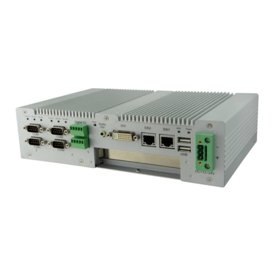
- Page 1 AMS100-807 Series Fanless System Users Manual Version 1.0...
-
Page 2: Table Of Contents
Table of Contents Chapter 1 Specifications ........................3 Chapter 2 AMS100-807 Series Features..................4 Chapter 3 System Dimensions ......................5 Chapter 4 Opening the Chassis ....................... 6 Chapter 5 Installing the Memory Module ..................6 Installing the 2.5” HDD..................... 7 Chapter 6 Chapter 7 Installing the Mini PCI-e Module .................. - Page 3 Safety Information AMS100-807 is designed and tested to meet the latest standards of safety for information technology equipment. However, to ensure your safety, it is important that you read the following safety instructions. Setting up your system • Read and follow all instructions in the documentation before you operate your system. •...
-
Page 4: Specifications
Chapter 1 Specifications Form Factor Fanless system Intel “Cedar view” Processor, 32nm Bulk CPU Type Atom D2550 = 1.86 GHz [TDP= 10W] Operating Frequency Cores = Dual Core Chipset Intel “Tiger Point” PCH, CG82NM10 [TDP = 2.1W, 130 nm] BIOS AMI BIOS w/ACPI CPU on-die memory controller supporting up to 4GB Memory... -
Page 5: Ams100-807 Series Features
Non-operating: 1.0 grms / 5~500 Hz random operation Anti-vibration Operating: 0.25 grms / 5~500 Hz random operation Certifications CE, FCC, UL, CCC Support IBASE iSMART for auto-scheduler and power resume Features EuP/ErP compliant Switch RS-232 / 422 / 485 mode in BIOS (COM1 & COM2) Chapter 2 AMS100-807 Series Features ... -
Page 6: System Dimensions
Chapter 3 System Dimensions Unit: mm AMS100-807 Series User’s Manual... -
Page 7: Opening The Chassis
Chapter 4 Opening the Chassis Fig. 4-1 Loosen three #6-32 screws on front panel. Fig. 4-2 Loosen Four M3 screws on rear & top panel. Top screw is shorter. Fig. 4-3 The system Chapter 5 Installing the Memory Module Fig. 5-1 Insert DDR3 SO-DIMM memory module. AMS100-807 Series User’s Manual... -
Page 8: Installing The 2.5" Hdd
Chapter 6 Installing the 2.5” HDD Fig. 6-1 Loosen four screws to remove HDD Fig. 6-2 Insert the SATA cable bracket. Fig. 6-3 Put HDD on the bracket Fig. 6-4 Assemble cable and HDD shoulder screw Fig. 6-5 Fasten HDD on bracket with four shoulder screws. AMS100-807 Series User’s Manual... -
Page 9: Installing The Mini Pci-E Module
Fig. 6-6 Fasten HDD bracket with four screws. Chapter 7 Installing the Mini PCI-e Module Fig. 7-1 Insert Mini PCI-E module and fixed with two M2 screws. Chapter 8 Terminal Block (TB) DC Input Cathode Anode Ground Fig. 8-1 Screw tight the DC cables. Fig. -
Page 10: Rear Usb Cable
Chapter 9 Rear USB Cable Fig. 9-1 Plug USB cable onto the motherboard. Chapter 10 Rear COM 5 & COM6 Cable (Optional) COM 5 & 6 cable Fig. 10-1 Knock off two DB-9 opening and screw Fig. 10-2 Plug COM 5 & COM 6 cable onto the RS-232 connectors on chassis. -
Page 11: Installing The Add-On Card
Chapter 11 Installing the Add-on Card IP807 --- PCI Riser Card IP808 --- PCI-E Riser Card Fig. 11-1 Make sure the add-on card interface. Fig. 11-2 Loosen slot screw. Fig. 11-3 Remove HDD kit. Fig. 11-4 Insert add-on card and fasten the screw. Fig. -
Page 12: Assembling Mounting Brackets
Chapter 12 Assembling Mounting Brackets Fig. 12-1 Put mounting brackets on bottom and fasten with four screws. Chapter 13 Optional COM7 & COM8 Assembly Fig. 13-1 IBD-182V, IBASE RS-232 Mini PCI-E card Fig. 13-2 Insert IBD-182V and fixed with two M2 screws. Fig.
Need help?
Do you have a question about the AMS100-807-PCI and is the answer not in the manual?
Questions and answers