
Related Manuals for IBASE Technology IB936


Summary of Contents for IBASE Technology IB936
- Page 1 IB936 ® Socket LGA775 Pentium ® Intel Q35 Chipset PICMG 1.3 SHB Express CPU Card USER’S MANUAL Version 1.0...
- Page 2 Intel and Core 2 Duo, Core 2 Quad, and Celeron are registered trademarks of Intel Corporation. Microsoft Windows is a registered trademark of Microsoft Corporation. Winbond is a registered trademark of Winbond Electronics Corporation. All other product names or trademarks are properties of their respective owners. IB936 User’s Manual...
-
Page 3: Table Of Contents
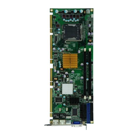
Specifications ..............3 Board Dimensions ............... 4 Installations ............5 Installing the CPU ............... 6 Installing the Memory ............7 Setting the Jumpers ............. 8 Connectors on IB936 ............12 BIOS Setup ............23 Drivers Installation ........45 Appendix ............53 A. - Page 4 The IB936F CPU Card IB936 User’s Manual...
-
Page 5: Introduction
INTRODUCTION Introduction Product Description The IB936 PICMG1.3 SHB board incorporates the Intel® Q35 Express Chipset, consisting of the Intel® Q35 Graphic Memory Controller Hub (GMCH) and Intel® I/O Controller Hub 9 (ICH9), is an optimized integrated graphics solution with a 800/1066/1333 MHz front-side bus. -
Page 6: Checklist
Checklist ® Your IB936 Pentium 4 CPU card package should include the items listed below: The IB936 CPU card This User’s manual 1 Floppy cable 1 IDE cable 1 USB cable with bracket (USB2K-4) 1 Y-Cable supporting a PS/2 Keyboard and a PS/2 Mouse ... -
Page 7: Specifications
+5V, +3.3V, +12V, 5VSB (2A) Modem Wakeup, LAN Wakeup Other 338mm x 126mm Board Size PCI w/ 4x PCI master (Supports 4 PCI Slots) Golden Finger I/F 4x (x1 PCIe slots) (Also Backplane Spec.) 1x (x16 PCIe slot) 4x USB2.0 ports IB936 User’s Manual... -
Page 8: Board Dimensions
INTRODUCTION Board Dimensions IB936 User’s Manual... -
Page 9: Installations
INSTALLATIONS Installations This section provides information on how to use the jumpers and connectors on the IB936 in order to set up a workable system. The topics covered are: Installing the CPU .................. 6 Installing the Memory ................7 Setting the Jumpers ................8 Connectors on IB936 ................ -
Page 10: Installing The Cpu
INSTALLATIONS Installing the CPU The IB936 board supports an LGA 775 processor socket for Intel Core 2 Duo and Intel Core2 Quad processors, and Intel Celeron 400(Conroe-L) Sequence processor. The LGA 775 processor socket comes with a lever to secure the processor. -
Page 11: Installing The Memory
INSTALLATIONS Installing the Memory The IB936 board supports two DDR2 memory sockets for a maximum total memory of 4GB in DDR2 memory type. It supports DDR2 667/800. Basically, the system memory interface has the following features: Supports two 64-bit wide DDR data channels Available bandwidth up to 6.4GB/s (DDR2 800) for single-channel... -
Page 12: Setting The Jumpers
INSTALLATIONS Setting the Jumpers Jumpers are used on IB936 to select various settings and features according to your needs and applications. Contact your supplier if you have doubts about the best configuration for your needs. The following lists the connectors on IB936 and their respective functions. -
Page 13: Jumper Locations On Ib936
INSTALLATIONS Jumper Locations on IB936 Jumpers on IB936 ................Page JP1, JP2, JP3: RS232/422/485 (COM2) Selection ......10 JP4: Configure and Recovery (Factory use only) ........ 10 JP5: Power ON Setting ................ 10 JP7: ICH9 PCI-E port 1-4 Configuration Settings ....... 11 JP11: Clear CMOS Contents ............... -
Page 14: Jp1, Jp2, Jp3: Rs232/422/485 (Com2) Selection
Setting Function Pin 1-2 Normal (default) Short/Closed Pin 2-3 Configure Short/Closed Recovery Open JP5: Power ON Setting Setting Function Pin 1-2 Power on by system Short/Closed button Pin 2-3 Power on by power Short/Closed supply AC on IB936 User’s Manual... -
Page 15: Jp7: Ich9 Pci-E Port 1-4 Configuration Settings
JP11: Clear CMOS Contents Use JP11 to clear the CMOS contents. Note that the ATX-power connector should be disconnected from the board before clearing CMOS. JP11 Setting Function Pin 1-2 Normal Short/Closed Pin 2-3 Clear CMOS Short/Closed IB936 User’s Manual... -
Page 16: Connectors On Ib936
INSTALLATIONS Connectors on IB936 The connectors on IB936 allow you to connect external devices such as keyboard, mouse, hard disk drives, printers… etc. The following table lists the connectors on IB936 and their respective functions. Connector Locations on IB936 ............13 ATX1: ATX 12V Power Connector ........... -
Page 17: Connector Locations On Ib936
INSTALLATIONS Connector Locations on IB936 IB936 User’s Manual... -
Page 18: Atx1: Atx 12V Power Connector
Pin # Signal Name Ground +12V Rotation detection Control SYS_FAN1, SYS_FAN2: System Fan Power Connector Pin # Signal Name Ground +12V Rotation detection CN1, CN2, CN3, CN4: SATA HDD Connector Pin # Signal Name Ground Ground Ground IB936 User’s Manual... -
Page 19: Ide1: Primary Ide Connector
Drive select 1 Ground Drive select 0 Ground Motor enable 1 Ground Direction Ground Step Ground Write data Ground Write gate Ground Track 00 Ground Write protect FDD1 Ground Read data Ground Side 1 select Ground Diskette change IB936 User’s Manual... -
Page 20: Vga1: Vga Crt Connector
PD2, parallel data 2 Select PD3, parallel data 3 Ground PD4, parallel data 4 Ground PD5, parallel data 5 Ground PD6, parallel data 6 Ground PD7, parallel data 7 Ground ACK, acknowledge Ground Busy Ground Paper empty Ground Select IB936 User’s Manual... -
Page 21: J3: Digital I/O Connector (4 In, 4 Out)
Signal Name Ground Out3 Out1 Out2 Out0 J4: IrDA Connector Pin # Signal Name No connect Ir RX Ground Ir TX J5: CD-In Audio Connector Pin # Signal Name CD Audio R Ground Ground CD Audio L IB936 User’s Manual... -
Page 22: J6: Com2 Serial Port
J7 is a 10-pin header support RS232 COM ports. Signal Signal Name Name J8: System Function Connector J8 provides connectors for system indicators that provide light indication of the computer activities and switches to change the computer status. IB936 User’s Manual... - Page 23 Reset Switch: Pins 9 and 19 The reset switch allows the user to reset the system without turning the main power switch off and then on again. Orientation is not required when making a connection to this header. IB936 User’s Manual...
-
Page 24: J9: Ps/2 Keyboard And Mouse Connector
J12 is a 3-pin header for the Wake On LAN function on the board. The following table shows the pin out assignments of this connector. Wake On LAN will function properly only with an ATX power supply with 5VSB that has 1A. Pin # Signal Name +5VSB Ground LAN Wakeup IB936 User’s Manual... -
Page 25: J13: Usb Connector
The following table shows the pin outs of the USB pin header. Signal Name Signal Name Ground USB2- USB3+ USB2+ USB3- Ground J15, J17: Gigabit LAN RJ45 Connector J15, J17 are Gigabit LAN RJ45 connectors. J16: SPI Debug Tools Port (Factory use only) IB936 User’s Manual... - Page 26 INSTALLATIONS This page is intentionally left blank. IB936 User’s Manual...
-
Page 27: Bios Setup
PNP/PCI Configurations ..............41 PC Health Status .................. 42 Frequency/Voltage Control ..............43 Load Fail-Safe Defaults ............... 44 Load Optimized Defaults ..............44 Set Supervisor Password ..............44 Save & Exit Setup ................44 Exit Without Saving................44 IB936 User’s Manual... -
Page 28: Bios Introduction
<PgUp> and <PgDn> keys to change entries, <F1> for help and <Esc> to quit. When you enter the Setup utility, the Main Menu screen will appear on the screen. The Main Menu allows you to select from various setup functions and exit choices. IB936 User’s Manual... - Page 29 These defaults have been carefully chosen by both Award and your system manufacturer to provide the absolute maximum performance and reliability. Changing the defaults could cause the system to become unstable and crash in some cases. IB936 User’s Manual...
-
Page 30: Standard Cmos Setup
Sun to Sat Month : 1 to 12 Date : 1 to 31 Year : 1999 to 2099 To set the date, highlight the “Date” field and use the PageUp/ PageDown or +/- keys to set the current time. IB936 User’s Manual... - Page 31 These fields identify the types of floppy disk drive A or drive B that has been installed in the computer. The available specifications are: 360KB 1.2MB 720KB 1.44MB 2.88MB 5.25 in. 5.25 in. 3.5 in. 3.5 in. 3.5 in. IB936 User’s Manual...
- Page 32 The system boot will not be halted for a disk error; it will stop for all other errors. All, But Disk/Key The system boot will not be halted for a key- board or disk error; it will stop for all others. IB936 User’s Manual...
-
Page 33: Advanced Bios Features
CPU. By default, these items are enabled. Quick Power On Self Test When enabled, this field speeds up the Power On Self Test (POST) after the system is turned on. If it is set to Enabled, BIOS will skip some items. IB936 User’s Manual... - Page 34 Settings are from 6 to 30 characters per second. Typematic Delay (Msec) When the typematic rate is enabled, this item allows you to set the time interval for displaying the first and second characters. By default, this item is set to 250msec. IB936 User’s Manual...
- Page 35 If you set this feature to Disabled, the BIOS will not report the missing floppy drive to Win95/98. Small Logo (EPA) Show The EPA logo appears at the right side of the monitor screen when the system is boot up. The default setting is Disabled. IB936 User’s Manual...
-
Page 36: Advanced Chipset Features
SDRAM is written to, read from or refreshed. Reducing the delay improves the performance of the SDRAM. DRAM RAS# Precharge This option sets the number of cycles required for the RAS to accumulate its charge before the SDRAM refreshes. IB936 User’s Manual... - Page 37 LVDS+TV or LVDS or TV-out setting, install the IBP190 module. SDVO LVDS Protocol: 1Ch 18bit SDVO Panel Number: 852 x 480 Boot Display: Auto Panel Scaling: Auto Panel Number: 1024 x 768 18bit SC Onboard LAN Boot ROM: Enabled Onboard IT8211F IDE ROM: Enabled IB936 User’s Manual...
- Page 38 UART Mode Select Normal RxD, TxD Active Hi, Lo IR Transmission Delay Enabled UR2 Duplex Mode Half Use IR Pins IR-Rx2Tx2 Onboard Parallel Port 378/IRQ7 Parallel Port Mode EPP Mode Select EPP1.7 ECP Mode Use DMA PWRON After PWR-Fail IB936 User’s Manual...
- Page 39 Select [AHCI] for Advanced Host Controller Interface (AHCI) feature, with improved SATA performance with native command queuing & native hot plug. Select [RAID] to use SATA as RAID function. RAID function is supported on the board if it uses ICH9R, but this is optional. IB936 User’s Manual...
- Page 40 The default values for these ports are: Serial Port 1 3F8/IRQ4 Serial Port 2 2F8/IRQ3 Parallel Port 378H/IRQ7 UART Mode Select This field determines the UART 2 mode in your computer. The default value is Normal. IB936 User’s Manual...
- Page 41 The options for this field are Enabled and Disabled. By default, this field is set to Disabled. USB Storage Function The options for this field are Enabled and Disabled. By default, this field is set to Disabled. IB936 User’s Manual...
-
Page 42: Power Management Setup
Min. Power Saving Minimum power management Max. Power Saving Maximum power management. User Define Each of the ranges is from 1 min. to 1hr. Except for HDD Power Down which ranges from 1 min. to 15 min. IB936 User’s Manual... - Page 43 When the system enters Doze mode, the CPU clock runs only part of the time. You may select the percent of time that the clock runs. Wake up by PCI Card By default, this field is disabled. IB936 User’s Manual...
- Page 44 When an I/O device wants to gain the attention of the operating system, it signals this by causing an IRQ to occur. When the operating system is ready to respond to the request, it interrupts itself and performs the service. IB936 User’s Manual...
-
Page 45: Pnp/Pci Configurations
PCI/VGA. When this field is enabled, a PCI/VGA can work with an MPEG ISA/VESA VGA card. When this field is disabled, a PCI/VGA cannot work with an MPEG ISA/VESA card. Maximum Payload Size The default setting of the PCI Express Maximum Payload Size is 128. IB936 User’s Manual... -
Page 46: Pc Health Status
PC health status. Smart Fan Temperature This field enables or disables the smart fan feature. At a certain temperature, the fan starts turning. Once the temperature drops to a certain level, it stops turning again. IB936 User’s Manual... -
Page 47: Frequency/Voltage Control
Auto Detect PCI Clk This field enables or disables the auto detection of the PCI clock. Spread Spectrum This field sets the value of the spread spectrum. The default setting is Disabled. This field is for CE testing use only IB936 User’s Manual... -
Page 48: Load Fail-Safe Defaults
Select this option to exit the Setup utility without saving the changes you have made in this session. Typing “Y” will quit the Setup utility without saving the modifications. Typing “N” will return you to Setup utility. IB936 User’s Manual... -
Page 49: Drivers Installation
F6 and follow the proceeding instructions. The IDE device drivers can be found in the driver DVD disc that is provided with the board with location in E:\SCSI\ITE8211\DISK\ (assuming E: is the DVD ROM drive). IB936 User’s Manual... - Page 50 Installation Utility, please update your system to Windows 2000 SP4 or Windows XP SP1A) 1. Insert the CD that comes with the board. Click Intel and then Intel(R) Q35 Chipset Drivers. 2. Click Intel(R) Chipset Software Installation Utility. IB936 User’s Manual...
- Page 51 5. On the Readme Information screen, click Next to continue the installation. 6. When the Setup Progress screen appears, click Next to continue. 7. The Setup process is now complete. Click Finish then restart the computer and for changes to take effect. IB936 User’s Manual...
- Page 52 5. On Readme File Information screen, click Next to continue. 6. On Setup Progress screen, click Next to continue the installation. 7. The Setup process is now complete. Click Finish to restart the computer and for changes to take effect. IB936 User’s Manual...
- Page 53 Q35 Chipset Drivers. 2. Click Realtek High Definition Codec Audio Driver. 3. When the Welcome screen appears, click Next to continue. 4. The Setup process is now complete. Restart the computer when prompted for changes to take effect. IB936 User’s Manual...
- Page 54 Follow the steps below to install the Realtek LAN Drivers. 1. Insert the CD that comes with the board. Click LAN Card, then Realtek RTL8111E GbE_FE Ethernet PCI-E NIC Device. 2.When the welcome screen to InstallShield Wizard appears, click Next to start the installation IB936 User’s Manual...
- Page 55 DRIVERS INSTALLATIONS 3.When the InstallShieldWizard has finished installing the Realtek LAN drivers, click Finish. IB936 User’s Manual...
- Page 56 1. Insert the CD that comes with the board. Click ITE8211 Chip and then IDE Controller Drivers . When the Welcome screen appears, click Next to continue. 2. Select Type as ‘Typical’ and click Next to continue. Restart when promoted and finish the installation process. IB936 User’s Manual...
-
Page 57: Appendix
Parallel Port #1(LPT1) 360 - 36F Network Ports 3B0 - 3BF Monochrome & Printer adapter 3C0 - 3CF EGA adapter 3D0 - 3DF CGA adapter 3F0h - 3F7h Floppy Disk Controller 3F8h - 3FFh Serial Port #1(COM1) IB936 User’s Manual... -
Page 58: Interrupt Request Lines (Irq)
Serial Port #2 IRQ4 Serial Port #1 IRQ5 Reserved IRQ6 Floppy Disk Controller IRQ7 Parallel Port #1 IRQ8 Real Time Clock IRQ9 Reserved IRQ10 Reserved IRQ11 Reserved IRQ12 PS/2 Mouse IRQ13 80287 IRQ14 Primary IDE IRQ15 Secondary IDE IB936 User’s Manual... -
Page 59: Watchdog Timer Configuration
; OUT : None ;[]================================================ Enable_And_Set_Watchdog Proc Near push ;save time interval call Unlock_Chip mov cl, 2Bh call Read_Reg and al, NOT 10h call Write_Reg ;set GP24 as WDTO mov cl, 07h mov al, 08h call Write_Reg ;switch to LD8 IB936 User’s Manual... - Page 60 07h mov al, 08h call Write_Reg ;switch to LD8 xor al, al mov cl, 0F6h call Write_Reg ;clear watchdog timer xor al, al mov cl, 30h call Write_Reg ;watchdog disabled call Lock_Chip Disable_Watchdog Endp ;[]=============================================== IB936 User’s Manual...
- Page 61 ; IN : CL - register index AL - Value to write ; OUT : None ;[]================================================ Write_Reg Proc Near push mov dx, 4Eh mov al,cl out dx,al pop ax inc dx out dx,al Write_Reg Endp ;[]================================================ IB936 User’s Manual...
- Page 62 ; Name : Read_Reg ; IN : CL - register index ; OUT : AL - Value to read ;[]================================================= Read_Reg Proc Near Mov al, cl mov dx, 4Eh out dx, al inc dx in al, dx Read_Reg Endp ;[]================================================ IB936 User’s Manual...
-
Page 63: Digital I/O Sample Code
//===================================================================== #define W627HF_INDEX_PORT (W627_IOBASE+0) #define W627HF_DATA_PORT (W627_IOBASE+1) //===================================================================== #define W627HF_REG_LD 0x07 //===================================================================== #define W627HF_UNLOCK 0x87 #define W627HF_LOCK 0xAA //===================================================================== void Set_W627HF_LD( unsigned char); void Set_W627HF_Reg( unsigned char, unsigned char); unsigned char Get_W627HF_Reg( unsigned char); //===================================================================== #endif //__W627HF_H IB936 User’s Manual... - Page 64 Set_W627HF_Reg( unsigned char REG, unsigned char DATA) Unlock_W627HF(); outportb(W627HF_INDEX_PORT, REG); outportb(W627HF_DATA_PORT, DATA); Lock_W627HF(); //===================================================================== unsigned char Get_W627HF_Reg( unsigned char REG) unsigned char Result; Unlock_W627HF(); outportb(W627HF_INDEX_PORT, REG); Result = inportb(W627HF_DATA_PORT); Lock_W627HF(); return Result; //===================================================================== File of the Main.cpp IB936 User’s Manual...
- Page 65 Set_W627HF_Reg(0xF1, ((ucDO & 0x0F) << 4)); ucBuf = Get_W627HF_Reg(0xF1) & 0x0F; if (ucBuf != ucDI) ucDI = ucBuf; printf("Digital I/O Input Changed. Current Data is 0x%X\n",ucDI); if (kbhit()) getch(); break; delay(500); return 0; //===================================================================== void ClrKbBuf(void) while(kbhit()) getch(); //--------------------------------------------------------------------------- IB936 User’s Manual...
- Page 66 APPENDIX This page is intentionally left blank. IB936 User’s Manual...
Need help?
Do you have a question about the IB936 and is the answer not in the manual?
Questions and answers