Rottler F9A Operation Manual
Hide thumbs
Also See for F9A:
- Installation manual (25 pages) ,
- Maintenance and parts manual (65 pages)

Subscribe to Our Youtube Channel
Related Manuals for Rottler F9A


Summary of Contents for Rottler F9A
- Page 1 8029 S 200th St. Kent, WA 98032 USA | www.rottlermfg.com | Ph: 253-872-7050 | Fax : 253-395-0230 09.26.2021...
-
Page 3: Parts Ordering
PARTS ORDERING https://www.rottlermfg.com/documentation.php For optional equipment catalogs, please visit For fastest service ordering parts or equipment, contact us via e-mail with the information below. For customers within the U.S., send emails to parts@rottlermfg.com, for customers outside of the U.S., use intlparts@rottlermfg.com Have the following information on hand to expedite the ordering process: 1. -
Page 4: Manual Sections
MANUAL SECTIONS INTRODUCTION SAFETY CONTROL DEFINITIONS OPERATING INSTRUCTIONS 8029 S 200th Street, Kent, WA 98032 USA | www.rottlermfg.com | Ph: (253) 872-7050 | Fax: (253) 393-0230 Rev 092621... -
Page 5: Table Of Contents
Section 1: Introduction F9A & F10A Operation Manual INTRODUCTION Contents Introduction .........................1-1 Description ........................1-2 Disclaimer ........................1-2 Limited Warranty ......................1-3 Online Documentation Access ...................1-4 8029 S 200th Street, Kent, WA 98032 USA | www.rottlermfg.com | Ph: (253) 872-7050 | Fax: (253) 393-0230... -
Page 6: Introduction
“Installation Report” located in the Installation Chapter of this manual. We suggest that the new user of the F9A & F10A read the CONTROL DEFINITIONS to get an idea how the F9A & F10A operates. -
Page 7: Description
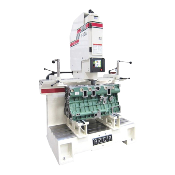
F9A & F10A Operation Manual Description The model F9A & F10A is a precision, single point high-speed boring unit. The F9A & F10A can be equipped with tooling and accessories for re-boring most American passenger car and truck engines, In-lines, as well as 90 and 60 degree V-types. -
Page 8: Limited Warranty
Should a product not be as warranted, Rottler sole obligation shall be, at its option, to repair, correct or replace the product or to refund the amounts paid for the Product upon its return to a location designated by Rottler. -
Page 9: Online Documentation Access
Online Documentation Access Online documentation for machines and optional equipment, including manuals and catalogs, can be accessed at the Rottler website. To access documentation open your browser and navigate to https://www.rottlermfg.com. Scroll to the bottom of the page and under the Owner Resources title click the type of documentation you want to access. - Page 10 Section 1: Introduction F9A & F10A Operation Manual 8029 S 200th Street, Kent, WA 98032 USA | www.rottlermfg.com | Ph: (253) 872-7050 | Fax: (253) 393-0230 Rev 092621...
- Page 11 Machine Operator ......................3-5 Emergency Procedure ....................3-6 Computer and Controller System Safety ..............3-6 Electrical Safety Features Of Rottler DM Controlled Machines ......3-7 8029 S 200th Street, Kent, WA 98032 USA | www.rottlermfg.com | Ph: (253) 872-7050 | Fax: (253) 393-0230 Rev 092621...
-
Page 12: Safety Information
Section 2: Safety F9A & F10A Operation Manual Safety Information For Your Own Safety Read This Instruction Manual Before Operating This Machine. This is the safety alert symbol. It is used to alert you to potential personal injury hazards. Obey all safety messages that follow this symbol to avoid possible injury or death. - Page 13 DO NOT MODIFY OR ALTER THIS EQUIPMENT in any way. If modifications are deemed necessary, all such requests must be approved and/or handled by Rottler Manufacturing. Unauthorized modifications could cause injury and/or damage to machine and will void the warranty.
-
Page 14: Electrical Power
Section 2: Safety F9A & F10A Operation Manual No list of safety guidelines can be complete. Every piece of shop environment is different. Always consider safety first, as it applies to your individual working conditions. Use this and other machinery with caution and respect. Failure to follow guidelines could result in serious personal injury, damage to equipment or poor work results. -
Page 15: Machine Operator
Section 2: Safety F9A & F10A Operation Manual No single list of electrical guidelines can be comprehensive for all shop environments. Operating this machinery may require additional electrical upgrades specific to your shop environment. It is your responsibility to make sure your electrical system comply with all local codes and ordinances. -
Page 16: Emergency Procedure
Wireless using a USB wireless (Wi-Fi) adapter. Updating the Rottler software should ONLY be done when directed to do so by a Rottler service technician. Updating Rottler Software when not directed by Rottler personnel will result in a non-operational machine. -
Page 17: Electrical Safety Features Of Rottler Dm Controlled Machines
NULL and VOID. Electrical Safety Features Of Rottler DM Controlled Machines All Rottler machines that use the DM operational control system are designed to comply with all applicable safety standards. This includes but is not limited to the following systems: Thermal sensors in all motors and motor controls. - Page 18 Section 3: Control Definitions F9A & F10A Operations Manual CONTROL DEFINITIONS Contents Control Definitions ..........................4-1 Computer and Controller System Safety for DM Controlled Machines: ..........4-1 Common interface notice ........................4-2 Master Power On/Off Switch ......................... 4-2 Initialization Screen ..........................4-3 General Information ..........................4-3 Home ..............................4-3...
-
Page 19: Control Definitions
Ethernet or Wireless using a USB wireless (Wi-Fi) adapter. Updating the Rottler software should ONLY be done when directed to do so by a Rottler service technician. Updating Rottler Software when not directed by Rottler personnel could result in a non-operational machine. -
Page 20: Master Power On/Off Switch
This will shut down the computer. It is now OK to turn Main Power off to the machine. Initialization Screen When the F9A & F10A is powered up the Rottler program will not automatically start. It may take several minutes for the computer to power. Start the Rottler program by double tapping the Rottler_WPF icon on the desktop Once the program is started, the Rottler Program Select will appear. -
Page 21: General Information
F9A & F10A Operations Manual General Information The Rottler software operates on a Block Model format. You select or create the block you are working with. Then select or create an operation to be performed on that block. The following are descriptions of the functions of the different buttons that appear on the display screen after the system has loaded. -
Page 22: Definitions Of Control Buttons
Section 3: Control Definitions F9A & F10A Operations Manual Definitions of Control Buttons Program Select This button will bring you back to the home screen. The Program Select section of the home screen is located above the spindle control buttons. This is where you create programs for boring different type of blocks. -
Page 23: Options
You can also create a new mode and rename if for a specific use. Pressing this button will bring up a dialog box with Rottler standard operations. 8029 S 200th Street, Kent, WA 98032 USA | www.rottlermfg.com | Ph: (253) 872-7050 | Fax: (253) 393-0230... - Page 24 Section 3: Control Definitions F9A & F10A Operations Manual Select the operation you want to create and then press OK . This will place a Bore operation under the Cylinder bore mode in the right hand section. To enter Bore mode highlight it and then press Select. This will take you to the operation screens that will be described later.
-
Page 25: Std (Standard) Setup
Section 3: Control Definitions F9A & F10A Operations Manual Std (Standard) Setup Pressing this button will insert all the Rottler operations into the right hand section automatically. Options This button is not used on this machine. Delete This will delete the selected Mode. It will ask you if you want this mode deleted before deleting it. NOTE: Once the control definition for a particular button has been discussed it will not be repeated in the different modes of operation. -
Page 26: Handwheel Buttons
Section 3: Control Definitions F9A & F10A Operations Manual Handwheel Buttons .010 button allows the operator to use the hand wheel to move the spindle up or down at .010” per click in either direction. .001 button allows the operator to use the hand wheel to move the spindle up or down at .001” per click in either direction. -
Page 27: Feed Rate
Section 3: Control Definitions F9A & F10A Operations Manual Feed Rate Operator clicks the box to the right to enter desired feed rate. Wherever there is number box where a value can be entered, pressing value box will activate a pop up number pad to input values. -
Page 28: Centering Height Move
Section 3: Control Definitions 3-10 F9A & F10A Operations Manual Centering Height MOVE This button is pressed to cause the spindle to move up or down to the indicated position in the window to the left. Auto Center This button is pressed to cause the machine to float the spindle base, extend the centering fingers, clamp the spindle base, and then retract the centering fingers. -
Page 29: Options Screen
Section 3: Control Definitions 3-11 F9A & F10A Operations Manual Options Screen Finish RPMs default value is 125. When the machine reaches the Finish Cutting Depth the spindle RPMs change to this speed, rotate the number of times set by the Finish Revolutions parameter and index the tool to the index position. - Page 30 Section 3: Control Definitions F9A & F10A Operations Manual OPERATING INSTRUCTIONS Contents Operating Instructions …....................5-1 Home Screen......................... 5-2 Block Select ........................5-3 Mode Select........................5-6 Operation Screen…....................... 5-8 Loading Blocks: Small Gas and Diesel ..............5-13 Manual V6/V8 Combination Fixture ................5-13 Normal Operating Procedure ..................
-
Page 31: Operating Instructions
Windows 7 screen with the Rottler logo will be displayed. Go to HOME screen by double clicking the icon that’s labeled Double Click to Start Rottler. A SelectLanguage pop window will appear. Choose the language to be used, click the button Use the selected language and then click OK. -
Page 32: Home Screen
Section 3: Control Definitions F9A & F10A Operations Manual Home Screen The Home screen will then appear on the display. Program Select section of screen click an existing block program or New to create a new program. Block Select If New is selected a new window will open to enter to block information. Enter with keyboard Block Name, Number of Cylinders, and select either VBlock or Inline. - Page 33 Section 3: Control Definitions F9A & F10A Operations Manual The Home screen will now show the new block you have entered. NOTE: If this machine is located in country that uses the metric system you can switch to metric values.
-
Page 34: Mode Select
Section 3: Control Definitions F9A & F10A Operations Manual Click on the Setup Software tab again and confirm that the metric tab is checked. You can also change the Operating System language by clicking on the Select Language tab and select a language. - Page 35 Section 3: Control Definitions F9A & F10A Operations Manual Mode Select section of screen will now show the Bore process. Click on Bore to select and highlight it. Click Select button. A Homing Warning screen will appear. This warning is for multi axis machines and does not apply to this machine.
-
Page 36: Operation Screen
Section 3: Control Definitions F9A & F10A Operations Manual Operation Screen This will show which program is loaded into memory and all the settings from that program. Since this a new program, you will have to enter all the values before running the bore process. - Page 37 Section 3: Control Definitions F9A & F10A Operations Manual Click WORKHEAD FLOAT button to activate air float. The WORKHEAD FLOAT button will turn red to indicate that the air float is active. Move cutterhead over the first cylinder to be bored. Push WORKHEAD CLAMP button again to deactivate float and lock the workhead.
- Page 38 Section 3: Control Definitions F9A & F10A Operations Manual Move spindle up until bottom of cutterhead clears deck. Push and hold SET Start Cutting Height button until value appears in the value box. This is the height at which the cutterhead will start rotating when the spindle motor is turned on.
- Page 39 Section 3: Control Definitions 3-10 F9A & F10A Operations Manual Lower the cutterhead into the bore. Click Auto Center button. Warning: Do not press Auto Center Button if cutterhead is not in the cylinder bore. This will cause the WORKHEAD FLOAT button to turn red indicating that the air float is active.
-
Page 40: Loading Blocks: Small Gas And Diesel
Section 3: Control Definitions 3-11 F9A & F10A Operations Manual cutterhead into the bore. After the boring process has finished the spindle will stop and the cutterhead will rotate to the home position. The spindle will then move to the Clearance Height to finish the automated process. -
Page 41: Normal Operating Procedure
Section 3: Control Definitions 3-12 F9A & F10A Operations Manual This fixture may be easily repositioned on the support parallels (without a block in place) to shift from the 60 degree support surface to the 90 degree support surface or vice versa. -
Page 42: Retrofitting 502-1-15C Parallels To V6/V8 Combination Fixture
Section 3: Control Definitions 3-13 F9A & F10A Operations Manual Make sure the block is firmly seated in place and not resting on pan-rail burrs or other interference points. Accurate seating can also be a problem with extremely warped, distorted blocks. Another cause of problems is failure to remove main bearing inserts. - Page 43 Section 3: Control Definitions 3-14 F9A & F10A Operations Manual Some V-6 engine blocks (for example Buick V-6) have main bearing bores that are too low in respect to the pan rails. This presents a problem of the locator bar bottoming out in the bar positioners before the block is properly clamped.
-
Page 44: General Machine Information
F9A & F10A Operations Manual General Machine Information Before starting to build or use any of the Rottler operating programs it is important to understand how the machine operates internally. The Rottler F9A & F10A model uses Computerized Numeric Control (CNC). The CNC is always operating when the machine is turned on. - Page 45 Section 3: Control Definitions 3-16 F9A & F10A Operations Manual Thoroughly clean the end, including the threads, of the cutterhead that is going to be installed. Line up the key in the cutterhead, with the key way in the inner spindle and lift the cutterhead in.
-
Page 46: Backing Up And Restoring Block Profiles
Section 3: Control Definitions 3-17 F9A & F10A Operations Manual Backing Up and Restoring Block Profiles This section will explain how to back up and restore the operator created block profiles for DM controlled machines for archival purposes or to transfer to a different machine. - Page 47 Section 3: Control Definitions 3-18 F9A & F10A Operations Manual The following pop up box will appear on your screen. Click on the Open folder to view files option and the following screen will appear. This is the contents of the flash drive you just plugged in.
- Page 48 Section 3: Control Definitions 3-19 F9A & F10A Operations Manual Next resize and arrange both file browsers so that they are side by side. Block profiles are backed up each time the machine is run with the current profiles being shown in the RottlerWPF folder.
- Page 49 Section 3: Control Definitions 3-20 F9A & F10A Operations Manual To restore or add block profiles go through the first 5 steps explained previously. Highlight the block profiles file in the flash drive and drag it into the RottlerWPF folder on the local hard drive.
- Page 50 Section 3: Control Definitions 3-21 F9A & F10A Operations Manual The archived block profiles will now be installed. Close both browser windows and remove the flash drive. The restore process is now complete. 8029 S 200th Street, Kent, WA 98032 USA | www.rottlermfg.com | Ph: (253) 872-7050 | Fax: (253) 393-0230...
Need help?
Do you have a question about the F9A and is the answer not in the manual?
Questions and answers