
Subscribe to Our Youtube Channel
Related Manuals for Rottler SG10XY


Summary of Contents for Rottler SG10XY
- Page 1 OPERATION AND MAINTENANCE MANUAL 8029 S 200th St. Kent, WA 98032 USA | www.rottlermfg.com | Ph: 253-872-7050 | Fax: 253-395-0230 04.01.2019...
- Page 3 Contact your regional Rottler sales rep for assistance in ordering optional equipment, replacement parts, or tooling. If you are unable to contact your regional Rottler sales rep, call the factory at 253-872-7050 and ask to speak to the parts sales specialist.
-
Page 5: Table Of Contents
Section 1 Introduction SG9MTS Manual INTRODUCTION Contents Introduction ........................1-1 Description ........................1-2 Disclaimer ........................1-2 Limited Warranty ......................1-3 Online Documentation Access ...................1-4 www.rottlermfg.com... -
Page 6: Introduction
“Installation Report” located in the Installation Chapter of this manual. We suggest that the new user of the SG10XY read the CONTROL DEFINITIONS to get an idea how the machine operates. The Operating Instructions chapter should be read in order to familiarize the user with the actual button pushing sequences required to carry out a job. -
Page 7: Description
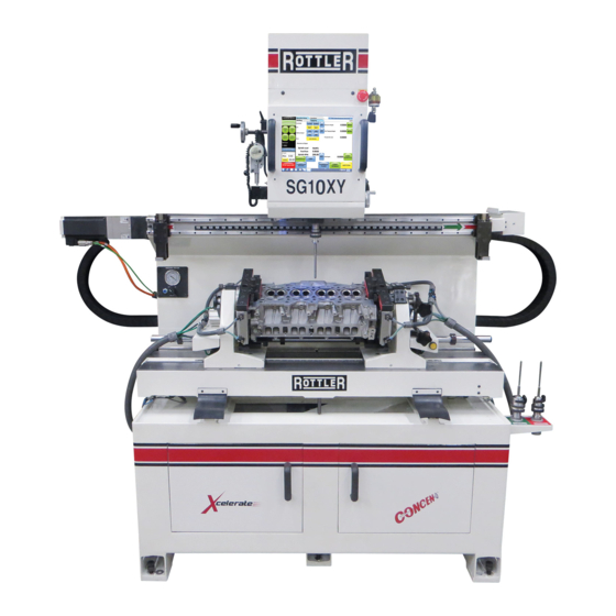
SG9MTS Manual Description The Rottler SG10XY ACTIV spindle is mounted on a sphere which allows the UNIPILOT to automatically center with the valve guide centerline while the Workhead is floating on air cushions. Once air floating stops and the Workhead clamps, the UNIPILOT and valve guide centerline are maintained while cutting the valve seat. -
Page 8: Limited Warranty
Should a product not be as warranted, Rottler sole obligation shall be, at its option, to repair, correct or replace the product or to refund the amounts paid for the Product upon its return to a location designated by Rottler. -
Page 9: Online Documentation Access
SG9MTS Manual Online Documentation Access Online documentation for machines and optional equipment can be accessed at the Rottler website. To access documentation open your browser and navigate to https://www.rottlermfg.com. Scroll to the bottom of the page and under the Owner Resources title click the type of documentation you want to access. - Page 10 Section 1 Introduction SG9MTS Manual www.rottlermfg.com...
- Page 11 Section 2 Installation SG10XY Manual INSTALLATION Contents INSTALLATION REPORT .....................2-2 Installation Procedure ....................2-6 Unpacking and Lifting ......................2-6 Removing Shipping Brackets ....................2-7 Machine Dimensions ......................2-8 Clearance Dimensions ......................2-9 Preparation for Placement ....................2-10 Machine Installation ......................2-10 Positioning the Machine .....................2-11...
- Page 12 Section 2 Installation SG10XY Manual ATTENTION OWNER/BUSINESS MANAGER To validate the warranty on your new Rottler machine, please be sure to sign the installation report after the installation technician has installed the machine and verified the machine is operating correctly and given the operators operation and maintenance training.
-
Page 13: Installation Report
L1 to ground _________VAC L2 to ground __________VAC. Make sure all electrical equipment has the proper overload protection. The SG10XY should have a fully isolated power supply to prevent damage and uncontrolled movement of the machine. If the SG10XY is on the same power lines that are running to other electrical equipment (grinders, welders, and other AC motors) electrical noise can be induced into the SG10XY electrical system. - Page 14 ______Once the machine has been fully setup and is ready for operation create a Skype account for the machine following the instructions in the Installation Section of the manual. ______Explain to the customer and the operator how the to log onto Skype and communicate with Rottler when needed.
- Page 15 Section 2 Installation SG10XY Manual ______Explain to the customer the proper way for turn the machine off when it is not in use. Do not leave the machine on overnight. It is important to close all programs followed by shutting down Windows before turning the main power switch off.
- Page 16 Rottler equipment. It is the responsibility of the end user of Rottler equipment to determine the final dimensions and finishes of the workpiece that they are working on. Any information regarding final dimensions and...
-
Page 17: Installation Procedure
The proper loading arrangement and location for your SG10XY machine is extremely important. A slow travel (6 to 10 feet / min.) power hoist operated from either a bridge crane or a jib crane arrangement works very well. -
Page 18: Removing Shipping Brackets
Section 2 Installation SG10XY Manual Removing Shipping Brackets Before leveling the machine, loosen and remove the all shipping brackets and bolts. (Figures 1 – 5) www.rottlermfg.com... -
Page 19: Machine Dimensions
Section 2 Installation SG10XY Manual Machine Dimensions www.rottlermfg.com... -
Page 20: Clearance Dimensions
Section 2 Installation SG10XY Manual Clearance Dimensions Requird Clearances 110” 78” www.rottlermfg.com... -
Page 21: Preparation For Placement
Section 2 Installation 2-10 SG10XY Manual Preparation for Placement Air supply is connected at the left side of the machine, at base of lower casting. Connection can either be a quick disconnect or permanent threaded connection. Be certain to use an adequately sized airline, permitting proper operation of float. -
Page 22: Positioning The Machine
Section 2 Installation 2-11 SG10XY Manual Positioning the Machine • Lift Machine using a fork lift. Move fork lift to front of Machine and separate forks so they are visually centered. • Insert forks under front-center of Machine, using care not to damage Foot Pedals Valve or Air Lines. -
Page 23: Leveling The Machine
Section 2 Installation 2-12 SG10XY Manual Leveling the Machine Use required machinist level. (Starret 98 or better). NOTE: Rotate Level 180º to check that Level is properly adjusted. If Level does not read same in both directions, recalibrate level. Use the level on the upper float surface, level the machine as precisely as possible, front to back and side to side. -
Page 24: Air Supply
Air Supply It is very important the air source for the SG10XY machine be moisture free. Water and oil in the line will result in early cylinder and valve failure. The factory recommends installing a water trap at the machine. -
Page 25: Power Supply
Section 2 Installation 2-14 SG10XY Manual Power Supply This machine has the following power requirements: • 208 to 240 VAC • Single Phase Power • 50 or 60 Hz • 30 Amps See illustration below for correct connection of incoming power. Measured power at the machine’s main breaker must be within the required range listed above. -
Page 26: Grounding
Section 2 Installation 2-15 SG10XY Manual Grounding The machine requires a good earth ground. The grounding conductor from the incoming power source must be connected to the grounding block located inside of the electrical cabinet. A ground rod installed in addition to the electrical service grounding conductor is permitted, but must be connected directly to the grounding block inside of the electrical cabinet. -
Page 27: Creating A Skype Account
Section 2 Installation 2-16 SG10XY Manual Creating a Skype Account Click on create an account Click on: Use your email instead Click on: Get new email address www.rottlermfg.com... - Page 28 Section 2 Installation 2-17 SG10XY Manual Name the email account using the Rottler machine Model and Serial number. Ex: H85A111, EM69P001 Create a password that is easy to remember. Uncheck the box to receive emails from Microsoft. First Name: Model-Serial Number...
- Page 29 Section 2 Installation 2-18 SG10XY Manual Type the code exactly as it appears. Click “Next” Click “Continue” If your headset and/or web camera are hooked up you can verify that they are working here. Otherwise, click “Continue” www.rottlermfg.com...
- Page 30 Section 2 Installation 2-19 SG10XY Manual Click “Add later” to skip this part. Your Skype account is set up and ready for use. www.rottlermfg.com...
- Page 31 Safety Information .......................3-1 Safety Instructions for Machine Use .................. 3-1 Electrical Power ........................3-3 Machine Operator ......................... 3-5 Emergency Procedure ......................3-6 Computer and Controller System Safety ................3-6 Electrical Safety Features Of Rottler DM Controlled Machines ........3-7 www.rottlermfg.com...
-
Page 32: Safety Information
Section 3 Safety SG10XY Manual Safety Information For Your Own Safety Read This Instruction Manual Before Operating This Machine. This is the safety alert symbol. It is used to alert you to potential personal injury hazards. Obey all safety messages that follow this symbol to avoid possible injury or death. - Page 33 DO NOT MODIFY OR ALTER THIS EQUIPMENT in any way. If modifications are deemed necessary, all such requests must be approved and/or handled by Rottler Manufacturing. Unauthorized modifications could cause injury and/or damage to machine and will void the warranty.
-
Page 34: Electrical Power
Section 3 Safety SG10XY Manual SAFETY DECALS SHOULD NEVER BE REMOVED. They are there to convey important safety information and warn of potential hazards. ALL LOCAL SAFETY CODES AND REGULATIONS should be followed when installing this machine. ONLY QUALIFIED PERSONAL should perform service on the electrical and control systems. - Page 35 Section 3 Safety SG10XY Manual In the event of an electrical short, grounding reduces the risk of electric shock by providing a path of least resistance to disperse electric current. Electrocution or a fire can result if the machine is not grounded correctly. Make sure the ground is connected in accordance with this manual.
-
Page 36: Machine Operator
Section 3 Safety SG10XY Manual Machine Operator The operator of this machine should be a skilled machinist craftsman who is well versed in the caution, care, and knowledge required to safely operate metal cutting tools. If the operator is not a skilled machinist he/she must pay strict attention to the Operating Instructions outlined in this manual, and get instruction from a qualified machinist in both production and operation of this machine. -
Page 37: Emergency Procedure
Ethernet or Wireless using a USB wireless (Wi-Fi) adapter. Updating the Rottler software should ONLY be done when directed to do so by a Rottler service technician. Updating Rottler Software when not directed by Rottler personnel will result in a non-operational machine. -
Page 38: Electrical Safety Features Of Rottler Dm Controlled Machines
SG10XY Manual Electrical Safety Features Of Rottler DM Controlled Machines All Rottler machines that use the DM operational control system are designed to comply with all applicable safety standards. This includes but is not limited to the following systems: •... - Page 39 Section 4 Control Definitions SG10XY Manual CONTROL DEFINITIONS Contents Control Definitions ......................4-1 Computer and Controller System Safety for DM Controlled Machines ......4-1 COMMON INTERFACE NOTICE ..................4-2 Master Power On/Off Switch ....................4-2 Initialization Screen ......................4-2 Homing ...............................4-3 Program select Buttons ....................... 4-5 Rapid Up / Rapid Down ........................4-5...
- Page 40 Section 4 Control Definitions SG10XY Manual Reaming Program: Operations Screen ................4-9 Vertical Zero ............................4-9 Start Cutting Height ..........................4-9 Finish Cutting Depth .........................4-9 Options Screen ........................4-10 Dwell Options ..........................4-10 Retract Out Options ........................4-10 Peck Options ...........................4-10 Head Property Screen ......................4-11 General Information ......................4-11...
-
Page 41: Control Definitions
SG10XY Manual Control Definitions NOTE: It is important that the operator of the SG10XY read the Control Definitions chapter in this manual before proceeding any further. The purpose of this chapter is to define the function of the buttons throughout the various screens. -
Page 42: Common Interface Notice
When first applying power to the machine the computer will need to boot up. Be patient, it will take several minutes to complete booting. The Rottler program will not automatically start. Double tap the Rottler_WPF icon on the screen to start Rottler. When turning the main power to the machine off there is a specific procedure to follow so as not to damage the computer. -
Page 43: Homing
1st thing you want to do when this screen appears is to HOME the machine. Buy pressing this button the computer will sync itself with the motors. This process must be done each time the SG10XY has been shut off and restarted. If the HOME process is not done the machine will not operate. - Page 44 Section 4 Control Definitions SG10XY Manual Next press NEW under program select. Enter in the head name you are going to work on. (To do this either plug in the supplied keyboard or click on the on screen keyboard in the taskbar.) Then click OK After this click on Std.
-
Page 45: Program Select Buttons
Section 4 Control Definitions SG10XY Manual Program select Buttons These buttons work in all modes. Rapid Up / Rapid Down These buttons will move the spindle up or down quickly, it will stop when released. Feed Up / Feed Down These buttons will move the spindle up or down slowly, it will stop when released. -
Page 46: Lamp
Section 4 Control Definitions SG10XY Manual LAMP Turns work light on and off Center pilot Locks and unlocks spindle sphere WORKHEAD FLOAT Floats workhead when pushed RED and clamps when pushed BLUE START SPINDLE Turns spindle on and off. SAFE STOP Immediately stops downward feed and goes to finish options mode HANDWHEEL: 0.0100 / 0.0010... -
Page 47: Seat Cut: Operations Screen
Section 4 Control Definitions SG10XY Manual Seat Cut: Operations screen Vertical Zero This is the first step you need to do to set up your program. All of the height figures entered will start from this position. This number represents the spindle vertical position. The “zero” position is when the cutting insert first comes in contact with the seat it is cutting. -
Page 48: Setting The Rest Of The Heights
Section 4 Control Definitions SG10XY Manual Setting The Rest Of The Heights Raise the spindle with the rapid up or feed up button until the end of the pilot (using unipilot system) or cutter head (std. system) clears and can float guide to guide without interference, press and hold the “HEAD CLEARANCE HEIGHT “... -
Page 49: Reaming Program: Operations Screen
Section 4 Control Definitions SG10XY Manual Reaming Program: Operations Screen Vertical Zero Set this height when tip of reamer just contacts head surface or top of guide. Your choice. HEAD CLEARANCE HEIGHT and RAPID TO VALVE GUIDE HEIGHT is same as previously described. -
Page 50: Options Screen
Section 4 Control Definitions 4-10 SG10XY Manual Options Screen Dwell Options After finish “cutting depth” in the “seat cutting” and “seat counter boring” mode the “dwell options” go into effect. This means that after the finish cutting depth has been reached the machine will go to this stage. -
Page 51: Head Property Screen
In this page you can enter in all head information, it will be saved into the head program you are in. General Information Once selected, all operations of the SG10XY can perform are stored in that Cylinder Head model. The following is a more detailed list on the head selecting screen. -
Page 52: Options
Section 4 Control Definitions 4-12 SG10XY Manual Options To edit a mode select name click here and use keyboard to change. Example – change “Seat Cut” to “Seat Cut INTAKE” or just” INTAKE” press OK when done. Delete To delete an operation simply highlight and press delete. . The screen will ask you if you want to delete the operation. - Page 53 OPERATING INSTRUCTIONS Contents Operating Instructions ....................5-1 Mounting Tool Sharpener ....................5-1 Rottler Tool Bit Sharpener ....................5-1 Built In Venturi Vacuum Tester .................... 5-1 Mounting Cylinder Heads ...................5-2 360 Degree Rollover Fixtures ....................5-2 Overhead Cam C Clamp System ..................5-3 Alignment and Setup ......................
- Page 54 How to Use UPT Series Uipilot Toolholders ............5-14 Using the Unipilot System for the UPT5200 / UPT5400 Series Tool Holders ..5-16 Rottler Six and One Instructions ..................5-17 Adjusting the Square Carbide Inserts ................5-20 Cutting Small Diameter Valve Seats ................. 5-21 Backing Up and Restoring Block Profiles...............5-22...
-
Page 55: Operating Instructions
Mount tool sharpener on right hand side of machine using the cap screw provided with machine. Rottler Tool Bit Sharpener When you sharpener the Rottler form Carbide bits, consists in restoring the tool cutting angle by grinding the face. To sharp the carbide bit must be fitted on the bit holder also fitted on the tool holder. -
Page 56: Mounting Cylinder Heads
Section 5 Operating Instructions SG10XY Manual Mounting Cylinder Heads 360 Degree Rollover Fixtures Initial clamp height adjustments to the head trunnions can be accomplished by measuring the head thickness then raising the turning clamping block assembly to the appropriate height using the clamping block acme screws. -
Page 57: Overhead Cam C Clamp System
Section 5 Operating Instructions SG10XY Manual Overhead Cam C Clamp System Using 10mm Allen wrench, remove the existing lower fixed plate on the 360 degree fixture (left and right) Install the C Clamp, you must use the two bolts included with the fixture and make sure is good and tight The cylinder head gasket surface must be against the machined surface of the U Clamp Fixture;... - Page 58 Section 5 Operating Instructions SG10XY Manual The Quick-Clamp frame is mounted between the trunnions and clamped using the clamping plates. (See Pictures) The cylinder head is then held to the frame with the swivel clamp assemblies through the appropriate head bolt holes or used the standard clamp plates.
-
Page 59: Alignment And Setup
Section 5 Operating Instructions SG10XY Manual Alignment and Setup Alignment and setup applies to both the cylinder head and the machine’s floating head. The goal is to get perfectly align to the spindle centerline of the area of the head to be machined. Most machining operations on cylinder heads use the valve guide centerline as the reference point so we will use that as an example. -
Page 60: Canted Valve Cylinder Heads (Automotive Application)
The bar is held against two pilots in two adjacent guides. Use the alignment post to adjust the angle. (See Picture) NOTE: It is important that the operator of the SG10XY read the Control Definitions chapter in this manual before proceeding any further. -
Page 61: Three Angle Seat Cutting
The capacity of the Rottler SG80A associated with a complete tooling range allow working on seats of diameters up to 210 millimeters (8.25”). -
Page 62: Checking Working Range Of Uni-Pilot
Section 5 Operating Instructions SG10XY Manual Checking Working Range of UNI-PILOT Checking Procedure Insert Standard 3/8 (9.52mm) Shank diameter UNI-PILOT in the cylinder head valve guide. Place checking gauge along pilot section that is exposed above cylinder head surface. If pilot top is within Min & Max range of the gauge, then you may proceed with machining seat. -
Page 63: Checking Valve Seat Concentricity
Section 5 Operating Instructions SG10XY Manual Checking Valve Seat Concentricity Make sure pilot and valve seat to be measured are free from dust, burrs, etc. A drop of oil or similar lubricant on valve seat will aid measuring. Loosen brass locking screw and lower dial gauge down over pilot. -
Page 64: Machining Seats
Section 5 Operating Instructions 5-10 SG10XY Manual Machining Seats 1. After all height settings are made, you now are ready to cut seats. Cut counter bores 2. Set “feed rate”.0008 is a good starting point. 3. Set “spindle RPM” 400 is a good starting point. -
Page 65: Changing The Spindle Adapters
Installing the Spherical self Aligning Toolholder Once the spring free adapter is in the spindle, fit the Rottler Spherical Self aligning Tool holder assembly into the spindle adapter; make sure to align the locator pins before you fit it into the spindle adapter and push it until you feel that is lock. -
Page 66: Unipilot Centralizing Pilots
UCP0700 (0.2756”). Shank Diameter The part of the pilot that fits inside the tool holder is referred to as the shank. Rottler offers three different shank sizes (6.00mm, 9.52mm, and 20.00mm). For longest tool life and best seat cutting results, the shank needs to go as far as possible inside the tool holder when cutting valve seats or boring out valve seat housings. -
Page 67: Carbide Inserts
Modular Carbide Centralizing Pilot System for Valve Guides Over 0.875” (22.23mm) Rottler also offers a modular carbide centralizing pilot system for very large engine applications. This system is versatile because it allows you to use different size sleeves, which are adjustable for different lengths, for different applications while using only one pilot. -
Page 68: How To Use Upt Series Uipilot Toolholders
Section 5 Operating Instructions 5-14 SG10XY Manual How to Use UPT Series Uipilot Toolholders 1. Pilot shank and toolholder Inside Diameter for the pilot shank must be clean from cast iron dust, few drops on lite oil may be necessary at least twice a day. - Page 69 Section 5 Operating Instructions 5-15 SG10XY Manual This is the correct way to lock the Insert holder using the long part of the Allen wrench like you see on the picture below to avoid too much torque and collapse the Pilot shank ID Bore of the Toolholder.
-
Page 70: Using The Unipilot System For The Upt5200 / Upt5400 Series Tool Holders
Section 5 Operating Instructions 5-16 SG10XY Manual Using the Unipilot System for the UPT5200 / UPT5400 Series Tool Holders 1. Insert standard 3/8” (9.52mm) shank UNIPILOT into the cylinder head valve guide. 2. Place checking gage next to Pilot shank to inspect range. -
Page 71: Rottler Six And One Instructions
Section 5 Operating Instructions 5-17 SG10XY Manual Rottler Six and One Instructions www.rottlermfg.com... - Page 72 Section 5 Operating Instructions 5-18 SG10XY Manual www.rottlermfg.com...
- Page 73 Section 5 Operating Instructions 5-19 SG10XY Manual www.rottlermfg.com...
-
Page 74: Adjusting The Square Carbide Inserts
Section 5 Operating Instructions 5-20 SG10XY Manual Adjusting the Square Carbide Inserts • The micrometer should be used. • Set the Digital micrometer (BM) according to the valve seat insert diameter and the required interference. • Slide the tool holder without the pilot on the micrometer. -
Page 75: Cutting Small Diameter Valve Seats
Section 5 Operating Instructions 5-21 SG10XY Manual Cutting Small Diameter Valve Seats The UPT5200 adapter has a set screw as shown in photo below – push pilot all the way into the UPT5200 and tighten set screw to hold pilot inside the UPT5200. Install the Tip Holder TH1999, adjust diameter, release set screw, and remove pilot. -
Page 76: Backing Up And Restoring Block Profiles
Section 5 Operating Instructions 5-22 SG10XY Manual Backing Up and Restoring Block Profiles This section will explain how to back up and restore the operator created block profiles for DM controlled machines for archival purposes or to transfer to a different machine. - Page 77 Section 5 Operating Instructions 5-23 SG10XY Manual The following pop up box will appear on your screen. Click on the Open folder to view files option and the following screen will appear. This is the contents of the flash drive you just plugged in.
- Page 78 Section 5 Operating Instructions 5-24 SG10XY Manual Next resize and arrange both file browsers so that they are side by side. www.rottlermfg.com...
- Page 79 Section 5 Operating Instructions 5-25 SG10XY Manual Block profiles are backed up each time the machine is run with the current profiles being shown in the RottlerWPF folder. All that needs to be done to back up the current profile is to simply drag it from the RottlerWPF folder to the flash drive folder.
- Page 80 Section 5 Operating Instructions 5-26 SG10XY Manual To restore or add block profiles go through the first 5 steps explained previously. Highlight the block profiles file in the flash drive and drag it into the RottlerWPF folder on the local hard drive.
- Page 81 Section 5 Operating Instructions 5-27 SG10XY Manual You will get a pop up window about there being a file of the same name in the destination folder. Click on the Copy and Replace option. www.rottlermfg.com...
- Page 82 Section 5 Operating Instructions 5-28 SG10XY Manual The archived block profiles will now be installed. Close both browser windows and remove the flash drive. The restore process is now complete. www.rottlermfg.com...
-
Page 83: Tooling For Counterboring Small Diameter Valve Seat Pockets
Bore diameter: 1.270” – 1.580” (32.26 mm – 40.15 Bore diameter: 1.000” – 1.280” (25.42 mm – 32.51 Rottler can also provide Fixed Milling Heads to cut valve seat pockets. They are available in fixed diameters from 1.000” to 2.250” in .0625” increments... - Page 84 Section 5 Operating Instructions 5-30 SG10XY Manual www.rottlermfg.com...
- Page 85 Section 6 Maintenance SG10AXY Manual MAINTENANCE Contents Maintenance .........................6-1 Quick Reference Lubrication Chart ..................6-1 Preventative Maintenance Quick Reference Chart ............6-1 Air Adjustments ........................6-2 Float ..............................6-2 Float surfaces ............................6-2 Calibrating the Digital Level ....................6-3 Spindle ........................... 6-3 Rebuilding the UPT5200 Unipilot Holder ................
-
Page 86: Maintenance
Section 6 Maintenance SG10AXY Manual Maintenance Quick Reference Lubrication Chart Refer to the maintenance section in the manual for lubrication location points and instruction. Assembly Frequency Lube Operation R e c o m m e n d e d Date Serviced Lubricant Outer Spindle 8 Hours... -
Page 87: Air Adjustments
Section 6 Maintenance SG10AXY Manual All floating surfaces should be dry and clean do not oil the surfaces, oil will cause the work heat not to float properly. Air Adjustments Float The float regulators are located on the left side of machine base. Marked “Work Head Air Float Adjustment”... -
Page 88: Calibrating The Digital Level
Section 6 Maintenance SG10AXY Manual Calibrating the Digital Level NOTE: Even though the level has been carefully calibrated at the factory, it is a good idea to recheck calibration before putting the machine into service. In the event that the level is dropped or handled roughly then the following recalibration methods should be implemented. -
Page 89: Rebuilding The Upt5200 Unipilot Holder
Section 6 Maintenance SG10AXY Manual Rebuilding the UPT5200 Unipilot Holder Align the pin and push through until To remove the cap unscrew the cap, this cap has left-hand you able get the sleeve up and threads; remove the long spring with the spacing Rod and the remove the components to replace. - Page 90 Section 6 Maintenance SG10AXY Manual www.rottlermfg.com...
-
Page 91: Adjusting And Aligning The Outer Spindle On Sg Models
Section 6 Maintenance SG10AXY Manual Adjusting And Aligning The Outer Spindle On SG Models There are 2 brass guide shoes located on the guide plate on top of the spindle that align the rack gear on the back of the spindle with the pinion gear that moves the spindle up and down. www.rottlermfg.com... -
Page 92: Adjusting Outer Spindle Clearance
Section 6 Maintenance SG10AXY Manual Adjusting Outer Spindle Clearance Loosen the 4 lock bolts. Loosen the 4 adjusting set screws. Clean outer spindle and lubricate – add a few drops of oil to a clean cloth and wipe outer spindle. Starting with the bottom set of lock bolt and adjusting set screws, tighten the lock bolt until there is drag on the spindle when it is move through its range of travel. -
Page 93: Spindle Lock Nut Service Procedure
Section 6 Maintenance SG10AXY Manual Spindle Lock Nut Service Procedure www.rottlermfg.com... -
Page 94: Replacing The Motherboard Battery
Section 6 Maintenance SG10AXY Manual Replacing the Motherboard Battery If computer fails to boot up and you get a CMOS error message on the screen, then the battery on the computer motherboard has failed and needs to be replaced. The following is the procedure for replacing the motherboard battery. Turn off the power on the electrical enclosure and remove the enclosure cover. - Page 95 Section 6 Maintenance 6-10 SG10AXY Manual Locate the computer and check to see that the power light is not on. If it is on turn off the power switch. Note: On some machines it may be necessary to unbolt the computer from the enclosure in order to gain access to the cover screws.
- Page 96 Section 6 Maintenance 6-11 SG10AXY Manual Locate the battery on the motherboard. Push the battery retention clip away from the battery. When the clip is released the battery will pop up. Remove the battery and place new battery in the battery holder. Using your finger tip push down on the battery until the retention clip is in its lock position.
-
Page 97: Setting The Play Of Z-Axis Ball Screw
Section 6 Maintenance 6-12 SG10AXY Manual Setting the Play of Z-Axis Ball Screw www.rottlermfg.com... - Page 98 Section 6 Maintenance 6-13 SG10AXY Manual www.rottlermfg.com...
- Page 99 Please visit the service tab of our web page at Send a Service Request www.rottlermfg.com or contact the Rottler Factory Service at service@rottlermfg.com for assistance and your service request. You may also call Rottler at 1-800-452-0534 or 1-253-872-7050 Please ensure you have the Machine Model and Serial Number available when contacting Rottler for Service www.rottlermfg.com...
- Page 100 Section 7 Troubleshooting SG10XY Manual Problem Possible Cause Solution Workhead Base Insufficient air pressure Set air pressure of supplied line should be minimum 85 PSI ( 6 Bars) Does Not Float Clamping plate does not drop Take the workhead to one end of the of the...
- Page 101 Section 7 Troubleshooting SG10XY Manual Problem Possible Cause Solution Eccentricity Problems Machine is not level Level machine per instructions in Installation section of this manual When Cutting Three Angle Seats Workhead is not floating Be sure that the work head and main...
- Page 102 Section 7 Troubleshooting SG10XY Manual Problem: Icon On Screen Does Not Move To Area Touched. Solution: Follow the procedure below to recalibrate the touchscreen. 1. Get to the Alignment screen. 1. If an Elo icon is available in the tool tray at the lower right side of the desktop, click it, then click Align.
- Page 103 Section 8 Machine Parts SG10XY Manual MACHINE PARTS Contents Machine Parts ......................8-1 Consumable Parts ........................ 8-1 Carbide Inserts ........................8-2 Special Profiles ..........................8-2 Carbide Pilots ............................8-2 Machine Parts ......................8-3 Base Table and Riser Assembly ..................8-3 Base Assembly ........................8-7 Spindle Assembly .......................
-
Page 104: Machine Parts
Section 8 Machine Parts SG10XY Manual Machine Parts Consumable Parts REFERENCE DESCRIPTION SLEEVE R1 Spindle adapter replacement sleeve Diamond Wheel Cutting Bit Sharpener replacement Wheel (3.000" Diameter OD by BSW002 .375" ID) PRW600PIN Replaceable Pins for PRW600 Pilot Removable wrench tool... -
Page 105: Carbide Inserts
Section 8 Machine Parts SG10XY Manual Carbide Inserts See Carbide Insert Catalog for a complete list of Insert Profiles available from Rottler Manufacturing. Special Profiles Special Profile Cutter Inserts can be manufactured to your exact specifications and can include a combination of angles and radius blends. -
Page 106: Machine Parts
Section 8 Machine Parts SG10XY Manual Machine Parts Base Table and Riser Assembly www.rottlermfg.com... - Page 107 Section 8 Machine Parts SG10XY Manual S. NO. PART NO. DRG NO. DESCRIPTION QTY/M /C SG-10XY 10XY-101 10XY-102 RISER 440-102 BUTTON HEAD SCREW (M6x12) 430-822 DOWEL PIN Ø8x40 ALLEN HEAD SCREW M8x35 033-071 PLATE -B X ¼ NPT 430-830 N-22-SW (9301)
- Page 108 Section 8 Machine Parts SG10XY Manual S. NO. PART NO. DRG. NO. DESCRIPTION QTY/M /C SG-10XY PLAI N WASHER (8MM) 440-155 10XY-155 STOPPER 10XY-156 ALLEN HEAD SCREW M3x10 440-157 10XY-157 END STOPPER 10XY-158 CARRIAGE 440-159 10XY-159 RAIL SLIDE 440-160 10XY-160...
- Page 109 Section 8 Machine Parts SG10XY Manual S. NO. PART NO. DRG. NO. DESCRIPTION QTY/M /C SG-10XY 10XY-1-107 MT G. BK T. (COVER L.H. ) 107. 440-189-3 108. 440-284-R 10XY-1-108 COVER 109. 440-285-1 10XY-1-109 SP ACER 110. 10XY-1-110 ALLEN HEAD SCREW M5x20 10XY-1-111 111.
-
Page 110: Base Assembly
Section 8 Machine Parts SG10XY Manual Base Assembly www.rottlermfg.com... - Page 111 Section 8 Machine Parts SG10XY Manual S.NO. PART NO. DRG. NO. DRG.NO. DESCRIPTION QTY/M /C SG-10XY 044(LOCAL) 440-201 10XY-201 BASE VGS-512 VGS-513 PLUG (BRASS ) VGS-505 BALL BRG. (626) 6x19x6 NC-112-I SPHERICALWASHER 440-206 10XY-206 BASE PL ATE 440-207 10XY-207 CLAM P PL ATE...
- Page 112 Section 8 Machine Parts SG10XY Manual S.NO. PART NO. DRG. NO. DRG.NO. DESCRIPTION QTY/M /C SG-10XY 044(LOCAL) VGS-640-1 044-L-255 WASHER 430-670 044-L-256 EYE BOLT NC-35 ECC. CLAM P NC-39 044-L-258 LEV ER PIN 430-802 KNOB (M 8x25) 430-629-1 044-L-260 CLAM P PIN...
-
Page 113: Spindle Assembly
Section 8 Machine Parts 8-10 SG10XY Manual Spindle Assembly TOTAL LEN. 30.125" www.rottlermfg.com... - Page 114 Section 8 Machine Parts 8-11 SG10XY Manual S. NO. PART NO. DRG. NO. DESCRIPTION QTY/M /C SG-10XY NC-151-00 DRIVE SHAFT COMP. ENCLUDED NC-151-C 10XY-301 DRIVE SHAFT ASSY. NCL-71-S SP ACER NCL-72-1 ROTATING PIN NCL-74-1 PLUNGER NCL-72-2 BEARING HOLDER NCL-77 LOWER CONE...
- Page 115 Section 8 Machine Parts 8-12 SG10XY Manual S. NO. PART NO. DRG. NO. DESCRIPTION QTY/M /C SG-10XY NC-37 PLATE (LEVELING PIN) 430-616 LEVELI NG PIN NC-2A-2 10XY-350 OIL FITTING (FOR BALL SCREW) 440-351 10XY-351 FRONT COVER ASSY. NCL-81-2 CYLI NDER COVER...
- Page 116 Section 8 Machine Parts 8-13 SG10XY Manual S. NO. PART NO. DRG. NO. DESCRIPTION QTY/M /C SG-10XY NC-144 THRUST BEARING (12x26x4) NC-142 SP ACER ALLEN HEAD SCREW M6x16 NC-143 SP ACING BLOCK F. PT . GRUB SCREW M5x6 5362 79-B008 AI R CYLI NDER www.rottlermfg.com...
-
Page 117: Transmission Assembly
Section 8 Machine Parts 8-14 SG10XY Manual Transmission Assembly www.rottlermfg.com... - Page 118 Section 8 Machine Parts 8-15 SG10XY Manual S. NO. PART NO. DRG. NO. DESCRIPTIO N QTY/ M/ C SG-10XY NC-155-1 LOCK NUT BALL BEARING (6910-2RS 1) 430-705A ALLEN HEAD SCREW (M6x20) NC-117-2 BEARING HOUSING NC-14-2 10XY-42 TOP PL ATE ALLEN HEAD SCREW M4x16...
-
Page 119: Head Support Assembly
Section 8 Machine Parts 8-16 SG10XY Manual Head Support Assembly www.rottlermfg.com... - Page 120 Section 8 Machine Parts 8-17 SG10XY Manual S. NO. PART NO. DRG. NO. DESCRIPTIO N QTY/M/ C SG-10XY 10XY-501 HEAD SUPPORT LEFT 440-501 440-502 10XY-502 END PIECE 440-503 10XY-503 CYL. MTG. FLAT. 10XY-504 THRUST PAD 440-504 BUSH 430-901 430-911 KNOB...
- Page 121 Section 8 Machine Parts 8-18 SG10XY Manual S. NO. PART NO. DRG. NO. DESCRIPTIO N QTY/M/ C SG-10XY 10XY-556 ALLEN HEAD SCREW (M6x25) 10XY-557 HEX. NUT M6 440-558 10XY-558 STOPPER BLOCK UPPER 440-559 10XY-559 LOCK SCREW 440-560 10XY-560 STOPPER BLOCK FRONT...
- Page 122 Section 8 Machine Parts 8-19 SG10XY Manual DRG. NO. DESCRIPTIO N QTY/M/ C S. NO. PART NO. SG-10XY 10XY-5-110 CLAM P FLAT (L.H & R.H) 440-5110 10XY-5-111 WEDGE STOPPER 440-5111 10XY-5-112 CLAM P FLAT (L.H) 440-5112 10XY-5-113 CLAM P FLAT (R.H)
-
Page 123: Solenoid Valves
Section 8 Machine Parts 8-20 SG10XY Manual Solenoid Valves www.rottlermfg.com... -
Page 124: Pneumatic Circuit Diagram
Section 8 Machine Parts 8-21 SG10XY Manual Pneumatic Circuit Diagram BLACK BLACK www.rottlermfg.com... -
Page 125: Pneumatic Circuit Parts
Section 8 Machine Parts 8-22 SG10XY Manual Pneumatic Circuit Parts PART LIST MA CHINE TYPE: PNEUM ATIC PART S MO DEL : SG-10XY S. NO. PART NO. DESCRIPTION REM ARKS 162721 FILTER REGULATOR LFR-3/8-D-5M-MIDI 11914 BASIC VA LV E SV-5-M5B... -
Page 126: Rbhar1Kit Repair Kit For Rbhar1
Section 8 Machine Parts 8-23 SG10XY Manual RBHAR1KIT Repair Kit for RBHAR1 Item Part # Description Quantity RBHAR1COL Collar 555-19-19 Stop Screw 555-19-20 Dog Point Screw 555-19-21 Ball Point 555-19-22 Detent 555-19-23 Ball Seat 555-19-24 Spring 555-19-25 Ball (4mm) www.rottlermfg.com... -
Page 127: Rbhar40Upckit Repair Kit For Rbhar40Upt
Section 8 Machine Parts 8-24 SG10XY Manual RBHAR40UPCKIT Repair Kit for RBHAR40UPT Item Part # Description Quantity RBHAR40UPCCOL Collar 555-19-19 Stop Screw 555-19-20 Dog Point Screw 555-19-21 Ball Point 555-19-22 Detent 555-19-23 Ball Seat 555-19-24 Spring 555-19-25 Ball (4mm) www.rottlermfg.com... -
Page 128: Electrical Wiring Diagram
Section 8 Machine Parts 8-25 SG10XY Manual Electrical Wiring Diagram WORKLIGHT WORKLIGHT PENDANT ASSEMBLY 6457H 6457H ANGLE HANDWHEEL SENSOR 7610W EMERGENCY STOP 6428 6389D MONITOR THERMAL SWITCH N.C. C13, C14, C15 X-AXIS MOTOR VIDEO, USB1 BSM80C-375AB2 9020N LOWER CABINET SOLENOID PACK THERMAL SWITCH N.C. -
Page 129: Air Line Diagram
Section 8 Machine Parts 8-26 SG10XY Manual Air Line Diagram www.rottlermfg.com... - Page 130 Section 8 Machine Parts 8-27 SG10XY Manual www.rottlermfg.com...
- Page 131 Section 9 Options SG10XY Manual OPTIONS Optional Equipment Optional Equipment Catalog and Parts Manual are located on the Manual CD shipped with machine. www.rottlermfg.com...
- Page 132 Section 9 Options SG10XY Manual www.rottlermfg.com...
- Page 133 A complete list of the Material Data Safety Sheets of substances and materials used by Rottler Manufacturing during manufacturing, testing, and shipping is located on the Manual CD shipped with the machine. Material Data Safety Sheets are also located on the company web site: http://www.rottlermfg.com/documentation.php...
- Page 134 Section 10 Material Data Safety Sheets 10-2 SG10XY Manual www.rottlermfg.com...
- Page 135 Section 10 Material Data Safety Sheets 10-3 SG10XY Manual www.rottlermfg.com...
- Page 136 Section 10 Material Data Safety Sheets 10-4 SG10XY Manual www.rottlermfg.com...
- Page 137 Section 10 Material Data Safety Sheets 10-5 SG10XY Manual www.rottlermfg.com...
- Page 138 Section 10 Material Data Safety Sheets 10-6 SG10XY Manual www.rottlermfg.com...
- Page 139 Section 10 Material Data Safety Sheets 10-7 SG10XY Manual www.rottlermfg.com...
- Page 140 Section 10 Material Data Safety Sheets 10-8 SG10XY Manual www.rottlermfg.com...
- Page 141 Section 10 Material Data Safety Sheets 10-9 SG10XY Manual www.rottlermfg.com...
- Page 142 Section 10 Material Data Safety Sheets 10-10 SG10XY Manual www.rottlermfg.com...
- Page 143 Section 10 Material Data Safety Sheets 10-11 SG10XY Manual www.rottlermfg.com...
- Page 144 Section 10 Material Data Safety Sheets 10-12 SG10XY Manual www.rottlermfg.com...
- Page 145 Section 10 Material Data Safety Sheets 10-13 SG10XY Manual www.rottlermfg.com...
- Page 146 Section 10 Material Data Safety Sheets 10-14 SG10XY Manual www.rottlermfg.com...
Need help?
Do you have a question about the SG10XY and is the answer not in the manual?
Questions and answers