Sign In
Upload
Download
Table of Contents
Contents
Add to my manuals
Delete from my manuals
Share
URL of this page:
HTML Link:
Bookmark this page
Add
Manual will be automatically added to "My Manuals"
Print this page
×
Bookmark added
×
Added to my manuals
Manuals
Brands
Rottler Manuals
Industrial Equipment
SM Series
Operation and maintenance manual
Rottler SM Series Operation And Maintenance Manual
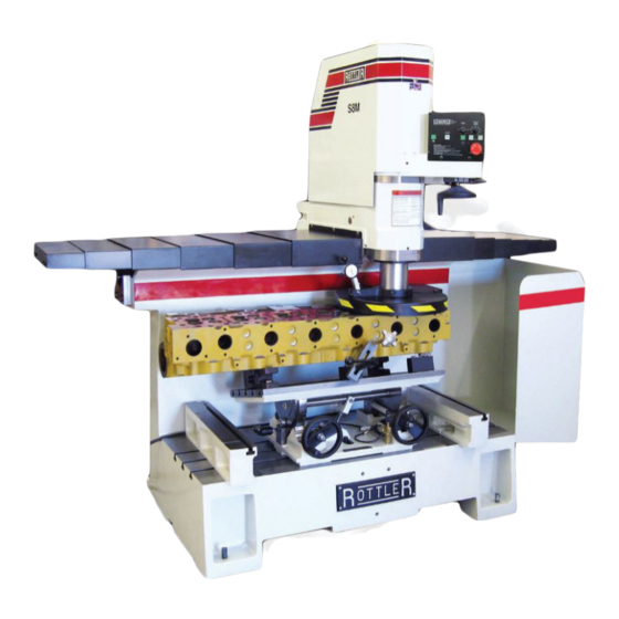
Surfacing machines
Hide thumbs
1
2
3
4
5
6
7
8
9
10
11
12
13
14
15
16
17
18
Table Of Contents
19
20
21
22
23
24
25
26
27
28
29
30
31
32
33
34
35
36
37
38
39
40
41
42
43
44
45
46
47
48
49
50
51
52
53
54
55
56
57
58
59
60
61
62
63
64
65
66
67
68
69
70
71
72
73
74
75
76
77
78
79
80
81
82
83
84
85
86
87
88
89
90
91
92
93
94
95
96
page
of
96
Go
/
96
Contents
Table of Contents
Bookmarks
Table of Contents
Table of Contents
Safety Information
Safety Instructions for Machine Use
Electrical Power
Machine Operator
Emergency Procedure
Operating Instructions
Manual Operation
Operation
General Insert Information
Cutting Speed Calculation
Surfacing Inserts
6303B
6303M
6303U
6303K
Rs322
6301J
1/2" (12.70Mm) Surfacing Inserts
6303P
6303Q
Bi-Metal Surfacing
Cylinder Heads with Protruding Valve Seats
6303S
6303U
6303R
6301I
6301V
Special Toolholder and Insert
7202X
7202Z
Maintenance
Lubrication
Horizontal Ballscrew Nut
Vertical Ballscrew Nut
Outer Spindle
Inner Spindle
Cleaning the Way Surface
Lubrication - Quick Reference Chart
S7M - S8M Machine Lubrication Illustration
Axis Universal Machine Table 7119Q - Lubrication Illustration
Setting Cutting Tool Inserts
Production Cutting
Aluminum & Cast Iron
Dial Indicator Setting
Vertical Travel Belt
Upper Vertical Travel Belt
Drive Belt Replacement
Drive Sprocket / Motor Removal and Replacement
Removal of Drive Sprocket
Replacement of Drive Sprocket
Driven Sprocket Removal and Replacement
Removal of Driven Sprocket
Replacement of Driven Sprocket
Cutterhead and Chip Guard Removal
Upper Housing Removal
Inner Spindle Removal
Upper Spindle Bearing Removal
Spindle Sensor Adjustment
Horizontal Ball Screw and Belt Alignment and Adjustment
Air Adjustment of the S7M - S8M Machine
Air Adjustments Illustration
Pneumatic Control Diagram
Cutterhead Tilt Adjustment
Outer Spindle Adjustment
Inner Spindle Adjustment
Alignment Definitions for Angular Bearings and Belleville Washers
Bearing Alignment
Belleville Washer Alignment
Z-Axis Vertical Ballscrew Lower Bearing Stacking Order
Z-Axis Vertical Ballscrew Lower Bearing Section View
Inner Spindle Upper Section Belleville Washer Stacking Order
Inner Spindle Upper Section Belleville Washer Section View
Inner Spindle Lower Section Bearing Stacking Order
Inner Spindle Lower Section Bearing Section View
Machine Parts
Front / Right Side View S7-8M
Pneumatic Assembly
Electrical Enclosure
Electrical Diagram
Upper Housing
Upper Vertical Travel Belt Parts
Spindle Base Front Section
Inner / Outer Spindle Assembly
Spindle Base Bushings
Spindle Base Assembly
Left Ballscrew Support
Right Ballscrew Support
Home and Limit Switches
Pendant Assembly
Spindle Base
Chip Shield 14" & 16
14" Fly Cutter
Chip Chute
Waycovers and Optional Chip Catcher Assembly
Riser Set
Air Diagram
Advertisement
Quick Links
1
Operating Instructions
Download this manual
OPERATION AND MAINTENANCE MANUAL
8029 S 200th St. Kent, WA 98032 USA | www.rottlermfg.com | Ph: 253-872-7050 | Fax: 253-395-0230
16.03.2017
Table of
Contents
Previous
Page
Next
Page
1
2
3
4
5
Advertisement
Table of Contents
Need help?
Do you have a question about the SM Series and is the answer not in the manual?
Ask a question
Questions and answers
Related Manuals for Rottler SM Series
Industrial Equipment Rottler SG8 Operation And Maintenance Manual
Seat and guide machine (42 pages)
Industrial Equipment Rottler SG80AII Operation And Maintenance Manual
Cylinder head seat and guide machine with activ spindle and cnc control (67 pages)
Industrial Equipment Rottler SA Series Operation And Maintenance Manual
Surfacing machines (94 pages)
Industrial Equipment Rottler S7A Operation And Maintenance Manual
Surfacing machines (94 pages)
Industrial Equipment Rottler S7M Operation And Maintenance Manual
Surfacing machines (96 pages)
Industrial Equipment Rottler S8M Operation And Maintenance Manual
Surfacing machines (96 pages)
Industrial Equipment Rottler SAD Series Operation And Maintenance Manual
Surfacing machines (114 pages)
Industrial Equipment Rottler SG10XY Operation And Maintenance Manual
Cnc cylinder head seat & guide machine with activ spindle (146 pages)
Industrial Equipment Rottler SG9A Operation And Maintenance Manual
Automatic seat and guide machine (55 pages)
Industrial Equipment Rottler S85A Maintenance And Parts Manual
Surfacer machine (58 pages)
Industrial Equipment Rottler S85A Installation Manual
Surfacer (24 pages)
Industrial Equipment Rottler S85A Operation Manual
Surfacer (30 pages)
Industrial Equipment Rottler SG90MTS Installation Manual
Heavy duty cylinder hemd (24 pages)
Industrial Equipment Rottler SG90MTS Operation Manual
Heavy duty cylinder head (41 pages)
Industrial Equipment Rottler HP 7A Operation And Maintenance Manual
Honing machine (206 pages)
Industrial Equipment Rottler EM69P CNC 5 AXIS Installation Manual
Digitizing & porting machine (34 pages)
This manual is also suitable for:
S7m
S8m
Table of Contents
Print
Rename the bookmark
Delete bookmark?
Delete from my manuals?
Login
Sign In
OR
Sign in with Facebook
Sign in with Google
Upload manual
Upload from disk
Upload from URL


Need help?
Do you have a question about the SM Series and is the answer not in the manual?
Questions and answers