
Related Manuals for Rottler EM45


Summary of Contents for Rottler EM45
- Page 1 8029 S 200th Street, Kent, WA 98032 USA | www.rottlermfg.com | Ph: (253) 872-7050 | Fax: (253) 393-0230 Rev RD-010924...
- Page 2 Contact your regional Rottler sales rep for assistance in ordering optional equipment, replacement parts, or tooling. If you are unable to contact your regional Rottler sales rep, call the factory at (253)-872-7050 and ask to speak to the parts sales specialist.
-
Page 3: Table Of Contents
Section 1: Introduction EM45 Installation Manual INTRODUCTION Contents Introduction....................1-1 Description ....................1-2 Disclaimer ....................1-2 Limited Warranty ..................1-3 Online Documentation Access ............... 1-4 8029 S 200th Street, Kent, WA 98032 USA | www.rottlermfg.com | Ph: (253) 872-7050 | Fax: (253) 393-0230... -
Page 4: Introduction
“Installation Report” located in this manual. We suggest that the new user(s) of the EM45 read the “Control Definitions” section of the Operations Manual to understand how the machine operates. The “Operating Instructions” section of the Operations Manual should be read in order to familiarize the user with the actual button pushing sequences required to carry out a job. -
Page 5: Description
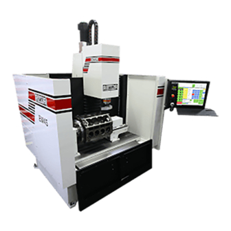
EM45 Installation Manual Description The model EM45 machine is a precision, single point boring, and high-speed surfacing unit. It can be equipped with tooling and accessories for surfacing and re-boring most small to medium gas and diesel engine blocks, both in-line and V-type. -
Page 6: Limited Warranty
This limited warranty remains in effect for one year from the date of installation or two years from the date of the original shipment from Rottler or whichever date occurs first. This only applies if the machine is owned and operated by the original purchaser and is operated and maintained as per the instructions in the manual. -
Page 7: Online Documentation Access
Online Documentation Access Online documentation for machines and optional equipment, including manuals and catalogs, can be accessed at the Rottler website. To access documentation, open your browser and navigate to https://www.rottlermfg.com Scroll to the bottom of the page and under the “Owner Resources” title, click the type of documentation you want to access. - Page 8 Section 1: Introduction EM45 Installation Manual 8029 S 200th Street, Kent, WA 98032 USA | www.rottlermfg.com | Ph: (253) 872-7050 | Fax: (253) 393-0230 Rev RD-010924...
- Page 9 Section 2: Installation EM45 Installation Manual INSTALLATION Contents Installation Preparation Requirements ..........2-2 Installation Report ..................2-4 Installation Procedure ................2-10 Machine Dimensions ..................2-11 Placement of Machine ................... 2-13 Location ......................2-13 Unpacking .....................2-13 Leveling ......................2-13 Re-Attaching the Control Screen ..............2-14 Air Supply.......................
-
Page 10: Installation Preparation Requirements
EM45 Installation Manual INSTALLATION CUSTOMER PREPARATION REQUIREMENTS 1. The floor needs to be prepared with anchor bolts installed. Rottler highly recommends the Hilti system. 2. Machine needs to be set in place with a leveling pad under each leveling bolt. After setting the machine in place, check that each anchor bolt nut turns freely and that there is no damage to the anchor bolt threads. - Page 11 Section 2: Installation EM45 Installation Manual ATTENTION OWNER/BUSINESS MANAGER To validate the warranty on your new Rottler machine, please complete and sign the installation report after the installation technician has installed the machine, verified the machine is operating correctly, and given the operator(s) operation and maintenance training.
-
Page 12: Installation Report
_______Customer has read and fully understands the importance of machine location as explained in the installation section of this manual. The following is the customer’s responsibility prior to the arrival of the Rottler technician. Please initial each item when it is completed. - Page 13 _______ Have an Internet connection available for the machine, either via ethernet cable or wireless. The machine comes with a USB Wireless adapter. The following is the Rottler technician’s responsibility _______ The electrical system is protected internally by circuit breakers. Verify that the breakers are set correctly.
- Page 14 Section 2: Installation EM45 Installation Manual MACHINE MOVEMENTS _______ Make sure there is nothing obstructing the full X-, Y-, and Z-Axis travel of the machine, taking special notice of the top of the column. _______ Put the machine in handwheel mode and verify Z-Axis operation. Raise the Z-Axis and remove the spindle support bracket.
- Page 15 INSTRUCTING THE OPERATOR Note: Rottler employees and representatives, per company policy, are not permitted to provide the end user of Rottler equipment with any OEM specifications for the workpiece that is created by the end user of Rottler equipment. _______ Explain to the customer and operator(s) that at NO time is there to be any software or hardware other than Windows Auto Update and Rottler Software installed on this machine.
- Page 16 _______ Explain offset tool bits, calibration of micrometers, and anvil setting _______ Train the operator(s) on ALL Rottler programs, even if they need to be run in the air. _______ If Rottler CAM was provided to the customer, train on any programs supplied by Rottler.
- Page 17 Rottler equipment. It is the responsibility of the end user of Rottler equipment to determine the final dimensions and finishes of the workpiece that they are working on. Any information regarding final dimensions and...
-
Page 18: Installation Procedure
ALWAYS rough level to be sure that the weight of the machine is evenly distributed over all the jacking bolts. Rottler recommends Hilti products with 3/4” (20mm) diameter X 12” (300mm) long studs at a minimum. It is the customer's responsibility to determine the appropriate anchors for local conditions. Drill floor approximately 7”... -
Page 19: Machine Dimensions
Section 2: Installation 2-11 EM45 Installation Manual Machine Dimensions Front View 8029 S 200th Street, Kent, WA 98032 USA | www.rottlermfg.com | Ph: (253) 872-7050 | Fax: (253) 393-0230 Rev RD-010924... - Page 20 Section 2: Installation 2-12 EM45 Installation Manual Top View 8029 S 200th Street, Kent, WA 98032 USA | www.rottlermfg.com | Ph: (253) 872-7050 | Fax: (253) 393-0230 Rev RD-010924...
-
Page 21: Placement Of Machine
The proper loading arrangement and area location for your EM45 machine is extremely important. A slow travel (6’ to 10’ per minute) power hoist, operated from either a bridge crane or a jib crane arrangement works very well. -
Page 22: Air Supply
Air Supply It is very important that the air source for the EM45 machine be moisture free. Water and oil in the line will result in early cylinder and valve failure. The factory recommends installing a water trap at the machine. -
Page 23: Power Supply
Section 2: Installation 2-15 EM45 Installation Manual Power Supply This machine has the following power requirements: • 208 to 240 VAC • Single or Three Phase • 50 or 60 Hertz 30 amps • See illustration below for correct connection of incoming power. Measured power at the machine’s main breaker must be within the required range listed above. -
Page 24: Grounding
Section 2: Installation 2-16 EM45 Installation Manual Grounding The machine requires a good earth ground. The grounding conductor from the incoming power source must be connected to the grounding block located inside of the electrical cabinet. A ground rod installed in addition to the electrical service grounding conductor is permitted but must be connected directly to the grounding block inside of the electrical cabinet. -
Page 25: Setting Soft Limits
X-Axis) CAUTION: Failure to do this can result in overtravel and damage. 3. From the main screen of the Rottler Block Software, select Setup Electronics Control. This will bring up the Control Options window. - Page 26 Section 2: Installation 2-18 EM45 Installation Manual 7. Set the Bottom Soft limit value according to this table: Axis EM45 8. Set the “Enable Top Soft Limit” and “Enable Bottom Soft Limit” back to “True” 9. Select Operations Set Home Preset to open a dialog window 10.
- Page 27 Section 2: Installation 2-19 EM45 Installation Manual 14. Set “Enable Top Secondary Soft Limit” and “Enable Bottom Secondary Soft Limit” to “True” 15. Set the Bottom limit to -17 and the Top limit to -2.5 16. Close all dialog boxes. Soft Limits are now fully set.
-
Page 28: Creating A Skype Account
Section 2: Installation 2-20 EM45 Installation Manual Creating a Skype Account Click on “Create an account” Click on “Use your email instead” Click on “Get new email address” 8029 S 200th Street, Kent, WA 98032 USA | www.rottlermfg.com | Ph: (253) 872-7050 | Fax: (253) 393-0230... - Page 29 Section 2: Installation 2-21 EM45 Installation Manual Name the email account using the Rottler machine Model and Serial number. Ex. H85A111, EM69P001 Create a password that is easy to remember. Uncheck the box to receive emails from Microsoft. First Name: Model-Serial Number Ex.
Need help?
Do you have a question about the EM45 and is the answer not in the manual?
Questions and answers