
Related Manuals for Rottler VR9


Summary of Contents for Rottler VR9
- Page 1 OPERATION AND MAINTENANCE MANUAL 8029 S 200th St Kent, WA 98032 USA | www.rottlermfg.com | Ph: 253-872-7050 | Fax: 253-395-0230 08.08.2019...
- Page 3 Contact your regional Rottler sales rep for assistance in ordering optional equipment, replacement parts, or tooling. If you are unable to contact your regional Rottler sales rep, call the factory at 253-872-7050 and ask to speak to the parts sales specialist.
- Page 5 “Installation Report” located in the Installation Chapter of this manual. We suggest that the new user of the VR9 read the CONTROL DEFINITIONS to get an idea how the machine operates. The Operating Instructions chapter should be read in order to familiarize the user with the actual button pushing sequences required to carry out a job.
- Page 6 Each Rottler Chuck offers a dual system of three hardened steel balls - one towards the front of the Chuck and another system in the back of the Chuck holding the valve in the portion of that will be running in the Guide to the valve stem.
- Page 7 The issuance of a RGR DOES NOT guarantee credit - it is only authorization for the return of the goods. Credit for return merchandise is at the sole discretion of Rottler. Credit will be issued only after inspection of returned goods.
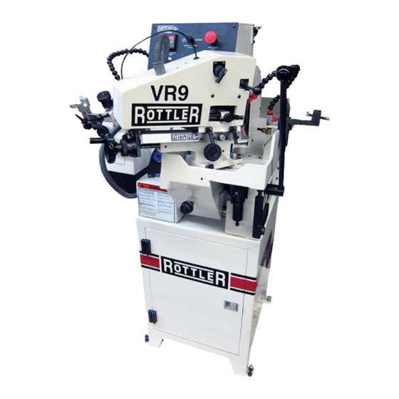
- Page 8 Section 1 Introduction VR9 Manual www.rottlermfg.com...
-
Page 9: Table Of Contents
Section 2 Installation VR9 Manual INSTALLATION Contents ROTTLER VR9 INSTALLATION REPORT ..............2-2 Installation Procedure ....................2-6 Unpacking and Lifting ......................2-6 Location ..........................2-6 Power Supply ........................2-7 Air Supply ..........................2-8 Adding Grinding Oil ......................2-9 www.rottlermfg.com... - Page 10 Section 2 Installation VR9 Manual ATTENTION OWNER/BUSINESS MANAGER To validate the warranty on your new Rottler machine, please be sure to sign the installation report after the installation technician has installed the machine and verified the machine is operating correctly and given the operators operation and maintenance training.
-
Page 11: Rottler Vr9 Installation Report
Make sure all electrical equipment has the proper overload protection. The VR9 should have a fully isolated power supply to prevent damage and uncontrolled movement of the machine. If the VR9 is on the same power lines that are running to other electrical equipment (grinders, welders, and other AC motors) electrical noise can be inducted into the VR9 electrical system. - Page 12 ______Point out safety features to customer and operator. Do not push any buttons without thinking of safety first. ______Check cooling pump and cooling tank for proper operation. ______Explain the importance of using only Rottler grinding oil. Use of non approved grinding oil will void the warranty.
- Page 13 Section 2 Installation VR9 Manual General remarks on machine performance, adjustments as received and any further organization or parts required to complete the set up: __________________________________________________________________________________________ __________________________________________________________________________________________ __________________________________________________________________________________________ __________________________________________________________________________________________ __________________________________________________________________________________________ __________________________________________________________________________________________ __________________________________________________________________________________________ __________________________________________________________________________________________ __________________________________________________________________________________________ __________________________________________________________________________________________ __________________________________________________________________________________________ __________________________________________________________________________________________ __________________________________________________________________________________________ Instructions given to: _________________________________________________________________________...
- Page 14 Section 2 Installation VR9 Manual www.rottlermfg.com...
-
Page 15: Installation Procedure
Section 2 Installation VR9 Manual Installation Procedure Unpacking and Lifting Use care when removing the crate materials from the machine. Be careful not to use force on any part of the machine. Remove the shipping screws (4) from the skid; the shipping brackets will be painted red and lifting bracket on yellow for easy identification. -
Page 16: Power Supply
Section 2 Installation VR9 Manual Power Supply General Warnings The electrical connection to the power source has to be done by electricians only. Verify if the feed line is in accordance with the norms in force. In the negative, keep the due remedy. Make sure the wiring connection to the power source has been correctly done and not hinder the normal operation and maintenance of the machine. -
Page 17: Air Supply
Section 2 Installation VR9 Manual Air Supply It is very important the air source for the VR9 machine be moisture free. Water and oil in the line will result in early cylinder and valve failure. The factory recommends installing a water trap at the machine. -
Page 18: Adding Grinding Oil
Section 2 Installation VR9 Manual Adding Grinding Oil Add grinding oil that was shipped with the machine by pouring oil into drainage area. www.rottlermfg.com... - Page 19 Section 3 Safety VR9 Manual SAFETY Contents Safety Information .......................3-1 Safety Instructions for Machine Use .................3-1 Electrical Power ......................3-3 Machine Operator ......................... 3-4 Emergency Procedure ......................3-4 When Using the VR9 Machine ..................... 3-5 www.rottlermfg.com...
-
Page 20: Safety Information
Section 3 Safety VR9 Manual Safety Information For Your Own Safety Read This Instruction Manual Before Operating This Machine. This is the safety alert symbol. It is used to alert you to potential personal injury hazards. Obey all safety messages that follow this symbol to avoid possible injury or death. - Page 21 DO NOT MODIFY OR ALTER THIS EQUIPMENT in any way. If modifications are deemed necessary, all such requests must be approved and/or handled by Rottler Manufacturing. Unauthorized modifications could cause injury and/or damage to machine and will void the warranty.
-
Page 22: Electrical Power
If the VR9 is on the same power lines that are running to other electrical equipment (grinders, welders, and other AC motors) electrical noise can be induced into the VR9 electrical system. -
Page 23: Machine Operator
The VR9 machines have the following areas of exposed moving parts that you must train yourself to respect and stay away from when they are in motion: Cutting Tool Area –... -
Page 24: When Using The Vr9 Machine
Section 3 Safety VR9 Manual When Using the VR9 Machine • Never use wheels, which that have been dropped or damaged • Never use excessive pressure when installing a new wheel between the wheel and hubs. Tighten nut only enough to hold wheel firmly. - Page 25 Section 4 Control Definitions VR9 Manual CONTROL DEFINITIONS AND SWITCHES Before attempting to operate this machine, first familiarize yourself with all controls and switches and the functions of each component of the machine. Stop Switch By pressing, the Stop Switch will turn any function off the machine and for emergency purpose.
- Page 26 Section 4 Control Definitions VR9 Manual www.rottlermfg.com...
- Page 27 Section 5 Operating Instructions VR9 Manual OPERATING INSTRUCTIONS Contents Operating Instructions ....................5-1 Machine Operator ......................... 5-2 Work Area ............................5-2 Overreach ............................5-2 Hand Safety ............................5-2 Machine Capacity ......................... 5-2 Avoid Accidental Starting.........................5-2 Careless Acts ............................5-2 Job Completion ..........................5-2 Replacement Parts ..........................5-2 Misuse ..............................5-2...
-
Page 28: Operating Instructions
Section 5 Operating Instructions VR9 Manual Operating Instructions The ROTTLER VR9 MODEL is a machine fitted with high speed rotating grinding wheels, it is therefore very important to apply the following safety instructions. Do not use the machine without all the guards on. -
Page 29: Machine Operator
VR9 Manual Machine Operator The operator of the VR9 should be a skilled machinist craftsman who is well versed in the caution, care, and knowledge required to safely operate metal cutting tools. Clean the machine carefully, removing the protective grease spread on unpainted parts. -
Page 30: Emergency Procedure
PRESS THE EMERGENCY STOP BUTTON (on the front control panel) IMMEDIATELY! Grinding Wheel Use ONLY the ROTTLER grinding wheels using the reference numbers listed on consumable section of this manual. Those grinding wheels are already balanced before delivery. Attention! The use of original parts is required. - Page 31 Section 5 Operating Instructions VR9 Manual www.rottlermfg.com...
-
Page 32: Main Valve Grinding Wheel Removal
Section 5 Operating Instructions VR9 Manual Main Valve Grinding Wheel Removal 1. Remove the three mounting screws holding the wheel guard in place. 2. Push the locking pin in to lock the spindle from turning and remove the wheel retaining bolt 3. -
Page 33: Dressing The Main Grinding Wheel
VR9 Manual Dressing the Main Grinding Wheel Use ONLY the ROTTLER grinding wheels using the reference numbers listed on consumable section of this manual. Those grinding wheels are already balanced before delivery. Attention! The use of original parts is required. -
Page 34: Dressing The Butt Wheel
Section 5 Operating Instructions VR9 Manual Dressing the Butt Wheel The Valve stem grinding wheel needs to be dressed periodically, to keep a sharp cutting edge and a clean face. Note: NEVER MAKE THE WHEEL ROTATE WITHOUT ITS PROTECTING COVER Install dressing diamond in place as shown below. -
Page 35: Operating Guide
Section 5 Operating Instructions VR9 Manual Operating Guide The ROTTLER VR9 MODEL is a machine fitted with high speed rotating grinding wheels, it is therefore very important to apply the following safety instructions. Do not use the machine without all the guards on. -
Page 36: Calibrating The Digital Angle Display
Section 5 Operating Instructions VR9 Manual Calibrating the Digital Angle Display 1. Set the rocker arm so that the scale is at zero by losing the swing angle position block and then clamped. Referred to (Fig. 1) 2. Fit the calibrating device (Fig. 2) into the chuck the same as if a valve is to be ground. -
Page 37: Resurfacing Procedure
Section 5 Operating Instructions 5-10 VR9 Manual Resurfacing Procedure Note: To achieve a good run out on the valve head is imported to keep valve stem clean and the butt must be resurface. www.rottlermfg.com... -
Page 38: Grinding Of Valve
Section 5 Operating Instructions 5-11 VR9 Manual Grinding of Valve 1. Grinding angle setting 2. Check the valve seat angle that you will be grinding. a. Loosen the handle or locking nut A and rotate the slide support valve holding group look at the angle pointer J and set it to the angle from the valve. -
Page 39: Stem Ends
Section 5 Operating Instructions 5-12 VR9 Manual Stem Ends 1- Install the valve stem on the clamping block axis, on the right side of the machine, with the straight "V" near the wheel. To do that, you have to lock the index in position B, and rotate the clamping block by using the lever handle F. -
Page 40: Valve Stem Chamfering
Section 5 Operating Instructions 5-13 VR9 Manual Valve Stem Chamfering 1. Put the end stop knob A on the valve and block it in position (not too tight). 2. Use the "V" 45° to the wheel to clamp the valve onto the clamping block. Use... - Page 41 Section 6 Maintenance VR9 Manual MAINTENANCE Contents Maintenance .........................6-1 Lubricating the Chuck Slideways ..................6-1 Cleaning Drive Rollers ......................6-1 Adjusting Gibs of Chuck Slideway ..................6-2 BALL CHUCK ........................6-3 Maintenance Procedure for VR Ball Chucks ..............6-3 Replacing Spindle Bearings ....................6-7 SUGGESTED TIPS ........................
-
Page 42: Maintenance
Section 6 Maintenance VR9 Manual Maintenance The Rottler VR9 has been designed to be a low maintenance machine. However, some basic maintenance will ensure long life and accurate results. Lubricating the Chuck Slideways Lubrication –The slideways must be lubricated with ISO VG 68 Way Oil before starting a new machine and weekly during use of the machine. -
Page 43: Adjusting Gibs Of Chuck Slideway
Section 6 Maintenance VR9 Manual Adjusting Gibs of Chuck Slideway After transport and use, the gibs of the chuck slideways may become lose and require some adjusting. Be sure that the gibs are well oiled as described in lubrication chapter before attempting to tighten the gibs. It is best to tighten the gib set screws without loosening the locknuts. -
Page 44: Ball Chuck
Squirt ATF fluid into the inside of the ball chuck. Be certain to squirt on each of the 6 balls to flush out any debris and ensure proper lubrication. Contact the Service Department using the service form on the Rottler web site if further assistance is required... - Page 45 Section 6 Maintenance VR9 Manual www.rottlermfg.com...
- Page 46 Section 6 Maintenance VR9 Manual www.rottlermfg.com...
- Page 47 Section 6 Maintenance VR9 Manual www.rottlermfg.com...
-
Page 48: Replacing Spindle Bearings
Section 6 Maintenance VR9 Manual Replacing Spindle Bearings www.rottlermfg.com... -
Page 50: Suggested Tips
VR9 Manual SUGGESTED TIPS Familiarize yourself with your Rottler VR9 valve grinding machine. We recommend that before you start grinding on customer valves, use waste valves to practices. This will prevent any undue pressure or errors while learning on a customer valves. - Page 51 Section 7 Troubleshooting VR9 Manual TROUBLESHOOTING Contents Troubleshooting ......................7-1 Pneumatic Circuit Diagram ....................7-1 Control Circuit Diagram ....................... 7-2 Power Circuit Diagram ......................7-3 www.rottlermfg.com...
-
Page 52: Troubleshooting
Section 7 Troubleshooting VR9 Manual Troubleshooting Valve will not auto feed or Oil on drive rollers Clean drive rollers, see instructions in release properly Maintenance section Pneumatic Circuit Diagram www.rottlermfg.com... -
Page 53: Control Circuit Diagram
Section 7 Troubleshooting VR9 Manual Control Circuit Diagram www.rottlermfg.com... -
Page 54: Power Circuit Diagram
Section 7 Troubleshooting VR9 Manual Power Circuit Diagram www.rottlermfg.com... - Page 55 Section 8 Machine Parts VR9 Manual MACHINE PARTS Contents Consumable Parts for VR9 ..................8-1 Machine Parts ......................8-2 Control Circuit Diagram ....................... 8-2 Power Circuit Diagram ......................8-3 Pneumatic Circuit Diagram ....................8-4 Machine Parts ......................8-5 Base Assembly ........................8-5 Base Assembly Parts List ........................8-6 Grinding Wheel Assembly ....................
-
Page 56: Consumable Parts For Vr9
Section 8 Machine Parts VR9 Manual Consumable Parts for VR9 Part Number Description VTRW-10 Main Grinding Wheel 9.0" (200mm) Diameter General Purpose VTRW-11 Main Grinding Wheel 9.0" (200mm) Diameter Special Applications, Titanium VTRW-12 Main Grinding Wheel 9.0" (200mm) Diameter Special Applications, Stellite... -
Page 57: Machine Parts
Section 8 Machine Parts VR9 Manual Machine Parts Control Circuit Diagram www.rottlermfg.com... -
Page 58: Power Circuit Diagram
Section 8 Machine Parts VR9 Manual Power Circuit Diagram www.rottlermfg.com... -
Page 59: Pneumatic Circuit Diagram
Section 8 Machine Parts VR9 Manual Pneumatic Circuit Diagram www.rottlermfg.com... -
Page 60: Machine Parts
Section 8 Machine Parts VR9 Manual Machine Parts Base Assembly www.rottlermfg.com... -
Page 61: Base Assembly Parts List
Section 8 Machine Parts VR9 Manual Base Assembly Parts List www.rottlermfg.com... - Page 62 Section 8 Machine Parts VR9 Manual www.rottlermfg.com...
-
Page 63: Grinding Wheel Assembly
Section 8 Machine Parts VR9 Manual Grinding Wheel Assembly www.rottlermfg.com... -
Page 64: Grinding Wheel Assembly Parts List
Section 8 Machine Parts VR9 Manual Grinding Wheel Assembly Parts List www.rottlermfg.com... -
Page 65: Slide Support Assembly
Section 8 Machine Parts 8-10 VR9 Manual Slide Support Assembly www.rottlermfg.com... -
Page 66: Slide Support Assembly Parts List
Section 8 Machine Parts 8-11 VR9 Manual Slide Support Assembly Parts List www.rottlermfg.com... -
Page 67: Power Head Assembly
Section 8 Machine Parts 8-12 VR9 Manual Power Head Assembly www.rottlermfg.com... -
Page 68: Power Head Assembly Parts List
Section 8 Machine Parts 8-13 VR9 Manual Power Head Assembly Parts List www.rottlermfg.com... -
Page 69: Control Panel Assembly
Section 8 Machine Parts 8-14 VR9 Manual Control Panel Assembly www.rottlermfg.com... -
Page 70: Control Panel Assembly Parts List
Section 8 Machine Parts 8-15 VR9 Manual Control Panel Assembly Parts List www.rottlermfg.com... -
Page 71: Rocker Feed Assembly
Section 8 Machine Parts 8-16 VR9 Manual Rocker Feed Assembly www.rottlermfg.com... -
Page 72: Rocker Feed Assembly Parts List
Section 8 Machine Parts 8-17 VR9 Manual Rocker Feed Assembly Parts List www.rottlermfg.com... - Page 73 Section 8 Machine Parts 8-18 VR9 Manual Spindle Assy Parts www.rottlermfg.com...
- Page 74 Section 8 Machine Parts 8-19 VR9 Manual Spindle Assy Parts List www.rottlermfg.com...
- Page 75 VTRW-10 Main Grinding Wheel General Purpose ................9-4 VTRW-3 Butt Grinding Wheel .........................9-4 Parts and Supplies ......................9-5 7609C Grinding Oil 5 Gallon (20 Liters) ....................9-5 514-7-66F Filter Paper ..........................9-5 514-4-71D Coolant Refractor ........................9-5 VR9-TOPROLL Top Roller for VR9 ......................9-5 VR9-ROLLER Complete roller set for VR9 ....................9-5 www.rottlermfg.com...
-
Page 76: Valve Measuring Equipment
Section 9 Options VR9 Manual Valve Measuring Equipment VALVE-CHECK Valve Stem Runout Fixture Assembly measures Valve Seat and Valve Stem Runout with two separate dial gages, specify Inch .0001” or Metric .002mm www.rottlermfg.com... -
Page 77: Steady-Rest Vr9
Section 9 Options VR9 Manual STEADY-REST VR9 Steady rest for grinding titanium valves www.rottlermfg.com... -
Page 78: Grinding Wheels And Diamond Dressers
Section 9 Options VR9 Manual Grinding Wheels and Diamond Dressers Vitrified Grinding Wheels, require Grinding Oil 7609B VTRW-11 Main Grinding Wheel Special Applications, Titanium 9.0” (230mm) Diameter (Green) VTRW-12 Main Grinding Wheel Special Applications, Hard Valves 9.0” (228.6mm) Diameter (Pink) -
Page 79: Vtrw-10 Main Grinding Wheel General Purpose
Section 9 Options VR9 Manual VTRW-10 Main Grinding Wheel General Purpose 9.0” (230mm) Diameter VTRW-3 Butt Grinding Wheel General Purpose www.rottlermfg.com... -
Page 80: Parts And Supplies
514-7-66F Filter Paper Minimum order of (10) sheets, pricing per sheet 514-4-71D Coolant Refractor (for measuring coolant/water ratio) VR9-TOPROLL Top Roller for VR9 VR9-ROLLER Complete roller set for VR9 (includes top roller and bottom drive rollers, shafts, bearings and gears) www.rottlermfg.com... - Page 81 A complete list of the Material Data Safety Sheets of substances and materials used by Rottler Manufacturing during manufacturing, testing, and shipping is located on the Manual CD shipped with the machine. Material Data Safety Sheets are also located on the company web site: http://www.rottlermfg.com/documentation.php...
- Page 82 Section 10 Material Data Safety Sheets 10-2 VR9 Manual SAFETY DATA SHEET Section 1. Identification Product name Honilo 710 SDS # 461349 Historic SDS #: 05267 Code 461349-US03 Relevant identified uses of the substance or mixture and uses advised against Product use Metalworking fluid - neat.
- Page 83 Section 10 Material Data Safety Sheets 10-3 VR9 Manual Section 3. Composition/information on ingredients Cooling agents for metal processing - Honing oils Substance/mixture Mixture Ingredient name CAS number Distillates, petroleum, hydrotreated middle 64742-46-7 85-90 Any concentration shown as a range is to protect confidentiality or is due to batch variation.
- Page 84 Section 10 Material Data Safety Sheets 10-4 VR9 Manual Section 5. Fire-fighting measures Special protective actions Promptly isolate the scene by removing all persons from the vicinity of the incident if there is a fire. No action shall be taken involving any personal risk or without suitable for fire-fighters training.
- Page 85 Section 10 Material Data Safety Sheets 10-5 VR9 Manual Section 7. Handling and storage Conditions for safe storage, Store in accordance with local regulations. Store in original container protected from direct sunlight in a dry, cool and well-ventilated area, away from incompatible materials including any (see Section 10) and food and drink.
- Page 86 Section 10 Material Data Safety Sheets 10-6 VR9 Manual Section 8. Exposure controls/personal protection Body protection Use of protective clothing is good industrial practice. Cotton or polyester/cotton overalls will only provide protection against light superficial contamination that will not soak through to the skin.
- Page 87 Section 10 Material Data Safety Sheets 10-7 VR9 Manual Section 10. Stability and reactivity Incompatible materials Reactive or incompatible with the following materials: oxidizing materials. Hazardous decomposition Under normal conditions of storage and use, hazardous decomposition products should not be produced.
- Page 88 Section 10 Material Data Safety Sheets 10-8 VR9 Manual Section 11. Toxicological information Section 12. Ecological information Toxicity No testing has been performed by the manufacturer. Persistence and degradability Expected to be biodegradable. Bioaccumulative potential Not available. Mobility in soil Soil/water partition Not available.
- Page 89 Section 10 Material Data Safety Sheets 10-9 VR9 Manual Section 14. Transport information Transport in bulk according Not available. to Annex II of MARPOL 73/78 and the IBC Code Section 15. Regulatory information U.S. Federal regulations United States inventory All components are listed or exempted.
- Page 90 Section 10 Material Data Safety Sheets 10-10 VR9 Manual Section 16. Other information Flammability Health Instability/Reactivity Special History 08/11/2014. Date of issue/Date of revision Date of previous issue No previous validation. Key to abbreviations ACGIH = American Conference of Industrial Hygienists...
Need help?
Do you have a question about the VR9 and is the answer not in the manual?
Questions and answers