Table of Contents
Advertisement
MANUFACTURING
SEAT AND GUIDE MACHINE
OPERATIONS AND MAINTENANCE
MANUFACTURED BY:
ROTTLER MANUFACTURING COMPANY
8029 South 200th Street
Kent Washington 98032 USA
Phone:
Fax:
NOTE: WHEN ORDERING REPLACEMENT PARTS,
PLEASE GIVE THE MODEL AND SERIAL NUMBER.
ORDER BY PART NUMBER.
THERE IS A MINIMUM ORDER OF $25.00
SG8
MANUAL
(253) 872-7050
(253) 395-0230
August 8, 2019
Advertisement
Table of Contents

Related Manuals for Rottler SG8


Summary of Contents for Rottler SG8
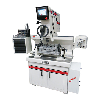
- Page 1 August 8, 2019 MANUFACTURING SEAT AND GUIDE MACHINE OPERATIONS AND MAINTENANCE MANUAL MANUFACTURED BY: ROTTLER MANUFACTURING COMPANY 8029 South 200th Street Kent Washington 98032 USA Phone: (253) 872-7050 Fax: (253) 395-0230 NOTE: WHEN ORDERING REPLACEMENT PARTS, PLEASE GIVE THE MODEL AND SERIAL NUMBER.
-
Page 2: Table Of Contents
CHAPTER 1 INTRODUCTION / SAFETY / INSTALLATION: 2-1 Introduction:..............................2-1 Limited Warranty: ............................2-1 Safety Information: .............................2-2 Electrical Power:............................2-2 Machine Operator:............................2-2 Eye Safety: ..............................2-2 Work Area: ..............................2-2 Guards:...............................2-2 Overreach:..............................2-2 Hand Safety:...............................2-2 Machine Capacity:............................2-3 Avoid Accidental Starting: ..........................2-3 Careless Acts: ............................2-3 Job Completion: ............................2-3 Replacement Parts:............................2-3 Misuse: ...............................2-3 Emergency Procedure:..........................2-3... - Page 3 Calibrating the Digital Level: ........................7-1 The New Chip collector System: ........................7-1 CHAPTER 7 TROUBLESHOOTING: Eccentricity Problems when Cutting Three Angle Seats:................8-1 CHAPTER 8 WIRING DIAGRAM 9-1 Wiring Diagram............................9-1 CHAPTER 9 PNEUMATIC DRAWINGS 10-1 CHAPTER 10 MACHINE PARTS 11-1 Base, Table and Riser Assembly ......................11-1 WORKHEAD ASSEMBLY........................11-3 SPINDLE ASSEMBLY..........................11-1 TRANSMISSION ASSEMBLY .........................11-4...
- Page 4 53” UPPER SURFACES OVERALL HEIGHT 83" AIR REQUIREMENT 100 P.S.I. Note: Rottler reserves the rights to change any specifications FLOOR SPACE 33" deep x 93" wide and over all product design out any notice. REQUIREMENTS with tool box and sharpener SHIPPING WEIGHT 2600 lbs.
-
Page 5: Chapter 1 Introduction / Safety / Installation
Chapter 2 Introduction / Safety / Installation: Introduction: This manual is divided into sections as listed in the table of contents. It is required that the new user of the SG8 read this manual, in particular the sections concerning safety, before operating the machine. Limited Warranty: Rottler Manufacturing Company Model SG8 parts and equipment is warranted as to materials and workmanship. -
Page 6: Safety Information
This machine is capable of causing severe bodily injury or death if EXTREME care is not used when operating! The operator of the SG8 should be a skilled machinist craftsman who is well versed in the caution, care, and knowledge required to safely operate metal cutting tools. -
Page 7: Machine Capacity
Use only Rottler replacement parts and accessories; otherwise, warranty will be null and void. Misuse: Do not use the machine for other than its intended use. If used for other purposes, Rottler Manufacturing disclaims any real or implied warranty and holds itself harmless for any injury or loss that may result from such use. -
Page 8: Chapter 2 Machine Installation
The proper loading arrangement and location for your SG8 machine is extremely important. A slow travel (6 to 10 feet / min.) power hoist operated from either a bridge crane or a jib crane arrangement works very well. -
Page 9: Leveling The Machine
Operating Instructions SG8 Manual Leveling the Machine: Before leveling the machine, loosen and remove the shipping brackets securing the air float Workhead. (Figures 1 & 2). The air float clamp plate bolts may need to be loosened also. Access to these bolts is gained by tilting the spindle assembly to the left and loosening the bolts on that side approximately 1 turn. -
Page 10: Chapter 3 Control Definitions
Operating Instructions SG8 Manual Chapter 4 Control Definitions: SGF8 Control Definitions DIGITAL LEVEL READOUT SPINDLE RPM READOUT LAMP SWITCH RPM DECREASE SWITCH RPM INCREASE SWITCH SPINDLE START SWITCH SPINDLE DIRECTION SPINDLE TILT HANDWHEEL POWER OFF SWITCH SPINDLE TILT LOCK DIAL DEPTH INDICATOR... -
Page 11: Chapter 4 Operating Instructions
Operating Instructions SG8 Manual Chapter 5 Operating Instructions: Mounting Cylinder Heads: Initial clamp height adjustments to the head trunions can be accomplished by measuring the head thickness then raising the turning clamping block assembly to the appropriate height using the clamping block acme screws. -
Page 12: Alignment And Setup
The Rottler-Klamp head mounting fixture is provided to accommodate cylinder heads that are difficult to mount directly into the trunions. Some machine operators prefer to use the Rottler-Klamp fixture for the majority of heads as the mounting is very quick. The Rottler-Klamp frame is mounted between the trunions and clamped using the clamping plates. -
Page 13: Selecting The Right Pilot
Once that you have the toolholder setup, fit the ball head toolholder into the spring free spindle adapter. The SG8 spindle was engineered to allow ultra fast tooling changes .Make sure the that spindle spring free locking nut is in the off lock position, line up the two ears of the spindle adapter and insert into the spindle ISO 30 taper, the locking nut automatically will be on the lock position, to remove turn the self locking nut to the left position, hold the spindle adapter, it may drop on the machine table. -
Page 14: Chapter 5 Spindle To Work
Operating Instructions SG8 Manual Chapter 6 Spindle to Work: When the cylinder head is clamped properly on the table and adjusted, move the workhead to the first valve guide by pushing on the food pedal. At this point the spindle and workhead should be level according to the position of the cylinder head. -
Page 15: Cutting Counter Bores For Seat Rings
Operating Instructions SG8 Manual Cutting Counter Bores for Seat Rings: Align the work piece as explained previously. Cylinder head deck surface must be up. Insert correct pilot into the valve guide. Mount the correct milling head cutter on the milling head Adapter, Install milling head adapter into spindle adapter... -
Page 16: Chapter 6 Maintenance
Operating Instructions SG8 Manual Chapter 7 Maintenance: Calibrating the Digital Level: NOTE: Even though the level has been carefully calibrated at the factory, it is a good idea to recheck calibration before putting the machine into service. In the event that the level is dropped or handled... -
Page 17: Chapter 7 Troubleshooting
Troubleshooting SG8 Manual Chapter 8 Troubleshooting: Eccentricity Problems when Cutting Three Angle Seats: Spindle floated to improper center location. Excessive pressure when machining the seat. Incorrect spindle speed. Worn or improperly selected pilot. Worn Valve Guide. -
Page 18: Chapter 8 Wiring Diagram
Machine Parts SG8 Manual Chapter 9 Wiring Diagram Wiring Diagram... -
Page 19: Chapter 9 Pneumatic Drawings
Machine Parts 10-1 SG8 Manual Chapter 10 Pneumatic Drawings... -
Page 20: Chapter 10 Machine Parts
Machine Parts 11-1 SG8 Manual Chapter 11 Machine Parts Base, Table and Riser Assembly CUTTING EDGE BASE, TABLE AND RISER ASSEMBLY PLATE NO. -1 SGF-8... - Page 21 Machine Parts 11-2 SG8 Manual BASE TABLE & RISER ASSEMBLY PLATE NO. – 1 S. NO. DESCRIPTION QTY/M/C COVER PAN RISER SCREW WASHER STOP PLATE PLATE VACCUM GAUGE 2.5” STD-B X ¼ NPT N-22-SW (9301) SV-3-M5 (6817) GSS-6 (153158) TOOL CABINET...
-
Page 22: Workhead Assembly
Machine Parts 11-3 SG8 Manual WORKHEAD ASSEMBLY CUTTING EDGE BASE ASSEM BLY 28,29 SPIN DLE HOUSIN G PLATE NO. - 2 SGF- 8... - Page 23 Machine Parts 11-4 SG8 Manual WORKHEAD ASSEMBLY PLATE NO. - 2 S. NO. DESCRIPTION QTY/M/C BASE SET SCREW 5/16” NF X 3/8” PLUG (BRASS) 555-14-29 BALL BEARING 555-14-30 WASHER OD 0.350”, ID 0.203” X 0.05” THK 555-14-31 ECCENTRIC PIN 555-14-32...
- Page 24 Machine Parts 11-5 SG8 Manual SET SCREW 5/16” BSW X ¼” F.PT. S. NO. DESCRIPTION QTY/M/C HANDLE ALLEN HD SCREW 5/16” BSW X 2.50’ NYLOCK NUT 3/8” UNF EYE BOLT ECCENTRIC COLLAR LEVER KNOB PIVOT PIN ECCENTRIC COLLAR TAPER PIN RING ALLEN HEAD SCR.
-
Page 25: Spindle Assembly
Machine Parts 11-1 SG8 Manual SPINDLE ASSEMBLY CUTTING EDGE SPINDLE ASSEMBLY CURRENT 10,11,12 45 46 26,27 LATEST SGF-8 PLATE NO. - 3... - Page 26 Machine Parts 11-2 SG8 Manual SPINDLE ASSEMBLY PLATE NO. - 3 S. NO. DESCRIPTION QTY/M/C DRIVE SHAFT RUBBER SEAL QUICK NUT SPRING TAPER ROLLER BEARING COLUMN BALL BEARING PLATE BRASS PAD C.PT. GRUB SCR. 3/16” X 1/2” BSW F.PT GRUB SCR. 3/16” X 1/2” BSW...
- Page 27 Machine Parts 11-3 SG8 Manual SPINDLE ASSEMBLY PLATE NO. - 3 S. NO. DESCRIPTION QTY/M/C WASHER C’SINK SCR.1/4” X 1/2” BSW M4-BALL PLUNGER SCREW INDICATOR MTG. FLAT INDICATOR MTG. ROD DIAL CLAMP INDICATOR KNOB LEVELING PIN PLATE (LEVELING PIN) CONTROL PANEL MOUNTING...
-
Page 28: Transmission Assembly
Machine Parts 11-4 SG8 Manual TRANSMISSION ASSEMBLY CUTTING EDGE TRANSMISSON ASSEMBLY PLATE NO. - 4 SGF-8... - Page 29 Machine Parts 11-5 SG8 Manual TRANSMISSION ASSEMBLY PLATE NO. - 4 S. NO. DESCRIPTION QTY/M/C SENSOR WHEEL EXT. CIRCLIP BALL BEARING ALLEN SCR. ¼” BSW X ¾” BEARING HOUSING PLATE ALLEN SCREW 10-32 X 5/8” LONG DRIVE PULLEY FLANGE IDLER PULLEY ALLEN SCREW ¼”...
-
Page 30: Head Support Assembly
Machine Parts 11-6 SG8 Manual HEAD SUPPORT ASSEMBLY CUTTING EDGE HEAD SUPPORT ASSEMBLY PLATE NO. - 5 SGF-8... - Page 31 Machine Parts 11-7 SG8 Manual HEAD SUPPORT ASSEMBLY PLATE NO. - 5 S. NO. DESCRIPTION QTY/M/C HEAD SUPPORT LEFT WASHER CLAMP BOLT 2 EACH HOLDER LEFT BUSH SCREW SCREW GRUB SCREW SCREW BEARING BUSH LEFT PLATE C’SINK SCREW KNURLING COLLAR SCREW 1/4"-20...
- Page 32 Machine Parts 11-8 SG8 Manual HEAD SUPPORT ASSEMBLY PLATE NO. - 5 S. NO. DESCRIPTION QTY/M/C TUBE KNOB TAKE UP ROD...
-
Page 33: Chapter 11 Fixed Carbide Pilots On Stock
Options 12-1 SG8 Manual Chapter 12 Fixed Carbide Pilots On Stock Part Number Description FCPM0399 3.99mm .1570" Fixed Carbide Pilot with 6.00mm Shank Diameter FCPM0400 4.00mm .1575" Fixed Carbide Pilot with 6.00mm Shank Diameter FCPM0449 4.49mm .1768" Fixed Carbide Pilot with 6.00mm Shank Diameter FCPM0450 4.50mm .1772"... -
Page 34: 375" Shank Diameter Fixed Carbide Pilots
Options 12-1 SG8 Manual 375" Shank Diameter Fixed Carbide Pilots FCP0500 5.00mm .1968" Fixed Carbide Pilot .375" (9.52mm) Shank Dia FCP0544 5.44mm .2141" Fixed Carbide Pilot .375" (9.52mm) Shank Dia FCP0547 5.47mm .2153" Fixed Carbide Pilot .375" (9.52mm) Shank Dia FCP0548 5.48mm .2157"... - Page 35 Options 12-2 SG8 Manual FCP0789 7.89mm .3106" Fixed Carbide Pilot .375" (9.52mm) Shank Dia FCP0790 7.90mm .3110" Fixed Carbide Pilot .375" (9.52mm) Shank Dia FCP0791 7.91mm .3114" Fixed Carbide Pilot .375" (9.52mm) Shank Dia FCP0792 7.92mm .3118" Fixed Carbide Pilot .375" (9.52mm) Shank Dia FCP0793 7.93mm .3122"...
- Page 36 Options 12-3 SG8 Manual FCP0876 8.76mm .3449" Fixed Carbide Pilot .375" (9.52mm) Shank Dia FCP0892 8.92mm .3512" Fixed Carbide Pilot .375" (9.52mm) Shank Dia FCP0894 8.94mm .3519" Fixed Carbide Pilot .375" (9.52mm) Shank Dia FCP0895 8.95mm .3523" Fixed Carbide Pilot .375" (9.52mm) Shank Dia FCP0896 8.96mm .3527"...
- Page 37 Options 12-4 SG8 Manual FCP0978 9.78mm .3850" Fixed Carbide Pilot .375" (9.52mm) Shank Dia FCP0979 9.79mm .3854" Fixed Carbide Pilot .375" (9.52mm) Shank Dia FCP0980 9.80mm .3858" Fixed Carbide Pilot .375" (9.52mm) Shank Dia FCP0983 9.83mm .3870" Fixed Carbide Pilot .375" (9.52mm) Shank Dia FCP0984 9.84mm .3874"...
- Page 38 Options 12-5 SG8 Manual FCP1149 11.49mm .4524" Fixed Carbide Pilot .375" (9.52mm) Shank Dia FCP1150 11.50mm .4528" Fixed Carbide Pilot .375" (9.52mm) Shank Dia FCP1151 11.51mm .4531" Fixed Carbide Pilot .375" (9.52mm) Shank Dia FCP1168 11.68mm .4598" Fixed Carbide Pilot .375" (9.52mm) Shank Dia FCP1198 11.98mm .4717"...
-
Page 39: Chapter 12 Seat And Guide Carbide Inserts
Options 13-6 SG8 Manual Chapter 13 Seat and Guide Carbide Inserts: Carbide Profile Tips: Replacement carbide tips for forming valve seats are individually specified by: Seat angle & seat width, top angle & top width, and throat angle. Identify the proper tip for your application. - Page 40 Options 13-7 SG8 Manual RCA 035 Carbide Seat Insert 25-45-60 / 1.4 -1.0 RCA 036 Carbide Seat Insert 25-45-60 / 1.8 -1.0 RCA 037 Carbide Seat Insert 35-45-52 / 1.6 -1.0 RCA 038 Carbide Seat Insert 35-45-55 / 1.6 -1.0...
- Page 41 Options 13-8 SG8 Manual RCA 325 Carbide Seat Insert 20-30-60 / 3.0 -1.5 RCA 326 Carbide Seat Insert 15-30-60 / 1.4 -2.0 RCA 327 Carbide Seat Insert 15-30-60 / 1.8 -2.0 RCA 328 Carbide Seat Insert 15-30-60 / 1.8 -2.5...
- Page 42 Options 13-9 SG8 Manual RCA 613 Carbide Seat Insert R2-30-45-60-R7 / 1.9-0.8 RCA 614 Carbide Seat Insert R4 -15 / 5.52 mm RCA 615 Carbide Seat Insert R4 -30 / 5.70 mm RCA 616 Carbide Seat Insert R5 -15 / 5.00 mm...
Need help?
Do you have a question about the SG8 and is the answer not in the manual?
Questions and answers