Table of Contents
Advertisement
Quick Links
Advertisement
Chapters
Table of Contents

Related Manuals for Rottler HP 7A


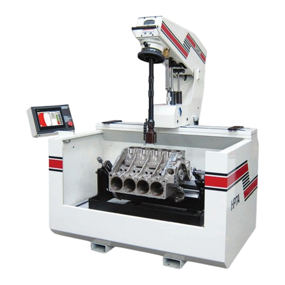
Summary of Contents for Rottler HP 7A
- Page 1 27.08.2015...
- Page 3 Contact your regional Rottler sales rep for assistance in ordering optional equipment, replacement parts, or tooling. If you are unable to contact your regional Rottler sales rep, call the factory at 253-872-7050 and ask to speak to the parts sales specialist.
- Page 5 READ THE SAFETY CHAPTER BEFORE INSTALLING MACHINE. THOROUGHLY UNDERSTAND ALL SAFETY ISSUES BEFORE OPERATING MACHINE. ATTENTION OWNER/BUSINESS MANAGER To validate the warranty on your new Rottler machine, please be sure to sign and complete the “Installation Report” located in the Installation Chapter of this manual.
- Page 6 Should a product not be as warranted, Rottler sole obligation shall be, at its option, to repair, correct or replace the product or to refund the amounts paid for the Product upon its return to a location designated by Rottler.
- Page 7 Rottler. Rottler shall not be liable for any consequential, direct or indirect damages or for any other injury or loss. Buyer waives any right, beyond the foregoing warranty, to make a claim against Rottler.
- Page 8 Section 1 Introduction HP7A Manual www.rottlermfg.com...
-
Page 9: Table Of Contents
Section 2 Installation HP7A Manual INSTALLATION Contents ROTTLER HP7A INSTALLATION REPORT ..............2-2 Installation Procedure ....................2-6 Location ..........................2-6 Unpacking ..........................2-6 Leveling ..........................2-6 Air Supply ..........................2-6 Coolant ..........................2-6 Power Supply ........................2-7 Grounding ............................2-7 Single Phase Electrical Hook-Up ..................2-8... - Page 10 Section 2 Installation HP7A Manual ATTENTION OWNER/BUSINESS MANAGER To validate the warranty on your new Rottler machine, please be sure to sign the installation report after the installation technician has installed the machine and verified the machine is operating correctly and given the operators operation and maintenance training.
-
Page 11: Rottler Hp7A Installation Report
Representative:________________________ MACHINE INSTALLATION: Electrical information MUST be complete to validate this report. Customer responsibility prior to the arrival of Rottler Sales/Service technician. Please Initial each item when it is completed. VERY IMPORTANT: Modern design machines contain electronic low voltage circuitry that provides great advantages and a better machine life. - Page 12 Section 2 Installation HP7A Manual _______Briefly describe the isolated ground connection to the machine you have made: (Instructions to make a correct isolated ground are included in the operating manual) __________________________________________________________________________________ __________________________________________________________________________________ __________________________________________________________________________________ ______Air of the proper pressure and capacity connected to the machine 5.7 cu. Ft./min at 100 PSI. Air supply must be free from oil and water.
- Page 13 Section 2 Installation HP7A Manual INSTRUCTING THE OPERATOR: ______Point out safety factors to customer and operator. Do not push any buttons without thinking safety first. ______Explain and demonstrate the following controls and functions: ______START SCREEN PROGRAM SELECT BUTTON ______PROGRAM SELECT BUTTONS ______OPERATION SCREEN PROGRAM SELECT BUTTON ______MANUAL MODE BUTTON ______PLATEAU MODE 1 &...
- Page 14 Section 2 Installation HP7A Manual MAINTENANCE SECTION ______Review machine Lubrication per manual. ______Demonstrate emptying the water trap. ______Review coolant changing. ______Review filter and filter paper changing. ______Review filling oil reservoir. ______Demonstrate checking and adding oil to the upper gear box. ______Show operator hydraulic reservoir and adding the proper hydraulic oil.
-
Page 15: Installation Procedure
Section 2 Installation HP7A Manual Installation Procedure Location The productivity of this machine will depend to a great extent on its proper initial installation, particularly the means by which cylinder blocks are lifted into the machine as well as the material handling to and from other operations in your shop. -
Page 16: Power Supply
Section 2 Installation HP7A Manual Power Supply Disconnect all power before servicing this machine. Failure to do so could result in electrical shock. This machine has the following power requirements: 208 to 240 VAC Single Phase 50 or 60 Hertz 20 amps (See wiring diagram for the HP7A Hone). -
Page 17: Single Phase Electrical Hook-Up
Section 2 Installation HP7A Manual Single Phase Electrical Hook-Up L1 and L2 power lines are attached to the power switch. Power supply ground wire goes to ground block. See electrical diagram for more detail. Wire in accordance with local and national codes. www.rottlermfg.com... - Page 18 Section 2 Installation HP7A Manual www.rottlermfg.com...
- Page 19 Section 3 Safety HP7A Manual SAFETY Contents Safety Information .......................3-1 Safety Instructions for Machine Use .................. 3-1 Electrical Power ........................3-3 Machine Operator ......................... 3-4 Emergency Procedure ......................3-5 www.rottlermfg.com...
-
Page 20: Safety Information
Section 3 Safety HP7A Manual Safety Information For Your Own Safety Read This Instruction Manual Before Operating This Machine. This is the safety alert symbol. It is used to alert you to potential personal injury hazards. Obey all safety messages that follow this symbol to avoid possible injury or death. DANGER indicates an imminently hazardous situation which, if not avoided, will result in death or serious injury. - Page 21 Section 3 Safety HP7A Manual KEEP WORK AREA CLEAN. Clean spilled coolant from floor to avoid slipping hazard. KEEP CHILDREN AND VISITORS AWAY. All children and visitors should be kept a safe distance from work area. WEAR THE PROPER APPAREL. DO NOT wear loose clothing, gloves, rings, bracelets, or other jewelry which may get caught in moving parts.
-
Page 22: Electrical Power
Section 3 Safety HP7A Manual Electrical Power All electrical power should be removed from the machine before opening the rear electrical enclosure. It is recommended that the machine have a electrical LOCK-OUT device installed. Make sure all electrical equipment has the proper electrical overload protection. In the event of an electrical short, grounding reduces the risk of electric shock by providing a path of least resistance to disperse electric current. -
Page 23: Machine Operator
HP7A Honing Machine. Rottler HP7A Honing equipment has the following areas of exposed moving parts that you must train yourself to respect and stay away from when they are in motion: Safety glasses are recommended while machine is running. -
Page 24: Emergency Procedure
Section 3 Safety HP7A Manual Keep clear of spindle when working in tank area. Spindle can drop if there is a failure in the machine. Move spindle out of work area when changing blocks or fixtures. Remember Machine tools have the speed and torque to severely injure any part of the human body exposed to them. Emergency Procedure Assuming one of the following has occurred: tool bit set completely off size, work piece or spindle base not clamped, spindle is not properly centered, and these mistakes will become obvious the minute the cut... - Page 25 Section 4 Control Definitions HP7A Manual CONTROL DEFINITIONS Contents CONTROL DEFINITIONS .....................4-1 MASTER POWER ON/OFF SWITCH ..................4-1 E-STOP ..........................4-1 START SCREEN ........................4-2 PROGRAM SELECT BUTTON ....................4-2 PROGRAM SCREEN ......................4-2 NEW BUTTON ............................4-3 DELETE BUTTON ..........................4-3 SAVED SETUPS..........................4-3 CROSS HATCH CALCULATOR BUTTON ..................4-4 AUTO CROSS HATCH CALCULATOR SCREEN ..............
-
Page 26: Control Definitions
Operating Instructions chapter of this manual, the function of these buttons will become clear. The Rottler HP7A is controlled by using a touch screen display that is based on the Windows CE operating system. All functions with the exception of stroke speed are controlled from the touch screen. -
Page 27: Start Screen
Section 4 Control Definitions HP7A Manual START SCREEN When the HP7A is powered up the screen below will appear after the boot process is completed. PROGRAM SELECT BUTTON Touch the PROGRAM SELECT button and the following screen will appear. PROGRAM SCREEN www.rottlermfg.com... -
Page 28: New Button
Section 4 Control Definitions HP7A Manual In the upper left corner of the screen are the NEW and DELETE buttons. NEW BUTTON NEW button is used to create a new block program. DELETE BUTTON DELETE button is used to delete an existing block program. SAVED SETUPS Below the SAVED SETUPS title are saved block programs. -
Page 29: Cross Hatch Calculator Button
Section 4 Control Definitions HP7A Manual CROSS HATCH CALCULATOR BUTTON The CROSS HATCH CALCULATOR button will bring up the AUTO CROSS HATCH CALCULATOR screen. AUTO CROSS HATCH CALCULATOR SCREEN On this screen you can calculate the stroke speed and RPM needed to achieve a desired cross hatch angle. - Page 30 Section 4 Control Definitions HP7A Manual On the right side of the PROGRAM SELECT screen are the MODE buttons and the MACHINE SETTINGS button. The MODE buttons will be defined later in this section. Touching the MACHINE SETTINGS button will bring up a WARNING box. Touch the OK button to continue on to the MACHINE SETTINGS screen.
-
Page 31: Machine Settings Screen
Section 4 Control Definitions HP7A Manual MACHINE SETTINGS SCREEN Here is where the different operation modes are set up. Touching one of value boxes in the different MODE sections will cause the keypad to pop up so that a value can be entered. In the 2 AUTO DWELL/ SHORT STROKE sections the last box can be toggled between SHORT, DWELL, and OFF. -
Page 32: Operation Screen
Section 4 Control Definitions HP7A Manual In the PROGRAM SELECT screen touch the selected block program button or one of the operation MODE buttons to bring up the standard operation screen. OPERATION SCREEN The right side of the screen contains the controls that will be used during the honing process. On the left side of the screen is the active graph that shows in real time the stock removal of the hone stones. -
Page 33: Bottom Dwell Button
Section 4 Control Definitions HP7A Manual BOTTOM DWELL BUTTON Holding the BOTTOM DWELL button will cause the machine to dwell at the bottom of the bore until the button is released. TOP DWELL BUTTON Holding the TOP DWELL button will cause the machine to dwell at the top of the bore until the button is released. -
Page 34: Plateau Mode Buttons
Section 4 Control Definitions HP7A Manual This will show the settings and the current RPM of the motor that is required to achieve the desired cross hatch angle. All the settings can be changed if desired at any time. PLATEAU MODE BUTTONS The PLATEAU MODE buttons will bring up a different center section and different graph section. -
Page 35: Manual Mode Button
Section 4 Control Definitions 4-10 HP7A Manual MANUAL MODE BUTTON If the MANUAL MODE button is touched the following screen will appear. The manual operation mode has no preset values. It allows an operator to have total control of the honing process. - Page 36 Section 4 Control Definitions 4-11 HP7A Manual www.rottlermfg.com...
- Page 37 Section 5 Operating Instructions HP7A Manual OPERATING INSTRUCTIONS Contents Operating Instructions ....................5-1 Block Loading ........................5-1 Setting the Bottom and Upper Travel Limit ................ 5-1 Automatic Cycle Operation ....................5-2 ROUGH MODE and FINISH MODE ....................5-2 ROUGH LOAD ...........................5-2 FINISH LOAD .............................5-2 CYCLE START ...........................5-2 MANUAL MODE ..........................5-2 Limited Over Travel and Blind Holes ....................5-3...
- Page 38 Section 5 Operating Instructions HP7A Manual Cross Hatch Angle and Washout ..................5-9 Stroking Speed ........................5-9 Coolant ..........................5-10 Coolant types and Selection ......................5-10 Refractometer ..........................5-10 Coolant Pump System ........................5-10 Honing of Alusil, Silitec, and Lokasil Materials ............... 5-10 Instructions for Honing Alusil and Lokasil Cylinders ..............
-
Page 39: Operating Instructions
Section 5 Operating Instructions HP7A Manual Operating Instructions Block Loading The block hold down fixture can be used for inline, ‘V’, and ‘Y’ blocks. Move the hone carriage to the far right of the main base. Place block supports onto cradle with key engaged into slot. Place supports on edge for blocks with exposed main bearing caps (V-block). -
Page 40: Automatic Cycle Operation
Section 5 Operating Instructions HP7A Manual If the hone head crashes into a web or obstruction the pinion will twist or break. This condition is not covered by warranty. Raise hone head until stones extend about 1/2” out of the top of the block and release the upper lock button. -
Page 41: Limited Over Travel And Blind Holes
Section 5 Operating Instructions HP7A Manual Limited Over Travel and Blind Holes A problem with stock removal with hone heads exists on many of today’s blocks and cylinders. It may be necessary to relieve bores with a die grinder, portable grinder or boring bar. Cross Hatch Angle Desired Cross Hatch Angle can be achieved by activating the AUTO CROSS HATCH button. -
Page 42: Plateau
Although the cost of these devices have lowered significantly in the last few years, they are still cost prohibitive to the average shop. Rottler has established honing procedures, if closely followed, will produce a finish meeting the specifications of the engine or ring manufacturers. -
Page 43: Productivity
The result is 2 minutes of honing time per cylinder. During this time the machine is running unattended allowing the operator to accomplish other tasks. Rottler no longer recommends a single step honing process to finish engine cylinder bores. Total honing time for a V8 block = 16 minutes. -
Page 44: Using Vitrified Abrasives
Bond hardness will act differently with different cutting oils. Rottler abrasives were designed to be used with Rottler honing oils or equivalent. In general, Rottler honing oil is of low Sulfur content. Using other honing oils may have an adverse effect on the abrasive performance. -
Page 45: Using Diamond Abrasives
Generally, it is desirable for overall engine block geometry to use a boring machine to bore all material out except for .003 of hone stock. It is important to use Rottler Synthetic Coolant, part number 514-4-71C, when using diamond stones. It must be mixed with water and maintained properly to give optimum honing results. -
Page 46: Dressing Diamond Abrasives
This is often caused by improper coolant mix, lack of dressing, or the use of high honing pressure during the finishing process. The Rottler hone head is capable of very high loads. If problems with torn metal are encountered verify the coolant mix, proper dressing of the abrasives, and reduce the finishing load during the final hone stage. -
Page 47: Cross Hatch Angle And Washout
The ideal situation would be for a hone to change the direction it is traveling instantaneously. If this was possible the angle of the cross hatch would stay consistent through the entire cylinder. The Rottler HP7A uses high speed electronics in cooperation with an air driven ram to change the direction of travel. This reduces the amount of Cross Hatch wipe out considerably from a crank driven rocker arm. -
Page 48: Coolant
Auxiliary tank is purchased, which will increase the capacity to 100 gallons. Honing of Alusil, Silitec, and Lokasil Materials These instructions are for honing Alusil and Lokasil materials with Rottler HP7A honing machine and water base coolant. Equipment and parts needed... -
Page 49: Instructions For Honing Alusil And Lokasil Cylinders
The second method to exposing the silicon particles is to use Rottler part# 514-9-21E. These are a felt wiper that is used with Rottler part# 514-9-21F which is a silicon compound paste. When using this method the coolant will need to be shutoff. -
Page 50: Honing A Cylinder Block
Section 5 Operating Instructions 5-12 HP7A Manual Honing a Cylinder Block Introduction The purpose of this section is to familiarize the operator with various features of the HP7A. The operator should have a working knowledge of honing and be familiar with using a power hone. It is suggested that scrape block be used for the following walk-through. -
Page 51: Start Screen
Section 5 Operating Instructions 5-13 HP7A Manual START SCREEN Begin by loading and securing a block in the fixture. Select stones and holders that will be used and mount them in the hone head. Place the hone head in the first cylinder to be honed and set the lower limit. Set the upper stroke limit. -
Page 52: Program Select Screen
Section 5 Operating Instructions 5-14 HP7A Manual PROGRAM SELECT SCREEN Select a program from the SAVED SETUPS (1) menu by touching it (2) or if creating a new program touch the NEW button. (3) In this instance a new program will be created. Touch the NEW button. (3) That will bring up the keyboard that can be used to name the new program that is being created. -
Page 53: Operation Screen
Section 5 Operating Instructions 5-15 HP7A Manual The program name will appear on the blue title bar as it is being typed.(1) In this instance the new block program was named test. Touch return (2) when the name has been completed. OPERATION SCREEN The OPERATION screen will now appear. -
Page 54: Manual Mode Screen
Section 5 Operating Instructions 5-16 HP7A Manual MANUAL MODE SCREEN In this mode all the functions are available but must be activated manually. Touch the COOLANT PUMP button (1) and the pump will turn on. Aim the nozzle toward the top of the bore so that the coolant floods the hone head. -
Page 55: Rough Mode Screen
Section 5 Operating Instructions 5-17 HP7A Manual ROUGH MODE SCREEN Touch the ROUGH MODE button (1) and the Operation screen will appear. The ROUGH MODE button is blue in color to indicate that ROUGH MODE is the operation that is active. The left side of the screen contains the active stone load graph. -
Page 56: Finish Mode Screen
Section 5 Operating Instructions 5-18 HP7A Manual Touch SAVE (1) to save changes and bring up the FINISH MODE operation screen. FINISH MODE SCREEN www.rottlermfg.com... -
Page 57: Plateau Mode 1 Screen
Section 5 Operating Instructions 5-19 HP7A Manual Go through the same process as in ROUGH MODE to set the LOAD and RPM values. Then touch the PLATEAU MODE 1 button.(1) The Save changes to: box will appear. Touch SAVE (2) and the PLATEAU MODE 1 screen will appear. -
Page 58: Plateau Mode 2 Screen
Section 5 Operating Instructions 5-20 HP7A Manual PLATEAU MODE 2 SCREEN Touch the PLATEAU MODE 2 button (1) and the PLATEAU MODE 2 screen will appear. In this instance the default setting will be used. Touch the PROGRAM SELECT button (2) to take you back to the PROGRAM SELECT screen. If the Save changes to: pop up box appears touch the SAVE button to continue. -
Page 59: Machine Operation
Section 5 Operating Instructions 5-21 HP7A Manual MACHINE OPERATION The machine now has a saved program for the test block. Touch the ROUGH MODE button (1) and the Operation screen will appear with the ROUGH MODE button highlighted. Confirm that the upper limit setting is correct and the stones have been expanded until the stones touch the cylinder wall. - Page 60 Section 5 Operating Instructions 5-22 HP7A Manual The FINISH LOAD process will continue until the preset FINISH LOAD (1) is achieved at which time the hone will automatically shut off. Touch the FINISH MODE button (2) and the following screen will appear. Reset the feed ring so that there will be at least 3 feed outs when the FINISH Operation is run.
- Page 61 Section 5 Operating Instructions 5-23 HP7A Manual The hone will feed out to the preset ROUGH LOAD setting and continue to hone and feed out until the zero sensor is activated.(1) The hone will continue to remove material until the stone load reaches the preset FINISH LOAD setting.(2) The hone will then automatically shut off.
- Page 62 Section 5 Operating Instructions 5-24 HP7A Manual Turn on the coolant pump,(1) the touch the CYCLE START button.(2) The hone will start stroking and feeding out the brushes until the preset LOAD is reached.(3) Once the preset LOAD is reached the hone will count down the number of strokes from the number that was preset in the program.(4) In this instance that number is 4.
-
Page 63: Manual Honing
Section 5 Operating Instructions 5-25 HP7A Manual MANUAL HONING MANUAL MODE is generally used for a quick touch up of cylinders when running a complete program is not needed. In this instance it will be used to become familiar with some of the specific buttons Start the coolant pump (1) and touch the CYCLE START button.(2) The motor will start running and the hone head will rotate. - Page 64 Section 5 Operating Instructions 5-26 HP7A Manual Release the MANUAL FEED button (1) and let the hone continue to stroke. Touch and hold the BOTTOM DWELL button.2 The hone will stop stroking at the bottom of the bore while continuing to rotate. Release the button and the hone will start stroking.
-
Page 65: Auto Cross Hatch Function
Section 5 Operating Instructions 5-27 HP7A Manual AUTO CROSS HATCH FUNCTION In this mode the desired cross angle can be entered in the ANGLE box. Use the + (1) and – (2) buttons to input the DIAMETER and LENGTH of the block being honed. The RPM will be automatically adjusted to create the desired angle while the hone is stroking. - Page 66 Section 5 Operating Instructions 5-28 HP7A Manual www.rottlermfg.com...
- Page 67 Section 6 Maintenance HP7A Manual MAINTENANCE Contents Maintenance .........................6-1 Lubrication ..........................6-1 Grease Fittings ..........................6-1 Gear Housing ............................6-1 Drive Tube Pivot and Universal Joint ....................6-2 Automatic Lubricator ........................6-3 Air Filter / Regulator .........................6-4 Coolant Pump Honing Oil ....................6-5 Hydraulic System ......................... 6-5 Muffler Exhaust ........................
- Page 68 Section 6 Maintenance HP7A Manual Replacing Air Cylinder ....................... 6-61 Replacing Pivot Block Assembly ..................6-67 Upper Limit Switch Adjustment ..................6-71 Updating HP7A Firmware....................6-72 Saving and Restoring Block Profiles ................6-77 SAVE BLOCK PROFILES TO THUMBDRIVE .................6-77 THUMBDRIVE PROFILES TO HMI....................6-77 Verifying Lower Over Stroke Settings ................
-
Page 69: Maintenance
Section 6 Maintenance HP7A Manual Maintenance Lubrication Refer to the Material Safety Data Sheets in Section 10 for information on proper use and handling of lubricants mentioned in this maintenance section. Refer to illustrations and a list of manufacturers and oil types on following pages. Grease Fittings There are two grease fittings located on the rocker arm pivot bearings. -
Page 70: Drive Tube Pivot And Universal Joint
Section 6 Maintenance HP7A Manual Drive Tube Pivot and Universal Joint The drive tube assembly and universal joint connect the hone head drive and adjusting shaft assembly to the gear housing. Every 8 hours, Lubricate the hinge points of the universal joint with ISO VG 68 Bearing Oil. www.rottlermfg.com... -
Page 71: Automatic Lubricator
The time interval can be changed in the controller. See Machine Parameters. When needed, add hydraulic oil to the reservoir. Use ISO VG 46 Hydraulic Oil. Rottler sells lubricator oil by the quart, part # 514-3-93A NOTE: Only use oil that is compatible with Nitril seals, and will not cause them to swell. -
Page 72: Air Filter / Regulator
Section 6 Maintenance HP7A Manual Air Filter / Regulator To maintain maximum filtering and efficiency, and to avoid excessive pressure drop, the filter regulator must be kept clean. Erratic regulator operation or loss of regulation is most always due to dirt in the disc area. -
Page 73: Coolant Pump Honing Oil
Every 8 hours, change the filter paper. Change the honing coolant when it gets dirty. When changing coolant, completely clean tank and filter screen. Use approximately 4 gallons of Rottler synthetic honing coolant mixed with 80 gallons of water. Use a Refractometer to achieve a more accurate mixture. -
Page 74: Muffler Exhaust
Section 6 Maintenance HP7A Manual Muffler Exhaust The exhaust muffler on the main stroking system must be replaced periodically. If hone loses power in the stroking operation, a plugged exhaust muffler could be the cause. The exhaust muffler is located at the rear of the machine. Remove the mount screws from cover plate. Remove cover plate. -
Page 75: Air Valve Lubricants
HP7A Manual Air Valve Lubricants Rottler Manufacturing has compiled a partial list of suitable oils for customer applications. If given a choice, this list should help avoid potential problems down the road. The information is provided as a result of recent lab testing and a great deal of field experience. The suitable oil should have an aniline point in the 180-210 range and a viscosity of 150-200 seconds at 100 PSI (S.A.E. -
Page 76: Hydraulic System
Section 6 Maintenance HP7A Manual Hydraulic System System Description The stroking action of the Rocker Arm is accomplished by applying air pressure to the top and bottom of the air cylinder, located in the middle of the Rocker arm. To control the speed of the air cylinder there is a closed hydraulic loop system. - Page 77 Section 6 Maintenance HP7A Manual 7. Insert one of the 1/4” fittings into the 3/8” to 1/4” adapter. Insert the 1/4” air line into the fitting. Screw the adapter into the Hydraulic Reservoir where the breather was removed. 8. Screw the other 1/4” fitting into an air nozzle. 9.
- Page 78 Section 6 Maintenance 6-10 HP7A Manual NOTE: Do not let all of the fluid run out of the Hydraulic Reservoir. This will induce more air into the Hydraulic System. 11. Close the Bleed Valve and re-fill the reservoir. 12. Repeat the above procedure until there are no air bubbles coming through the bleed Hose. 13.
-
Page 79: V-Belt Adjustment And Removal
Section 6 Maintenance 6-11 HP7A Manual V-Belt Adjustment and Removal Disconnect all electrical and air power before making any repairs. V-Belt Adjustment Remove the wedge shaped cover on top of the rocker arm. Loosen the 4 motor bracket mounting screws from the top of the rocker arm. -
Page 80: Adjusting Pivot Lock Cylinder Assembly
Section 6 Maintenance 6-12 HP7A Manual Adjusting Pivot Lock Cylinder Assembly 1. Shut off power and air supply for machine. 2. Remove rocker arm cover. 3. Remove 4 button head bolts holding cylinder brackets to mount plate. 4. Move cylinder and brackets down to next set of mounting holes. 5. -
Page 81: Gear Housing Removal
Section 6 Maintenance 6-13 HP7A Manual Gear Housing Removal 1. Remove hone head assembly from drive tube if still attached. 2. Place rocker arm in a horizontal position. 3. Turn off the power and disconnect air supply to machine. 4. Remove top cover and rocker arm handle. 5. - Page 82 Section 6 Maintenance 6-14 HP7A Manual 6. Remove air lines from fittings on feed actuator. Make note of which airline goes into which fitting. 7. Remove front cover and air valve assembly. Make note of which airline goes into which fitting. www.rottlermfg.com...
- Page 83 Section 6 Maintenance 6-15 HP7A Manual 8. Loosen motor bracket bolts and remove belt from pulley. 9. Remove sheer pin from pulley. 10. Remove pulley. www.rottlermfg.com...
- Page 84 Section 6 Maintenance 6-16 HP7A Manual 11. Unbolt gearbox and remove form rocker arm. 12. Install replacement gearbox reversing removal procedure. Be sure to adjust belt tension per instructions in maintenance section of the manual. www.rottlermfg.com...
-
Page 85: Adjusting Drag Pin Tension
Section 6 Maintenance 6-17 HP7A Manual Adjusting Drag Pin Tension Disconnect all electrical and air power before making any repairs 1. Remove top rocker arm cover to gain access to drag pin adjustment. 2. Loosen set screw holding drag pin housing in place. 3. -
Page 86: Adjusting Feed Out Actuator Housing
Section 6 Maintenance 6-18 HP7A Manual Adjusting Feed Out Actuator Housing Disconnect all electrical and air power before making any repairs. 1. Place scribe mark on feed out actuator housing to mark original location. 2. Loosen 4 bolts holding housing to back of gearbox. 3. -
Page 87: Gear Housing Disassembly
Section 6 Maintenance 6-19 HP7A Manual Gear Housing Disassembly Follow procedure to remove gear housing from machine. Set gear housing in the position shown and remove the actuator assembly. After actuator housing is removed drain oil from gear housing through opening for actuator housing. www.rottlermfg.com... - Page 88 Section 6 Maintenance 6-20 HP7A Manual Remove upper housing assembly. www.rottlermfg.com...
- Page 89 Section 6 Maintenance 6-21 HP7A Manual Remove bearing from sun gear and knob from ratchet pawl assembly. www.rottlermfg.com...
- Page 90 Section 6 Maintenance 6-22 HP7A Manual Remove ratchet pawl assembly from gear cage. www.rottlermfg.com...
- Page 91 Section 6 Maintenance 6-23 HP7A Manual Remove fasteners from lower housing to cage assembly. Separate lower housing from cage assembly. www.rottlermfg.com...
- Page 92 Section 6 Maintenance 6-24 HP7A Manual Remove ring gear from cage assembly. www.rottlermfg.com...
- Page 93 Section 6 Maintenance 6-25 HP7A Manual Remove fasteners holding hand wheel to cage assembly. Remove hand wheel assembly. www.rottlermfg.com...
- Page 94 Section 6 Maintenance 6-26 HP7A Manual Drop ratchet gear assembly from cage assembly. Remove oil seal from cage assembly. www.rottlermfg.com...
- Page 95 Section 6 Maintenance 6-27 HP7A Manual Remove fasteners and pointer from cage housing. www.rottlermfg.com...
- Page 96 Section 6 Maintenance 6-28 HP7A Manual Remove oil seal from ratchet gear assembly. www.rottlermfg.com...
- Page 97 Section 6 Maintenance 6-29 HP7A Manual Remove thumbscrew from feed ring and lift feed ring from hand wheel. www.rottlermfg.com...
- Page 98 Section 6 Maintenance 6-30 HP7A Manual Remove fasteners from pinion gear assembly and lift gear assembly from upper housing. www.rottlermfg.com...
- Page 99 Section 6 Maintenance 6-31 HP7A Manual Remove Belleville washer from upper housing. www.rottlermfg.com...
- Page 100 Section 6 Maintenance 6-32 HP7A Manual Press pinion gear from bearings then remove bearings from housing. www.rottlermfg.com...
- Page 101 Section 6 Maintenance 6-33 HP7A Manual Remove roll pin from sun gear. www.rottlermfg.com...
- Page 102 Section 6 Maintenance 6-34 HP7A Manual Remove sun gear and thrust washer from adjusting shaft assembly. www.rottlermfg.com...
- Page 103 Section 6 Maintenance 6-35 HP7A Manual Remove adjusting shaft assembly from lower gear housing assembly. www.rottlermfg.com...
- Page 104 Section 6 Maintenance 6-36 HP7A Manual Remove roll pin from upper planet gear. Remove upper planet gear and drop lower planet gear and shaft from lower housing assembly. www.rottlermfg.com...
- Page 105 Section 6 Maintenance 6-37 HP7A Manual Remove lock nut and lock washer from drive shaft assembly. www.rottlermfg.com...
- Page 106 Section 6 Maintenance 6-38 HP7A Manual Remove gear from drive shaft assembly. You may need to thread bolts into gear to aid with removal. www.rottlermfg.com...
- Page 107 Section 6 Maintenance 6-39 HP7A Manual Remove drive key from drive shaft. www.rottlermfg.com...
- Page 108 Section 6 Maintenance 6-40 HP7A Manual Press drive shaft assembly from lower housing assembly. www.rottlermfg.com...
- Page 109 Section 6 Maintenance 6-41 HP7A Manual Slide O-ring from lower housing. Remove fasteners and retaining ring from lower housing. www.rottlermfg.com...
- Page 110 Section 6 Maintenance 6-42 HP7A Manual Press bearing out of lower housing. www.rottlermfg.com...
- Page 111 Section 6 Maintenance 6-43 HP7A Manual Remove planet gear bushing from lower housing. www.rottlermfg.com...
- Page 112 Section 6 Maintenance 6-44 HP7A Manual Remove roll pin holding coupler onto adjusting shaft assembly and remove coupler from shaft. www.rottlermfg.com...
- Page 113 Section 6 Maintenance 6-45 HP7A Manual Remove fasteners and cylinder housing from actuator assembly. Remove jam nut from drag pin housing. www.rottlermfg.com...
- Page 114 Section 6 Maintenance 6-46 HP7A Manual Remove set screw holding drag pin housing in place from actuator housing. Remove drag pin housing from actuator housing. www.rottlermfg.com...
- Page 115 Section 6 Maintenance 6-47 HP7A Manual Remove drag pin from actuator housing. Remove fasteners and sensor bracket from actuator housing. www.rottlermfg.com...
- Page 116 Section 6 Maintenance 6-48 HP7A Manual Remove shoulder bolt from feed pawl. Rotate feed pawl outward. www.rottlermfg.com...
- Page 117 Section 6 Maintenance 6-49 HP7A Manual Remove pivot pin from feed pawl and remove pawl from pivot shaft. Push piston inward and align pivot shaft with shift spool. www.rottlermfg.com...
- Page 118 Section 6 Maintenance 6-50 HP7A Manual Remove pivot shaft from shift spool. Pull out piston from shift spool. www.rottlermfg.com...
- Page 119 Section 6 Maintenance 6-51 HP7A Manual Remove O-rings and stop bumper from piston. Remove O-ring and stop bumper from shift spool. www.rottlermfg.com...
- Page 120 Section 6 Maintenance 6-52 HP7A Manual Remove O-rings from housing. Remove roll pin from ratchet pawl shaft. www.rottlermfg.com...
- Page 121 Section 6 Maintenance 6-53 HP7A Manual Pull out pawl shaft and remove O-rings from shaft and housing. www.rottlermfg.com...
- Page 122 Section 6 Maintenance 6-54 HP7A Manual Replacing Shear Pin Disconnect all electrical and air power before making any repairs. 1. Remove motor cover, front cover plate, and handle. 2. Loosen bolts on motor bracket and remove v-belt from gearbox pulley. 3.
- Page 123 4. Use a pipe wrench to break the drive tube assembly loose. ( If you wish to avoid scaring the drive tube with a pipe wrench, Rottler Mfg. has a special removal tool available for loaner use. Contact parts order desk for full details. ) 5.
- Page 124 Section 6 Maintenance 6-56 HP7A Manual Removing Adjusting Shaft Assembly Disconnect all electrical and air power before making any repairs. 1. Follow procedure for replacing shear pin. 2. Place rocker arm in a level position. 3. Remove 6 bolts from top gearbox housing. 4.
- Page 125 Section 6 Maintenance 6-57 HP7A Manual 5. Remove bearing from top of sun gear. 6. Mark gear location on shaft then remove roll pin. 7. Remove gear and thrust washer. 8. Slide shaft assembly out through bottom of drive tube. 9.
- Page 126 Section 6 Maintenance 6-58 HP7A Manual Replacing Hydraulic Cylinder Disconnect all electrical and air power before making any repairs. 1. Remove rear carriage cover. 2. Using bleed kit, drain fluid from system. 3. Unscrew hydraulic lines 22 and 25 at both ends. 4.
- Page 127 Section 6 Maintenance 6-59 HP7A Manual 7. Remove fittings from top of cylinder. 8. Remove bolts holding lower pivot blocks to carriage. 9. Pull out cylinder and remove pivot blocks from housing bracket. 10. Place pivot blocks on new cylinder. www.rottlermfg.com...
- Page 128 Section 6 Maintenance 6-60 HP7A Manual 11. Hold new cylinder in place and attach lower pivot blocks to carriage. 12. Install fittings and pivot pin. 13. Install hydraulic lines that were removed. 14. Bleed hydraulic system following bleed procedure located in maintenance section of this manual. 15.
-
Page 129: Replacing Air Cylinder
Section 6 Maintenance 6-61 HP7A Manual Replacing Air Cylinder Disconnect all electrical and air power before making any repairs 1. Remove upper cover from rocker arm. 2. Remove carriage cover plates. 3. Remove clamp bar and lever arms. 4. Remove air cylinders. www.rottlermfg.com... - Page 130 Section 6 Maintenance 6-62 HP7A Manual 6. Remove bore length gauge and lower sensor target. 7. Remove lower sensor from pivot clamp assembly. 8. Remove upper air line, oil line, and fittings from cylinder. www.rottlermfg.com...
- Page 131 Section 6 Maintenance 6-63 HP7A Manual 9. Remove lower air line and fitting. 10. Remove pivot blocks for upper pivot clamp assembly. 11. Bottom our air cylinder shaft. Lift up and rotate pivot clamp assembly. www.rottlermfg.com...
- Page 132 Section 6 Maintenance 6-64 HP7A Manual 12. Measure and make note of cylinder trunnion location. 13. Loosen lower pivot blocks. www.rottlermfg.com...
- Page 133 Section 6 Maintenance 6-65 HP7A Manual 14. Loosen bolts holding trunnion to cylinder. 15. Tighten recessed set screw to open trunnion bore. 16. Remove bolts from one pivot block. www.rottlermfg.com...
- Page 134 Section 6 Maintenance 6-66 HP7A Manual 17. Remove pivot block and pivot pin. 18. Remove old cylinder. 19. Install new cylinder. 20. Install pivot pin and pivot block. Leave bolts loose. 21. Place upper pivot clamp assembly back on cylinder shaft. 22.
-
Page 135: Replacing Pivot Block Assembly
Section 6 Maintenance 6-67 HP7A Manual Replacing Pivot Block Assembly Disconnect all electrical and air power before making any repairs 1. Remove upper cover from rocker arm. 2. Remove carriage cover plate. 3. Remove cable C-10 from terminal strip on back side of control panel. Note wire locations. 4. - Page 136 Section 6 Maintenance 6-68 HP7A Manual 5. Remove upper sensor, bracket, and lock nut. 6. Remove bore length gauge and lower sensor target. 7. Remove lower sensor from pivot block assembly. 8. Remove handle assembly form pivot block assembly. www.rottlermfg.com...
- Page 137 Section 6 Maintenance 6-69 HP7A Manual 9. Remove pivot blocks from upper pivot block assembly. 10. Remove set screw and pivot pin form pivot block assembly. 11. Lower air cylinder shaft. www.rottlermfg.com...
- Page 138 Section 6 Maintenance 6-70 HP7A Manual 12. Lift pivot block assembly and remove from inside of pivot arm. 13. Replace pivot block assembly and reverse above procedure to reassemble. Make certain that flat on pivot pin aligns with set screw. Apply Loctite to set screw and pivot block bolts. 14.
-
Page 139: Upper Limit Switch Adjustment
Section 6 Maintenance 6-71 HP7A Manual Upper Limit Switch Adjustment 1. Engage e-stop button so that control panel is not active. 2. Leave main air on the machine. This will keep the Stroking Cylinder Rod in the full up position. The Stroking Cylinder Rod must be in the full up position for accurate adjustment. -
Page 140: Updating Hp7A Firmware
Section 6 Maintenance 6-72 HP7A Manual Updating HP7A Firmware Disconnect air supply to the machine and confirm that e-stop in engaged before beginning the update. Turn on the power switch located on the rear electrical enclosure. The Start Up screen will appear. Touch the PROGRAM SELECT button. - Page 141 Section 6 Maintenance 6-73 HP7A Manual Touch the MACHINE SETTINGS button. The following WARNING box will appear Touch the OK button. The MACHINE SETTINGS screen will appear. Touch the PASSWORD box. www.rottlermfg.com...
- Page 142 Section 6 Maintenance 6-74 HP7A Manual The Number Pad will appear on the screen. Key in the pass code: 1234, then touch ENTER. The unlocked MACHINE SETTINGS screen will appear Touch the I/O TEST button and the I/O screen will appear www.rottlermfg.com...
- Page 143 Section 6 Maintenance 6-75 HP7A Manual Find the USB hub located on the back of the control panel housing and insert the USB drive. Touch the Check Flash Drive button. Update files for the Lower Board will appear in the Menu Bar. Touch the Down Arrow to view all updates located on the flash drive.
- Page 144 Section 6 Maintenance 6-76 HP7A Manual Touch the Check Flash Drive button. Update files for the HMI will appear in the Menu Bar. Touch the Down Arrow to view all updates located on the flash drive. Touch the latest file to highlight and choose it. Touch the Install New Program button and the update will be installed.
-
Page 145: Saving And Restoring Block Profiles
Section 6 Maintenance 6-77 HP7A Manual Saving and Restoring Block Profiles SAVE BLOCK PROFILES TO THUMBDRIVE First you need to exit the program so you land on the desktop. From there, you need to browse to \ residentflash\hp7\. You should now see a folder called “data”. Hold your finger on the data folder and a context menu will appear, press copy. -
Page 146: Verifying Lower Over Stroke Settings
Section 6 Maintenance 6-78 HP7A Manual Verifying Lower Over Stroke Settings Due to the method used to set limit sensor response, there will be a decrease of over stroke once the machine is stroking. Usually this is minimal and does not affect bore geometry. In some cases due to cylinder length, load settings, motor RPM, and other factors there may be a greater decrease in over stoke than normal. - Page 147 Section 7 Troubleshooting HP7A Manual TROUBLESHOOTING Contents Troubleshooting ......................7-1 Hone Head Will Not Feed Out....................7-1 Hone Head Continues To Feed Out Without Reaching Preset Load Setting....7-2 Erratic Finish Sizes ......................7-3 Chatter in bore........................7-4 Slow Stock Removal.
-
Page 148: Troubleshooting
Section 7 Troubleshooting HP7A Manual Troubleshooting The Following is a basic guide in trouble shooting the HP7A Honing machine. Hone Head Will Not Feed Out. Possible Cause: Air not getting to the Ratchet Actuator Assembly. The Ratchet Actuator Assembly is located on the rear of the main gearbox (514-6-22A). If the hand wheel on the gearbox does not try to feed out, then the Actuator assembly may not be getting air from the Feed Out solenoid. -
Page 149: Hone Head Continues To Feed Out Without Reaching Preset Load Setting
Section 7 Troubleshooting HP7A Manual Possible Cause: Ratchet Actuator Assembly not adjusted properly. The Ratchet Actuator Assembly is located on the rear of the main gearbox (514-6-22A). See Machine Parts section of this manual for location of this assembly. Air from the feed solenoid is sent to this assembly when a feed is required. The air moves the piston inside this assembly, which in turn activates a pawl (514-7-29). -
Page 150: Erratic Finish Sizes
Section 7 Troubleshooting HP7A Manual Possible Cause: Tapered Stones. If your over stroke is set correctly use a micrometer to measure the stones. When measuring the stones, measure the top of one stone to the top of the stone across from it. Record this reading and then measure the bottom of the same stones. -
Page 151: Chatter In Bore
Section 7 Troubleshooting HP7A Manual Chatter in bore. Vertical lines extending from the top to the bottom of the bore. Possible Cause: Bad Bearings. If a bearing goes bad in the upper gearbox, it will tend to leave a vertical pattern in the cylinder. When honing especially hard blocks, the chatter becomes a lot more noticeable. -
Page 152: Uncontrollable Stroking Speed
Section 7 Troubleshooting HP7A Manual Possible Cause: Oiler tank empty If the Oiler tank goes dry the O-Rings in the shifting spooler may go dry. Add oil to the oiler, turn the drops per minute way up and start the machine stroking to re-lubricate the O-Rings. The Stroking may have to be activated by hand. -
Page 153: Operational Flow Chart
Section 7 Troubleshooting HP7A Manual Operational Flow Chart www.rottlermfg.com... -
Page 154: I/O Board Led Reference Map
Section 7 Troubleshooting HP7A Manual I/O Board LED Reference Map www.rottlermfg.com... - Page 155 Section 8 Machine Parts HP7A Manual MACHINE PARTS Contents Machine Parts ......................8-1 Air Logic Diagram ......................... 8-1 Air System Connections ...................... 8-2 Stroke Cylinder ........................8-3 Hydraulic Logic Diagram ..................... 8-4 Hydraulic System Connections ................... 8-5 Hydraulic Cylinder Fittings ....................8-6 Hydraulic Cylinder ........................
- Page 156 Section 8 Machine Parts HP7A Manual Hydraulic Cylinder Mount Components ................8-25 PARK Safety Switch ......................8-26 Pneumatic Supply ......................8-27 Hone Tank ........................... 8-28 Splash Tray & Magnet ......................8-29 Carriage and Rocker Arm ....................8-30 Air Lock Assembly ......................8-31 Rocker Arm Controls......................
-
Page 157: Machine Parts
Section 8 Machine Parts HP7A Manual Machine Parts Air Logic Diagram www.rottlermfg.com... -
Page 158: Air System Connections
Section 8 Machine Parts HP7A Manual Air System Connections www.rottlermfg.com... -
Page 159: Stroke Cylinder
Section 8 Machine Parts HP7A Manual Stroke Cylinder www.rottlermfg.com... -
Page 160: Hydraulic Logic Diagram
Section 8 Machine Parts HP7A Manual Hydraulic Logic Diagram www.rottlermfg.com... -
Page 161: Hydraulic System Connections
Section 8 Machine Parts HP7A Manual Hydraulic System Connections www.rottlermfg.com... -
Page 162: Hydraulic Cylinder Fittings
Section 8 Machine Parts HP7A Manual Hydraulic Cylinder Fittings www.rottlermfg.com... -
Page 163: Hydraulic Cylinder
Section 8 Machine Parts HP7A Manual Hydraulic Cylinder www.rottlermfg.com... -
Page 164: Stroke Control Valve Components
Section 8 Machine Parts HP7A Manual Stroke Control Valve Components Hydraulic Bypass Components www.rottlermfg.com... -
Page 165: Hydraulic Reservoir Components
Section 8 Machine Parts HP7A Manual Hydraulic Reservoir Components www.rottlermfg.com... -
Page 166: Injection Oiler
Section 8 Machine Parts 8-10 HP7A Manual Injection Oiler www.rottlermfg.com... -
Page 167: Front Section Rocker Arm
Section 8 Machine Parts 8-11 HP7A Manual Front Section Rocker Arm www.rottlermfg.com... -
Page 168: Drive Pinion Assembly
Section 8 Machine Parts 8-12 HP7A Manual Drive Pinion Assembly www.rottlermfg.com... -
Page 169: Gear Housing Section
Section 8 Machine Parts 8-13 HP7A Manual Gear Housing Section www.rottlermfg.com... -
Page 170: Upper Housing Parts
Section 8 Machine Parts 8-14 HP7A Manual Upper Housing Parts www.rottlermfg.com... -
Page 171: Lower Housing Parts
Section 8 Machine Parts 8-15 HP7A Manual Lower Housing Parts www.rottlermfg.com... -
Page 172: Cage Housing Parts
Section 8 Machine Parts 8-16 HP7A Manual Cage Housing Parts www.rottlermfg.com... -
Page 173: Ratchet Actuator Assembly
Section 8 Machine Parts 8-17 HP7A Manual Ratchet Actuator Assembly www.rottlermfg.com... -
Page 174: Drive Adjuster Assembly
Section 8 Machine Parts 8-18 HP7A Manual Drive Adjuster Assembly Complete Assembly 514-6-40A www.rottlermfg.com... -
Page 175: Planet Gear Assembly
Section 8 Machine Parts 8-19 HP7A Manual Planet Gear Assembly Complete Assembly 514-6-33A www.rottlermfg.com... -
Page 176: Feed Out Detent Assembly Parts
Section 8 Machine Parts 8-20 HP7A Manual Feed Out Detent Assembly Parts www.rottlermfg.com... -
Page 177: Drive Tube Assembly Parts
Section 8 Machine Parts 8-21 HP7A Manual Drive Tube Assembly Parts www.rottlermfg.com... -
Page 178: Drive Tube Removal Tool 514-6-38C
Section 8 Machine Parts 8-22 HP7A Manual Drive Tube Removal Tool 514-6-38C Call Rottler for availability or use dimensions below to make one. www.rottlermfg.com... -
Page 179: Stroking Control - Air
Section 8 Machine Parts 8-23 HP7A Manual Stroking Control - Air www.rottlermfg.com... -
Page 180: Stroking Cylinder Assembly
Section 8 Machine Parts 8-24 HP7A Manual Stroking Cylinder Assembly www.rottlermfg.com... -
Page 181: Hydraulic Cylinder Mount Components
Section 8 Machine Parts 8-25 HP7A Manual Hydraulic Cylinder Mount Components www.rottlermfg.com... -
Page 182: Park Safety Switch
Section 8 Machine Parts 8-26 HP7A Manual PARK Safety Switch www.rottlermfg.com... -
Page 183: Pneumatic Supply
Section 8 Machine Parts 8-27 HP7A Manual Pneumatic Supply www.rottlermfg.com... -
Page 184: Hone Tank
Section 8 Machine Parts 8-28 HP7A Manual Hone Tank www.rottlermfg.com... -
Page 185: Splash Tray & Magnet
Section 8 Machine Parts 8-29 HP7A Manual Splash Tray & Magnet 514-7-65S Splash Tray 514-7-65T Magnet Assembly www.rottlermfg.com... -
Page 186: Carriage And Rocker Arm
Section 8 Machine Parts 8-30 HP7A Manual Carriage and Rocker Arm www.rottlermfg.com... -
Page 187: Air Lock Assembly
Section 8 Machine Parts 8-31 HP7A Manual Air Lock Assembly www.rottlermfg.com... -
Page 188: Rocker Arm Controls
Section 8 Machine Parts 8-32 HP7A Manual Rocker Arm Controls www.rottlermfg.com... -
Page 189: Control Panel Assembly
Section 8 Machine Parts 8-33 HP7A Manual Control Panel Assembly www.rottlermfg.com... -
Page 190: Electrical Enclosure Assembly
Section 8 Machine Parts 8-34 HP7A Manual Electrical Enclosure Assembly www.rottlermfg.com... -
Page 191: Electrical Enclosure Components
Section 8 Machine Parts 8-35 HP7A Manual Electrical Enclosure Components www.rottlermfg.com... -
Page 192: Electrical Wiring Diagram
Section 8 Machine Parts 8-36 HP7A Manual Electrical Wiring Diagram A scalable wiring diagram is located on the manual CD. www.rottlermfg.com... - Page 193 Section 9 Options HP7A Manual OPTIONS Optional Equipment Optional Equipment Catalog and Parts Manual are located on the Manual CD shipped with machine. www.rottlermfg.com...
- Page 194 Section 9 Options HP7A Manual www.rottlermfg.com...
- Page 195 A complete list of the Material Data Safety Sheets of substances and materials used by Rottler Manufacturing during manufacturing, testing, and shipping is located on the Manual CD shipped with the machine. Material Data Safety Sheets are also located on the company web site: http://www.rottlermfg.com/documentation.php...
- Page 196 Section 10 Material Data Safety Sheets 10-2 HP7A Manual YUMATE SC-870C MATERIAL SAFETY DATA SHEET SECTION I PRODUCT NAME OR NUMBER (as it appears on label ) DATE YUMATE SC-870C March, 2003 MANUFACTURER’S NAME EMERGENCY PHONE # YUMA INDUSTRIES INCORPORATED YUMA 317-398-9862 CHEMTREC 800-424-9300...
- Page 197 Section 10 Material Data Safety Sheets 10-3 HP7A Manual YUMATE SC-870C SECTION V – HEALTH HAZARD DATA THRESHOLD LIMIT VALUE See Section II EFFECTS OF OVEREXPOSURE – Conditions to avoid Transient eye irritation. Possible skin defatting and subsequent irritation on repeated or prolonged contact. PRIMARY ROUTES Inhalation: Eye Contact:...
- Page 198 Section 10 Material Data Safety Sheets 10-4 HP7A Manual YUMATE SC-870C SECTION VIII – SPECIAL PROTECTION INFORMATION RESPIRATORY PROTECTION (Specify type) None VENTILATION Local exhaust (Specify rate): Not normally required. Special: None Mechanical (general) (Specify rate): General room ventilation should be sufficient. Other: None PROTECTIVE GLOVES (Specify type) EYE PROTECTION (Specify type)
- Page 199 Section 10 Material Data Safety Sheets 10-5 HP7A Manual Product Name: MOBIL DTE OIL HEAVY MEDIUM Revision Date: 06Apr2007 Page 1 of 8 ______________________________________________________________________________________________________________________ MATERIAL SAFETY DATA SHEET SECTION 1 PRODUCT AND COMPANY IDENTIFICATION PRODUCT Product Name: MOBIL DTE OIL HEAVY MEDIUM Product Description: Base Oil and Additives Product Code:...
- Page 200 Section 10 Material Data Safety Sheets 10-6 HP7A Manual Product Name: MOBIL DTE OIL HEAVY MEDIUM Revision Date: 06Apr2007 Page 2 of 8 ______________________________________________________________________________________________________________________ mouth-to-mouth resuscitation. SKIN CONTACT Wash contact areas with soap and water. If product is injected into or under the skin, or into any part of the body, regardless of the appearance of the wound or its size, the individual should be evaluated immediately by a physician as a surgical emergency.
- Page 201 Section 10 Material Data Safety Sheets 10-7 HP7A Manual Product Name: MOBIL DTE OIL HEAVY MEDIUM Revision Date: 06Apr2007 Page 3 of 8 ______________________________________________________________________________________________________________________ Water Spill: Stop leak if you can do it without risk. Confine the spill immediately with booms. Warn other shipping.
- Page 202 Section 10 Material Data Safety Sheets 10-8 HP7A Manual Product Name: MOBIL DTE OIL HEAVY MEDIUM Revision Date: 06Apr2007 Page 4 of 8 ______________________________________________________________________________________________________________________ respirators to be considered for this material include: No special requirements under ordinary conditions of use and with adequate ventilation. For high airborne concentrations, use an approved supplied-air respirator, operated in positive pressure mode.
- Page 203 Section 10 Material Data Safety Sheets 10-9 HP7A Manual Product Name: MOBIL DTE OIL HEAVY MEDIUM Revision Date: 06Apr2007 Page 5 of 8 ______________________________________________________________________________________________________________________ Oxidizing Properties: See Sections 3, 15, 16. OTHER INFORMATION Freezing Point: Melting Point: Pour Point: -27°C (-17°F) DMSO Extract (mineral oil only), IP-346: <...
- Page 204 Section 10 Material Data Safety Sheets 10-10 HP7A Manual Product Name: MOBIL DTE OIL HEAVY MEDIUM Revision Date: 06Apr2007 Page 6 of 8 ______________________________________________________________________________________________________________________ The following ingredients are cited on the lists below: None. --REGULATORY LISTS SEARCHED-- 1 = NTP CARC 3 = IARC 1 5 = IARC 2B 2 = NTP SUS...
- Page 205 Section 10 Material Data Safety Sheets 10-11 HP7A Manual Product Name: MOBIL DTE OIL HEAVY MEDIUM Revision Date: 06Apr2007 Page 7 of 8 ______________________________________________________________________________________________________________________ reconditioner. All containers should be disposed of in an environmentally safe manner and in accordance with governmental regulations.
- Page 206 Section 10 Material Data Safety Sheets 10-12 HP7A Manual Product Name: MOBIL DTE OIL HEAVY MEDIUM Revision Date: 06Apr2007 Page 8 of 8 ______________________________________________________________________________________________________________________ The information and recommendations contained herein are, to the best of ExxonMobil's knowledge and belief, accurate and reliable as of the date issued.
Need help?
Do you have a question about the HP 7A and is the answer not in the manual?
Questions and answers