
Related Manuals for SEW-Eurodrive MOVIPRO PHE B-A15-1X0 B-00 Series


Summary of Contents for SEW-Eurodrive MOVIPRO PHE B-A15-1X0 B-00 Series
- Page 1 *26886596_0823* Drive Technology \ Drive Automation \ System Integration \ Services Operating Instructions Drive and Application Controller ® MOVIPRO PHE..B-A15-.1X0..B-00 Edition 08/2023 26886596/EN...
- Page 2 SEW-EURODRIVE—Driving the world...
-
Page 3: Table Of Contents
Table of Contents Table of Contents General information........................ 7 About this documentation .................... 7 Other applicable documentation .................. 7 Structure of the safety notes ................... 7 1.3.1 Meaning of signal words ................ 7 1.3.2 Structure of section-related safety notes............ 8 1.3.3 Structure of embedded safety notes .............. 8 Decimal separator in numerical values ................ 8 Rights to claim under limited warranty ................ 9 Recycling, reprocessing, reuse.................. 9... - Page 4 Table of Contents Device structure ........................ 27 Type designation...................... 27 Scope of delivery ...................... 27 Device overview...................... 28 Information on switching voltage................... 29 Nameplate........................ 30 Designation plates ...................... 31 4.6.1 Status and error code plate................ 31 Warning signs ....................... 31 Accessories........................ 31 4.8.1 Available accessories................... 31 Mechanical installation ...................... 34 Requirements........................ 34 Mounting position...................... 35 Minimum clearance....................... 35...
- Page 5 Table of Contents 6.10.2 Connection of signal interfaces .............. 52 6.11 Electrical connections .................... 54 6.11.1 Representation of connections.............. 54 6.11.2 Connection cables.................. 54 6.11.3 Cable structure ..................... 55 6.11.4 X1261: AC 400 V contact conductor connection.......... 56 6.11.5 X1551: DC 24 V connection for external operating switches ....... 59 6.11.6 X2011: Motor with brake control ..............
- Page 6 Table of Contents 9.2.1 Notes on replacing devices ................ 91 9.2.2 Replacing the device.................. 91 Cleaning........................ 92 Status display........................ 92 Fault information ...................... 92 Electronics Service by SEW‑EURODRIVE.............. 92 Shutdown ........................ 93 Storage ......................... 93 Extended storage...................... 93 9.10 Waste disposal...................... 94 Technical data......................... 95 10.1 General ......................... 95 10.2 Current reduction (derating).................. 96 10.3...
-
Page 7: General Information
General information About this documentation General information About this documentation The documentation at hand is the original. This documentation is an integral part of the product. The documentation is intended for all employees who perform work on the product. Make sure this documentation is accessible and legible. Ensure that persons respon- sible for the systems and their operation as well as persons who work on the product independently have read through the documentation carefully and understood it. -
Page 8: Structure Of Section-Related Safety Notes
General information Decimal separator in numerical values 1.3.2 Structure of section-related safety notes Section-related safety notes do not apply to a specific action but to several actions pertaining to one subject. The hazard symbols used either indicate a general hazard or a specific hazard. -
Page 9: Rights To Claim Under Limited Warranty
General information Rights to claim under limited warranty Rights to claim under limited warranty Read the information in this documentation. This is essential for fault-free operation and fulfillment of any rights to claim under limited warranty. Read the documentation before you start working with the product. Recycling, reprocessing, reuse SEW‑EURODRIVE GmbH &... -
Page 10: Safety Notes
Safety notes Preliminary information Safety notes Preliminary information The following general safety notes serve the purpose of preventing injury to persons and damage to property. They primarily apply to the use of products described in this documentation. If you use additional components, also observe the relevant warning and safety notes. -
Page 11: Target Group
Safety notes Target group Target group Specialist for me- Any mechanical work may be performed only by adequately qualified specialists. Spe- chanical work cialists in the context of this documentation are persons who are familiar with the design, mechanical installation, troubleshooting, and maintenance of the product, and who possess the following qualifications: •... -
Page 12: Designated Use
Unintended or improper use of the product may result in severe injury to persons and damage to property. 2.4.1 Restrictions under the European WEEE Directive 2012/19/EU Options and accessories from SEW-EURODRIVE may only be used in combination with products from SEW-EURODRIVE. 2.4.2 Restrictions of use... -
Page 13: Functional Safety Technology
Safety notes Functional safety technology Functional safety technology The product must not perform any safety functions without a higher-level safety sys- tem unless explicitly allowed by the documentation. ® Operating Instructions – MOVIPRO PHE..B-A15-.1X0..B-00... -
Page 14: Transport
Safety notes Transport Transport Inspect the shipment for damage as soon as you receive the delivery. Inform the ship- ping company immediately about any damage. If the product or the packaging is dam- aged, do not assemble, install, connect, or start up the product. If the packaging is damaged, the product itself may also be damaged. -
Page 15: Installation/Assembly
Safety notes Installation/assembly Installation/assembly Ensure that the product is installed and cooled in accordance with the regulations in the documentation. Protect the product from excessive mechanical strain. The product and its mounted components must not protrude into the path of persons or vehicles. Ensure that no components are deformed or no insulation spaces are modified, particularly during transportation. -
Page 16: Electrical Installation
Safety notes Electrical installation Electrical installation Ensure that all of the required covers are correctly attached after carrying out the elec- trical installation. Make sure that preventive measures and protection devices comply with the applica- ble regulations (e.g. EN 60204-1 or EN 61800-5-1). 2.8.1 Required preventive measure Make sure that the product is correctly attached to the ground connection. -
Page 17: Startup/Operation
Safety notes Startup/operation 2.10 Startup/operation Do not deactivate monitoring and protection devices of the machine or system, even for a test run. If you use the product in a mobile application, you must ensure that it is not moved from a de-energized section to a section supplied with energy. The product must be in a de-energized section in order to actively connect it. -
Page 18: Operating Switch
Safety notes Startup/operation 2.10.1 Operating switch The operating switch switches off the internal 24 V supply for the inverter only at one pole. To prevent an electric shock due to live parts and a risk of injury due to an unin- tentional startup of the motor, observe the following notes: •... -
Page 19: Functional Safety
Functional safety Integrated safety technology Functional safety Integrated safety technology 3.1.1 Safe state For safety-related operation of the device, safe torque off is defined as safe condition, see "STO – Safe Torque Off" (→ 2 20). The safety concept is based on this defini- tion. -
Page 20: Safety Subfunctions
Functional safety Integrated safety technology 3.1.3 Safety subfunctions STO – Safe Torque Off If the STO function is activated, the drive inverter no longer supplies power to the mo- tor. As a result, the drive cannot generate torque. This safety subfunction corresponds to a non-controlled stop according to EN 60204‑1, stop category 0. - Page 21 Functional safety Integrated safety technology This safety subfunction corresponds to a controlled stop of the drive according to EN 60204‑1, stop category 1. ∆t 9007201225618443 = Safety subfunction monitored = STO safety subfunction active = Speed = Time = Point of time when SS1-t is activated and motor deceleration is triggered = Point of time when STO is triggered = Safety-related period of time Δt...
-
Page 22: Limitations
Functional safety Integrated safety technology 3.1.4 Limitations INFORMATION The safety function STO does not provide galvanic isolation. It therefore does not provide any protection against electric shocks. As a result, it is not possible to imple- ment an emergency off setup with the STO safety function in the normative sense. For that purpose, the entire system needs to be deactivated with a line disconnector. -
Page 23: Safety Requirements
Functional safety Safety requirements Safety requirements 3.2.1 Supports The safety functions of the device may only be used for safe operation of the system or machine if they are integrated correctly in an application-specific, higher-level safety function or safety system. We recommend that the system/machine manufacturer performs a risk assessment. -
Page 24: Requirements For The External Safety Controller
Functional safety Safety requirements • When planning the installation, observe the technical data of the device. • A degree of protection of at least IP 54 must be guaranteed. This can be achieved only if unused connectors and covers are sealed correctly. 3.2.4 Requirements for the external safety controller You can also use a safety relay as an alternative to a safety controller. -
Page 25: Startup Requirements
Functional safety Safety requirements 3.2.5 Startup requirements • Startup of the system/machine must be documented. The safety functions of the system/machine must be checked and verified. Observe the limitations for the safety functions of the device provided in chapter "Limitations" (→ 2 22) when verifying safety functions. If necessary, deactivate non-safety-related parts and components, such as the motor brake, that affect the result of the verification. -
Page 26: Connection Variants
Functional safety Connection variants Connection variants 3.3.1 Basic considerations • For group disconnection, several devices can be provided with 24 V by a single safety relay. The maximum number "n" of devices results from the maximum per- mitted contact rating of the safety relay and the maximum permitted voltage drop of the DC 24 V supply for these devices. -
Page 27: Device Structure
Device structure Type designation Device structure Type designation ® MOVIPRO drive and application controller Motor connection: ® 1 = HAN Q8/0 ® 2 = HAN Signal interfaces: 1 = Communication package 1 2 = Communication package 2 3 = Communication package 3 (STO) basic Power supply: Three-phase current Maximum S1 device power: 1.5 kW Brake control: 2 = Control for 2-wire brakes 3 = Control for 3-wire brakes from SEW‑EURODRIVE... -
Page 28: Device Overview
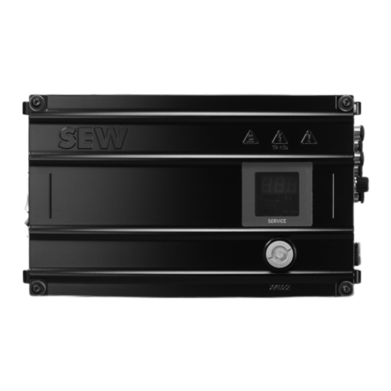
Device structure Device overview Device overview The following figure provides an example of an overview of the most important device components and the position of the labels on the device: 9007225931086091 Status and error codes label Caution signs Status display and infrared interface Connection block (connections depend on the device design) Service interface PE connection... -
Page 29: Information On Switching Voltage
Device structure Information on switching voltage Information on switching voltage As of 2019, the device is supplied with a maximum switching voltage (full wave) of AC 500 V at the signal output M. The last 2 digits of the production number SO# on the nameplate indicate the year of manufacture of the device: Type: SO#: XX.XXXXXXXXXX.XXXX.XX... -
Page 30: Nameplate
Device structure Nameplate Nameplate The nameplate lists information about the device type. The following figure shows an example of a nameplate: Type: SO#: Eingang / Input Ausgang / Output D-76646 Bruchsal Made in Germany XX XX XX ML XXXX 27021626497529995 Product name UKCA representative Designation according to WEEE directive... -
Page 31: Designation Plates
Device structure Designation plates Designation plates 4.6.1 Status and error code plate You will find the most important status and error codes on the status and error code plate. For further information, refer to chapter "Status and fault messages" (→ 2 80). 28733298443 Warning signs Caution signs must be attached at various points on the device to warn about particu- lar hazards. - Page 32 Device structure Accessories INFORMATION The scope of delivery does not include accessories, such as installation and mount- ing material or connection cables. If you are unsure about the accessories you require, contact SEW‑EURODRIVE. For further information accessories, refer following documentation: ®...
- Page 33 Device structure Accessories Use of braking resistors INFORMATION For the device variant with control via a 3-wire brake (PHE..B-15-3..) in combination with a motor with 3-wire brake (e.g. motors from SEW‑EURODRIVE), the brake coil is used as braking resistor. Do not connect any external braking resistor in this case. If a motor without holding brake is connected in the device variant with control for a 2- wire brake, SEW‑EURODRIVE recommends connecting a braking resistor.
-
Page 34: Mechanical Installation
Mechanical installation Requirements Mechanical installation Requirements WARNING Risk of crushing if the load falls. Severe or fatal injuries. • Do not stand under the load. • Secure the area where loads can fall down. • Trained specialists perform the installation. •... -
Page 35: Mounting Position
Mechanical installation Mounting position Mounting position The following figure shows permitted and not permitted mounting positions: 9007211266973707 [1] Permitted mounting position, vertical [2] Impermissible mounting positions Minimum clearance INFORMATION • Observe the following minimum clearances during installation: – When connecting the cables and plug connectors –... -
Page 36: Cooling
Mechanical installation Cooling 9007208973116043 The following table lists the minimum clearances. Housing dimensions are listed in chapter "Technical data" (→ 2 95). Clearance Function Size A: Back of the housing Cut-out for contacts of the conductor rail = 19.5 mm, X = 81 mm, 2 = 102.5 mm 3 = 175 mm, Y = 57 mm, = 91 mm... -
Page 37: Installation
Mechanical installation Installation Installation WARNING Electric shock from live connections. Severe or fatal injuries. • Prevent contact with the feed plug X1261 at the rear of the device using design measures. For further information, refer to chapter "X1261: AC 400 V contact conductor connection" (→ 2 56). - Page 38 Mechanical installation Installation 5.5.1 Fixed angle brackets The following figure shows the main mounting elements and dimensions: 377.1 18014410445761931 Mounting surface Angle bracket Device Tapped holes Mounting the angle brackets To mount the angle brackets (part number 28218248), use the EMS mounting kit (part number 18220789) with: ü...
-
Page 39: Electrical Installation
Electrical installation Installation notes Electrical installation Installation notes NOTICE Ground fault at motor or brake output. Damage to property. • During installation, avoid conductive connections between motor and brake out- put and the ground potential. Observe the following points for electrical installation: •... -
Page 40: Ul-Compliant Installation
Electrical installation UL-compliant installation UL-compliant installation INFORMATION Due to UL requirements, the following chapter is always printed in English, indepen- dent of the language of the documentation. Warnings are also printed in French. 6.4.1 (Field wiring) Power terminals Use 75 °C copper wire only. 6.4.2 Short circuit current rating Suitable for use on a circuit capable of delivering not more than 5000 rms symmetrical... -
Page 41: Environmental Rating
Electrical installation UL-compliant installation The trip current is adjusted to 140 % of the rated motor current. For further informa- tion, refer to chapter "Technical data". 6.4.5 Environmental rating Type 1 6.4.6 Wiring diagrams For wiring diagrams, refer to chapter "Electrical installation". ®... -
Page 42: Electromagnetic Compatibility (Emc)
Electrical installation Electromagnetic compatibility (EMC) Electromagnetic compatibility (EMC) For further information on EMC-compliant installation, refer to the following documen- tation: "Drive Engineering – Practical Implementation, Electromagnetic Compatibility (EMC) in Drive Engineering". 6.5.1 EMC category INFORMATION The product can cause EMC interference within the permitted limit range according to EN 61800‑3. -
Page 43: Protective Measures Against Electrical Hazards
Electrical installation Protective measures against electrical hazards Protective measures against electrical hazards 6.7.1 Connection points for mobile applications For mobile applications, the type of energy transfer determines how you have to apply preventive measure against electrical hazards. Direct power supply The ground connection protects mobile systems with direct power supply against elec- trical hazard according to IEC 60364‑4‑41. -
Page 44: Installing Ground Connection Or Equipotential Bonding
Electrical installation Protective measures against electrical hazards 6.7.2 Installing ground connection or equipotential bonding WARNING Electric shock due to faulty ground connection or equipotential bonding. Severe or fatal injuries. • Make sure to install the ground connection and equipotential bonding correctly. You have to protect all electrical operating resources such as the device or the motor using ground connection or equipotential bonding. - Page 45 Electrical installation Protective measures against electrical hazards 2. Push the crimp cable lug onto the screw. 3. Tighten the screw with a maximum tightening torque of 2.5 Nm. ® Operating Instructions – MOVIPRO PHE..B-A15-.1X0..B-00...
- Page 46 Electrical installation Protective measures against electrical hazards Device with braking resistor INFORMATION For the device variant with control via a 3-wire brake (PHE..B-15-3..) in combination with a motor with 3-wire brake (e.g. motors from SEW‑EURODRIVE), the brake coil is used as braking resistor. Do not connect any external braking resistor in this case. If a motor without holding brake is connected in the device variant with control for a 2- wire brake, SEW‑EURODRIVE recommends connecting a braking resistor.
- Page 47 Electrical installation Protective measures against electrical hazards Installing the PE 11951066763 M5 × 10 screw Crimp cable lug for M5 (PE connection cable of the device) Crimp cable lug for M5 (PE connection cable of the braking resistor) Shield terminal Housing Braking resistor cable Female push-on connector ü...
- Page 48 Electrical installation Protective measures against electrical hazards Leakage currents Leakage currents ≥ AC 3.5 mA/DC 10 mA may occur during normal operation. To avoid dangerous shock currents in accordance with EN 61800-5-1, strictly observe the following: • The protective earth (PE) connection must meet the requirements for systems with high earth-leakage currents.
-
Page 49: Using Prefabricated Cables
Electrical installation Using prefabricated cables Using prefabricated cables SEW‑EURODRIVE uses prefabricated cables for certifications, type tests and ap- proval of the devices. The cables provided by SEW‑EURODRIVE fulfill all require- ments necessary to ensure that the device and all connected components function properly. -
Page 50: Selecting Line Fuses
Electrical installation Line components 6.9.2 Selecting line fuses Install the fuses at the beginning of the supply line behind the supply bus junction. Observe the following when designing the line fuses: • Design the fuses according to the current carrying capacity of the conductor rail in use. -
Page 51: Terminal Strips
Electrical installation Terminal strips 6.10 Terminal strips WARNING Electric shock when disconnecting or connecting voltage-carrying plug connectors. Severe or fatal injuries. • Disconnect all supply voltages. • Make sure that the device is de-energized. • Never plug or unplug the plug connectors while they are energized. INFORMATION For further information on the individual connections and connection cables, refer to chapter "Electrical connections" (→ 2 54). -
Page 52: Connection Site For Motor Connection
Electrical installation Terminal strips 6.10.1 Connection site for motor connection ® Motor connection HAN Q8/0 Connection Function Type designation Motor with brake control [1] X2011 PHE1.B-...-...‑.. ® Motor connection HAN Connection Function Type designation Motor with brake control [1] X2013 PHE2.B-...-...-.. - Page 53 Electrical installation Terminal strips Communication package 2 Connection Function Type designation [1] X4441 M12 parameter memory Digital input – communica- [2] X5002_2 tion and control unit Digital inputs/outputs – com- [3] X5002_1 munication and control unit PHE.2B‑...‑...‑.. RS485 interface – external [4] X4011 (with DC 24 V) Digital input –...
-
Page 54: Electrical Connections
Electrical installation Electrical connections 6.11 Electrical connections 6.11.1 Representation of connections The diagrams show the contact end of the connections. 6.11.2 Connection cables Connection cables are not included in the delivery. Prefabricated cables for connecting SEW‑EURODRIVE components can be ordered. For each connection, the available prefabricated cables are listed. -
Page 55: Cable Structure
Electrical installation Electrical connections 6.11.3 Cable structure Diagram The following table shows the cable structure based on an example: Figure Meaning Cable shield Number of core pairs (in twisted cables only) Number of cores G – with protective earth, green-yellow X - without protective earth 0.25 Core cross section in mm... -
Page 56: X1261: Ac 400 V Contact Conductor Connection
Electrical installation Electrical connections 6.11.4 X1261: AC 400 V contact conductor connection WARNING Electric shock from blank live connections. Severe or fatal injuries. • Use safe, insulated female push-on connectors for installation. • To avoid coming into contact with unused male push-on connectors, you have to install the touch guard on unused male push-on connectors. - Page 57 Electrical installation Electrical connections Wiring diagram Name Function Braking resistor (+) Braking resistor (-) PE connection Signal output M Line connection phase X/jumper to signal contact con- trol This phase is used for the signal output M. Line connection phase Y Line connection phase Z C2/n.c.
- Page 58 Electrical installation Electrical connections Example: Reference of the control input to L X1261 9007229981456139 Example: Reference of the control input against L X1261 27021628490942475 ® Operating Instructions – MOVIPRO PHE..B-A15-.1X0..B-00...
-
Page 59: X1551: Dc 24 V Connection For External Operating Switches
Electrical installation Electrical connections 6.11.5 X1551: DC 24 V connection for external operating switches Function DC 24 V connection for external operating switches Connection type M12, 5-pin, female, A-coded Connection image Name Function +24V DC 24 V output 0V24_SW 0V24 reference potential – switched 0V24 0V24 reference potential +24V_SW... -
Page 60: X2011: Motor With Brake Control
Electrical installation Electrical connections 6.11.6 X2011: Motor with brake control NOTICE Damage or malfunction due to motors with built-in brake rectifiers. Damage to the drive system or its environment. • Do not use motors with built-in brake rectifiers in conjunction with this device. Function Power connection for motor with brake up to 4 kW Connection type... - Page 61 Electrical installation Electrical connections Cables Length/installation Type Component type Part number: 18125794 Cable structure: 4G1.5 Variable length D/1.5 Motor ® Q 8/0 ↔ open (terminal box connection M4) Part number: 18127681m Cable structure: 4G1.5 Variable length D/1.5 Motor ® Q 8/0 ↔ IS m Part number: 18127703 W Variable length D/1.5 Motor...
- Page 62 Electrical installation Electrical connections Cables Length/installation Type Component type Part number: 18164234 Variable length D/1.5 Motor ® Q 8/0 ↔ open (terminal box connection M4) Part number: 18164250 W Variable length D/1.5 Motor ® Q 8/0 ↔ IS W Part number: 18164269 Variable length D/1.5 Motor ® Q 8/0 ↔ ASB8 Part number: 18164285 Variable length...
- Page 63 Electrical installation Electrical connections Conductor assignment Part number Signal name Core color Black/U1 Black/V1 Black/W1 Black/1 18125794 (straight con- nector) Black/2 18164234 (angled con- Black/3 nector) Black/4 Black/5 PE connection Green-yellow + shield end (Inner shield) Connecting the hybrid cable The following figure shows the connection of the hybrid cable to the terminal box of the motor.
-
Page 64: X2013: Motor With Brake Control
Electrical installation Electrical connections 6.11.7 X2013: Motor with brake control NOTICE Damage or malfunction due to motors with built-in brake rectifiers. Damage to the drive system or its environment. • Do not use motors with built-in brake rectifiers in conjunction with this device. Function Power connection for motor with brake up to 4 kW Connection type... - Page 65 Electrical installation Electrical connections Connection cables Cable Length/installation Type Component type Part number: 18164242 Variable length D/1.5 DRS71 DRE80 – DRE90 DRN80 – DRN90 ® 10 E ↔ open (terminal box connection M4) Part number: 18164277 W DRS71W DRE80 – DRE90W DRN80 – DRN90W Variable length D/1.5 ® 10 E ↔ IS W Part number: 18164323 m DRS71m DRE80 – DRE90m DRN80 – DRN90m...
-
Page 66: X4011: Rs485 Interface - External
Electrical installation Electrical connections 6.11.8 X4011: RS485 interface – external Function RS485 interface for external components Connection type M12, 5-pin, female, B-coded Connection diagram Assignment Name Function +24V DC 24 V output RS485 data line (-) Reference potential RS485 data line (+) res. -
Page 67: X4022: Rs485 Interface - Service
Electrical installation Electrical connections 6.11.9 X4022: RS485 interface – service Function RS485 service interface Connection type RJ10 Wiring diagram Name Function Reference potential RS485 data line (-) RS485 data line (+) DC 5 V output Connection component USM21A interface adapter Part number: 28231449 Connection: RJ10 34171599243 ®... -
Page 68: 6.11.10 X4441: M12 Parameter Memory
Electrical installation Electrical connections 6.11.10 X4441: M12 parameter memory INFORMATION To use an unwritten parameter memory on an already configured device, the device must be restarted to apply the configuration. Function Interface for connecting the M12 parameter memory Connection type M12, 5-pin, male, A-coded Wiring diagram Name... -
Page 69: 6.11.11 X5002_1: Digital Inputs/Outputs - Communication And Control Unit
Electrical installation Electrical connections 6.11.11 X5002_1: Digital inputs/outputs – communication and control unit Function Digital inputs/outputs of the communication and control unit Connection type M12, 5-pin, female, A-coded Connection image Name Function +24V DC 24 V output DIO01 Digital input/digital output 01 0V24 0V24 reference potential DIO00... -
Page 70: 6.11.13 X5002_3: Digital Input - Communication And Control Unit
Electrical installation Electrical connections 6.11.13 X5002_3: Digital input – communication and control unit Function Digital input of communication and control unit Connection type M12, 5-pin, female, A-coded Connection image Name Function +24V DC 24 V output DI05 Digital input 05 0V24 0V24 reference potential DI04... -
Page 71: 6.11.15 X5003: Digital Input - Communication And Control Unit
Electrical installation Electrical connections 6.11.15 X5003: Digital input – communication and control unit Function Digital input of communication and control unit Connection type M12, 8-pin, female, A‑coded Connection image Name Function DI04 Digital input 04 DI05 Digital input 05 DI06 Digital input 06 DI07 Digital input 07... -
Page 72: 6.11.16 X5502: Safe Disconnection - Input
Electrical installation Electrical connections 6.11.16 X5502: Safe disconnection – input WARNING Risk of injury due to non safety-related disconnection of the device if the connection is jumpered. Severe or fatal injuries. • Jumper this connection only if the device will not perform any safety functions ac- cording to EN ISO 13849‑1. - Page 73 Electrical installation Electrical connections Connection cable Cable Length/installation Component type Part number: 28129261 Terminal box of the safety Cable design: ((2xAWG24)+(2xAWG22) relay/safety controller Variable length M12, 5-pin, male, A‑coded ↔ M12, 5-pin, male, A‑coded Part number: 28129253 Terminal box of the safety Cable design: (2x0.75) relay/safety controller...
-
Page 74: Startup
Startup For your safety Startup For your safety WARNING Risk of injury due to uncontrolled device behavior caused by ineffective emergency switching off circuit. Severe or fatal injuries. • Have the installation carried out only by qualified personnel. WARNING Risk of injury due to device malfunction caused by incorrect device setting. Severe or fatal injuries. -
Page 75: Requirements
Startup Requirements INFORMATION To ensure fault-free operation, do not disconnect or connect signal cables during operation. Requirements • You have installed the unit correctly both mechanically and electrically. • The system and connected drives must be configured correctly. • Safety measures prevent accidental drive startup. •... -
Page 76: Device Configuration
Startup Device configuration Device configuration 7.4.1 Software Use the latest version of the following software to make all the required settings: ® "MOVIVISION EMS basic parameterizable plant software". 7.4.2 Additional information ® For further information, refer to the following documentation: "MOVIVISION EMS ba- sic parameterizable plant software"... -
Page 77: Operation
Operation For your safety Operation For your safety WARNING Electric shock caused by dangerous voltages at the connections, cables and motor terminals. When the device is switched on, dangerous voltages are present at the connections as well as at any connected cables and motor terminals. This also applies even when the device is inhibited and the motor is at standstill. -
Page 78: Relative Cyclic Duration Factor (Cdf)
Operation Relative cyclic duration factor (cdf) INFORMATION Connect all 3 phases (L1, L2, L3). Deactivated phase failure detection may result in unwanted operating behavior. For further information, refer to the following documen- ® tation: "MOVIVISION EMS basic parameterizable plant software" manual. INFORMATION To ensure fault-free operation, the M12 parameter memory must be plugged in. -
Page 79: Duty Type S2
Operation Duty cycles 8.3.2 Duty type S2 Short-time duty: Operation at constant loading condition for a limited, given time fol- lowed by a time at rest. The motor returns to ambient temperature during the rest period. P, ϑ ϑ ϑ 2325835787 8.3.3 Duty type S3... -
Page 80: Status And Fault Messages
Operation Status and fault messages Status and fault messages The status display of the device displays the following information depending on para- meterization and operating state: • In automatic mode: – Active travel command – Active travel command and speed limitation –... - Page 81 Operation Status and fault messages State Represen- Meaning tation Distance (long field) Distance • F89: Nothing detected (distance ≥ 8.9 m) • F0 – F88: Distance to the vehicle in front in decimeter steps The distance sensor determines the distance to the vehicle in front. The reflector is fastened on the vehicle in front.
- Page 82 Operation Status and fault messages State Represen- Meaning tation Manual operation Establishing a connection with infrared re- mote control. This display alternates with the device ID. For further information, refer to ® the following documentation: "MOVIVISION EMS basic – parameterizable plant software" manual.
-
Page 83: List Of Faults
Operation Status and fault messages 8.4.2 List of faults In case of a malfunction, the status display of the device displays the following fault codes. Code Meaning Possible cause Measure Overcurrent • Short circuit at frequency in- • Check the connection between the verter output frequency inverter output and the motor as well as the motor winding... - Page 84 Operation Status and fault messages Code Meaning Possible cause Measure DC link voltage too • Faulty connection between • Check the braking resistor/brake coil brake coil/braking resistor connection. Correct, if necessary. high • Reset error by switching the device off or via error reset function. •...
- Page 85 Operation Status and fault messages Code Meaning Possible cause Measure Thermal overload of • Ambient temperature too high • Lower ambient temperature. motor • Reset the error by switching off the operating switch. • Heat build-up at the motor • Prevent heat build-up.
- Page 86 Operation Status and fault messages Code Meaning Possible cause Measure Overcurrent • Short circuit at frequency in- • Check the connection between the verter output frequency inverter output and the motor as well as the motor winding for short circuits. •...
- Page 87 Operation Status and fault messages Code Meaning Possible cause Measure M12 parameter M12 parameter memory connect- • Ensure that the M12 parameter memory is always correctly connect- memory connection ed or disconnected during opera- ed during operation. tion • Check that the union nut on the M12 parameter memory unit is positioned securely.
-
Page 88: Status Leds
Operation Status and fault messages Code Meaning Possible cause Measure Unwanted or too • Timeout exceeded • Search for and eliminate cause and/ or check the "Monitoring delay" pa- long applied signal rameter on the "Limit value defini- combination for tion"... -
Page 89: Fault Information
Operation Fault information LED state Description Positive half wave com- Is lit red The device receives positive half mand waves from the command rail. Phase failure Is lit red There is a phase failure. Software status Flashes red The device software on the con- trol is operating. -
Page 90: Fault Memory
Operation Fault information 8.5.1 Fault memory The error memory stores the 10 most recent error messages. The following information is stored when a failure occurs: • Timestamp • Current command (positive/negative half-wave or full wave) • Device status • Error that has occurred (error code) •... -
Page 91: Service
Service Inspection/maintenance Service Inspection/maintenance INFORMATION Never open the device. Only SEW‑EURODRIVE may perform repairs. The device is maintenance-free. SEW‑EURODRIVE does not stipulate any regular in- spection work. However, it is recommended that you check the following components regularly: • Connection cable: If cables become damaged or fatigued, replace them immediately. -
Page 92: Cleaning
Service Cleaning Cleaning Before cleaning the device, disconnect it from the grid. Disconnect the conductor rail from the power if required. Clean the device only with solvent-free cleaning agent. Status display The status display shows status and error messages and thus enables you to record the current state of the device. -
Page 93: Shutdown
Service Shutdown Shutdown WARNING Electric shock due to charged capacitors. Severe or fatal injuries. • Observe a minimum switch-off time after disconnecting the supply voltage: 10 minutes. To shut down the device, disconnect it from the power supply using appropriate mea- sures. -
Page 94: Waste Disposal
Service Waste disposal 9.10 Waste disposal Dispose of the product and all parts separately in accordance with their material struc- ture and the national regulations. Put the product through a recycling process or con- tact a specialist waste disposal company. If possible, divide the product into the follow- ing categories: •... -
Page 95: Technical Data
Technical data General Technical data 10.1 General Basic device Electromagnetic compatibility Interference emission: C3 to EN 61800‑3 Interference immunity: 2. Environment (industrial) Ambient temperature without +5 to +40 °C (non-condensing) derating Device is thermally intrinsically safe, if the heat sink temperature is too high, the device is switched off with the error message "Overtemperature". Ambient temperature with de- +40 to +60 °C rating... -
Page 96: Current Reduction (Derating)
Technical data Current reduction (derating) 10.2 Current reduction (derating) The following diagram shows how to reduce the output current in dependence of in- stallation altitude and ambient temperature for a PWM of 4 kHz. Refer to chapter "Technical data" (→ 2 95) for a detailed description of the parameters. Also observe the "Restrictions of use" (→ 2 12) and the reduction of the line voltage by 6 V per 100 m. -
Page 97: Input Data
Technical data Input data 10.3 Input data Current supply Supply type 3-phase AC connection, TT or TN supply system with directly grounded star point Input voltage range 3 × AC 380 – 500 V Rated supply voltage 3 × AC 400 V Nominal input current AC 3.5 A Rated supply frequency 50 – 60 Hz Maximum permitted rated 5 kA... -
Page 98: Output Data
Technical data Output data Technical data safety-related 24 V supply voltage Min. Typical Max. Unit Time from disconnecting the 24 V supply until – the deactivation of the rotating field 10.4 Output data General Operating mode S1 (IEC 60034‑1) Nominal output current I AC 4 A Minimum permitted braking re- 150 Ω... - Page 99 Technical data Output data Motor protection functions Motor overcurrent protection • Trigger threshold 140% of the motor current with time delay • Tripping time: 60 –134 s Ground fault monitoring The device does not have ground fault monitoring. For further information, refer to chapter "Installation notes" (→ 2 39). 1) Depending on speed and start temperature INFORMATION The total current of all external 24 V consumers must not exceed 500 mA.
-
Page 100: Safety-Related Characteristic Value Sto
Technical data Safety-related characteristic value STO 10.5 Safety-related characteristic value STO Characteristic safety values Approved safety classes Performance Level d to EN ISO 13849‑1 SIL 2 to EN 61800‑5‑2 Probability of dangerous failure per hour (= 0 (fault exclusion) PFHd value) Service life or proof test interval in accordance 20 years, after which the component must be replaced with EN 61508 with a new one... - Page 101 Technical data Motor types Power rat- Motor types Brake, Brake, op- standard tion 0.37 kW DT71D4, 50 Hz, 400 V (IEC) BMG05 – DZ71D4, 60 Hz, 380 V (ABNT) BE05 BMG05 DRS71S4, 60 Hz, 380 V (ABNT) BE05 DRS71S4, 50/60 Hz (global) BE05 DRN71M4, 50/60 Hz (global) BE05 DRS71S4, 50 Hz, 400 V (IEC) BE05 DRS71S4, 60 Hz, 460 V (IEC) BE05...
- Page 102 Technical data Motor types Power rat- Motor types Brake, Brake, op- standard tion 0.75 kW DT80N4, 50 Hz, 400 V (IEC) BMG1 – DZ80N4, 60 Hz, 380 V (ABNT) – BMG1 DRE80S4, 60 Hz, 380 V (ABNT) BE05 DRE80M4, 50/60 Hz (global) BE05 DRN80M4, 50/60 Hz (global) BE05 DRS80S4, 50 Hz, 400 V (IEC) BE05 DRS80S4, 60 Hz, 460 V (IEC) BE05...
-
Page 103: Marks
Technical data Marks Power rat- Motor types Brake, Brake, op- standard tion 1.5 kW DT90L4, 50 Hz, 400 V (IEC) BMG2 – (star con- DZ90L4, 60 Hz, 380 V (ABNT) – BMG2 nection DRE90M4, 60 Hz, 380 V (ABNT) only) DRE90L4, 50/60 Hz (global) DRN90L4, 50/60 Hz (global) DRS90M4, 50 Hz, 400 V (IEC) DRS90M4, 60 Hz, 460 V (IEC) DRE90L4, 50 Hz, 400 V (IEC) DRE90L4, 60 Hz, 460 V (IEC) -
Page 104: Dimension Drawings
Technical data Dimension drawings Mark Definition The China RoHS mark declares compliance with the directive SJ/ T 11364-2014 regarding the restriction of use of certain hazardous sub- stances in electrical and electronic equipment and its packaging. The UL and cUL markings state UL approval. cUL is equally eligible for approval by the CSA. - Page 105 Technical data Dimension drawings The dimension drawing shows the mechanical dimensions of the device in mm: Ø 6.5 4xM5 M8x16 (4x) 21.5 375.5 2xM6 9007208663659019 ® Operating Instructions – MOVIPRO PHE..B-A15-.1X0..B-00...
-
Page 106: Device With Motor Connection Han 10E
Technical data Dimension drawings ® 10.8.2 Device with motor connection HAN INFORMATION For the connections, connection cables and connected components, observe a clear- ance of 120 mm to the side. The dimension drawing shows the mechanical dimensions of the device in mm: Ø... -
Page 107: Mounting Bracket
Technical data Dimension drawings 10.8.3 Mounting bracket 9007211204068235 ® Operating Instructions – MOVIPRO PHE..B-A15-.1X0..B-00... -
Page 108: Index
Index Index Numerical Cooling .............. 36 Derating............ 12, 96 24 V supply, safety-related ........ 97 Installation altitude........ 12, 96 Copyright notice ............ 9 Accessories ............ 31 Ambient temperature ........... 95 Decimal separator .......... 8 Angle bracket ............ 38 Degree of protection .......... 95 Assembly Derating ............ - Page 109 Index Frequency inverter .......... 90 Cooling ............ 36 Fault messages .......... 89 Installation ............ 37 Functionality ........... 89 Minimum clearance ........ 35 Functional safety technology Mounting position ........... 35 Safety note ............. 13 Waste heat ............. 36 Fuse .............. 50 Minimum clearance ..........
- Page 110 Index Safety controller, requirement for ...... 24 Safety functions ........... 13 Tapped holes............ 38 Safety notes Target group ............ 11 Application............ 12 Technical data ............. 95 Assembly............ 15 Input data ............ 97 Designated use .......... 12 Motor types........... 100 Installation ............ 15 Output data.............
- Page 116 SEW-EURODRIVE—Driving the world SEW-EURODRIVE GmbH & Co KG Ernst-Blickle-Str. 42 76646 BRUCHSAL GERMANY Tel. +49 7251 75-0 Fax +49 7251 75-1970 sew@sew-eurodrive.com www.sew-eurodrive.com...
Need help?
Do you have a question about the MOVIPRO PHE B-A15-1X0 B-00 Series and is the answer not in the manual?
Questions and answers