SEW-Eurodrive MOVIFIT FC Operating Instructions Manual
Decentralized drive systems
Hide thumbs
Also See for MOVIFIT FC:
- Operating instructions manual (228 pages) ,
- Manual (178 pages) ,
- Manual (38 pages)

Related Manuals for SEW-Eurodrive MOVIFIT FC


Summary of Contents for SEW-Eurodrive MOVIFIT FC
- Page 1 Drive Technology \ Drive Automation \ System Integration \ Services Operating Instructions Decentralized Drive Systems ® MOVIFIT Edition 07/2012 17060826 / EN...
- Page 2 SEW-EURODRIVE—Driving the world...
-
Page 3: Table Of Contents
Contents Contents General Information .................... 6 How to use this documentation ..............6 Structure of the safety notes ............... 6 Rights to claim under warranty ..............7 Exclusion of liability..................7 Copyright..................... 7 Product names and brands ................. 7 Safety Notes ......................8 Preliminary information ................ - Page 4 Contents Electrical Installation ..................40 General information .................. 40 Installation planning taking EMC aspects into account ......40 Installation instructions (all variants) ............42 Additional installation instructions for group drives ........49 Installation topology (example) ..............50 Standard ABOX MTA...-S02.-...-00 ............51 Hybrid ABOX MTA...-S42.-...-00 ...............
- Page 5 Contents Technical Data....................151 CE marking, UL approval and C-Tick ............. 151 Variant with operating point 400 V / 50 Hz..........152 Variant with operating point 460 V / 60 Hz..........153 Electronics data ..................154 Binary inputs ................... 154 Binary outputs DO00 –...
-
Page 6: General Information
General Information How to use this documentation General Information How to use this documentation This documentation is an integral part of the product and contains important information on operation and service. The documentation is intended for all employees who perform assembly, installation, startup and service work on the product. -
Page 7: Rights To Claim Under Warranty
General Information Rights to claim under warranty Rights to claim under warranty A requirement of fault-free operation and fulfillment of any rights to claim under limited warranty is that you adhere to the information in the documentation. Read the documen- tation before you start working with the unit. -
Page 8: Safety Notes
Safety Notes Preliminary information Safety Notes The following basic safety notes must be read carefully to prevent injury to persons and damage to property. The operator must ensure that the basic safety notes are read and adhered to. Ensure that persons responsible for the system and its operation, as well as persons who work independently on the unit, have read through the operating instruc- tions carefully and understood them. -
Page 9: Designated Use
Safety Notes Designated use Designated use ® MOVIFIT is a component intended for installation in electrical systems or machines. ® In case of installation in machines, startup of MOVIFIT units (i.e. start of designated operation) is prohibited until it is determined that the machine meets the requirements stipulated in the Machinery Directive 2006/42/EC. -
Page 10: Transportation And Storage
Safety Notes Transportation and storage Transportation and storage You must observe the notes on transportation, storage and proper handling. Observe the climatic conditions as stated in the "Technical Data" sections. Installation The units must be installed and cooled according to the regulations and specifications in the corresponding documentation. -
Page 11: 2.10 Operation
Safety Notes Operation 2.10 Operation ® Systems into which MOVIFIT is installed must, if necessary, be equipped with addi- tional monitoring and protection devices according to applicable safety regulations, ac- cident prevention regulations, etc. Additional protective measures may be necessary for ®... -
Page 12: Unit Structure
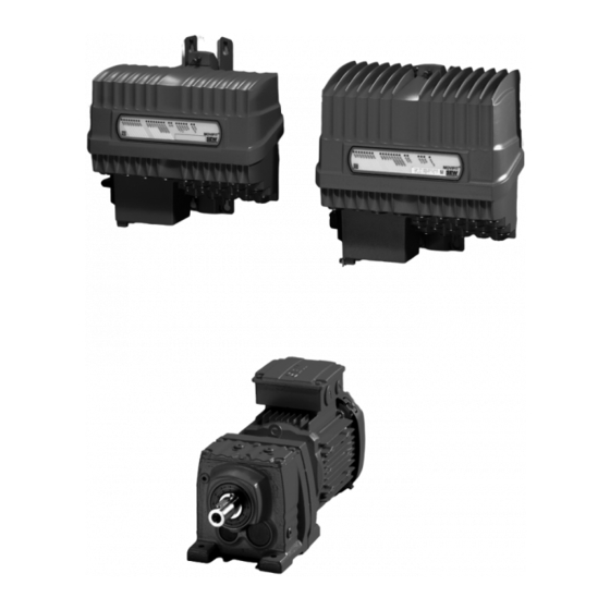
Unit Structure ® MOVIFIT Unit Structure ® MOVIFIT ® MOVIFIT FC is a decentralized drive controller with integrated frequency inverter for controlling gearmotors. ® The following figure shows a standard MOVIFIT FC unit of size 1: 4285335307 EBOX (active electronics unit) ABOX (passive connection unit) ®... -
Page 13: Overview Of Connection Configurations
Unit Structure Overview of connection configurations Overview of connection configurations ® The following figures show the MOVIFIT FC variants described in these operating in- structions: EBOX ABOX Variant MTA...-S02.-...-00 Standard ABOX With terminals and cable bushings MTA...-S42.-...-00 MTF...-...-00 Hybrid ABOX With M12 for I/Os MTA...-S52.-...-00 Size 1... - Page 14 Unit Structure Overview of connection configurations EBOX ABOX Variant MTA...-I55.-...-00 Hybrid ABOX With 1 round connector (Intercontec) 1 x downwards motor output and M12 for I/Os and bus MTA...-G55.-...-00 MTF...-...-00 Hybrid ABOX With 1 round connector (Intercontec) 1 x motor output at the front and M12 for I/Os and bus Size 1 MTA...-I65.-...-00...
-
Page 15: Ebox (Active Electronics Unit)
Unit Structure EBOX (active electronics unit) EBOX (active electronics unit) ® The MOVIFIT FC EBOX is a closed electronics unit with communication interface, bi- nary inputs and outputs (I/Os), and frequency inverter: EBOX " MTF...-..-00" 1 2 3 4 5 6 1 2 3 4 9007200067263755 [A] Size 1... -
Page 16: Abox (Passive Connection Unit)
Unit Structure ABOX (passive connection unit) ABOX (passive connection unit) ® The following figure shows an example of the MOVIFIT FC ABOX: ABOX " MTA...-..-00" I O N 812524427 Mounting rail Connection to EBOX Protection cover Maintenance switch (triple lock) DIP switch S1 for bus termination DIP S3 switches for SBus bus termination DIP switch S2 for bus address (PROFIBUS and DeviceNet variants only) -
Page 17: Hygienic Plus Variant (Optional)
Unit Structure Hygienicplus variant (optional) plus Hygienic variant (optional) 3.5.1 Properties plus The Hygienic variant has the following characteristics: ® • IP66 in accordance with EN 60529 and IP69K according to DIN 40050-9 (MOVIFIT housing closed and all cable bushings sealed according to the relevant degree of protection) •... - Page 18 Unit Structure Hygienicplus variant (optional) ® The following figure shows the additional features of MOVIFIT units in the optional plus Hygienic variant: EBOX " MTF12...-..-00" ABOX "MTA12...-S02.-...-00" [10] [11] 9007200067232139 [1] EBOX with special surface treatment (only available in one color) [2] Signal plug connector with gasket [3] Gasket between ABOX and cover plate [4] Power plug connector with gasket...
-
Page 19: Movifit ® With L10 Profinet Interface Scrj/Pof
Unit Structure ® MOVIFIT with L10 PROFINET interface SCRJ/POF ® MOVIFIT with L10 PROFINET interface SCRJ/POF 3.6.1 Unit structure ® The following figure shows MOVIFIT with L10 PROFINET interface SCRJ/POF (POF option L10): 9007202682186763 ® MOVIFIT Special mounting rail POF option L10 (POF = Polymer Optical Fiber) Status LEDs X30 / X31 connections PROFINET POF Electrical connections between the POF option L10 and the ABOX... -
Page 20: Type Designation Movifit ® Fc
Unit Structure ® Type designation MOVIFIT ® Type designation MOVIFIT 3.7.1 EBOX Nameplate The following figure shows an example of the outer nameplate of the EBOX of ® MOVIFIT 4666063115 [1] EBOX type designation [2] Serial number [3] Status field The following figure shows an example of the inner nameplate of the EBOX of ®... - Page 21 Unit Structure ® Type designation MOVIFIT ® Type designation The following table shows an example of the type designation of the EBOX of MOVIFIT MT F 11 A 015- 50 3 - P1 0 A - 00 / S11 EBOX option S11 = PROFIsafe option S11 EBOX design 00 = DT/DV motor 400 V, 50 Hz...
- Page 22 Unit Structure ® Type designation MOVIFIT 3.7.2 ABOX ® Nameplate The following figure shows an example nameplate of the ABOX of MOVIFIT 27021598576803979 ABOX status field Nameplate of POF The following figure shows the nameplate of the POF option L10: option L10 L10 (POF-Option) Made...
- Page 23 Unit Structure ® Type designation MOVIFIT ® Type designation The following table shows an example of the type designation of the ABOX of MOVIFIT MTA11A - 503 - S021 - D01 - 00 / BW1 / M11 ABOX option 2 M11 = Stainless steel mounting rail L10 = PROFINET interface SCRJ / POF (POF option L10) ABOX option 1...
-
Page 24: Mechanical Installation
Mechanical Installation General information Mechanical Installation General information CAUTION Risk of injury due to protruding parts, especially the mounting rail. Risk of cutting or crushing. • Cover sharp and protruding parts, especially the mounting rail, to protect against injury and damage. ®... -
Page 25: Permitted Mounting Position
Mechanical Installation Permitted mounting position Permitted mounting position ® MOVIFIT is attached by means of a mounting platform using the 4 screws already in- stalled in the mounting surface. For detailed information, refer to chapter "Mounting" (page 26). ® The following figure shows the permitted mounting positions for MOVIFIT 90°... -
Page 26: Installation
Mechanical Installation Installation Installation 4.3.1 Mounting rail ® MOVIFIT is equipped with a mounting rail to attach the unit to a level, low-vibration mounting surface using M6 bolts. For bore dimensions of the respective type of fixture, see the following figures. Drilling template for standard mounting rail 7.0 (6x) 13.9 (6x) - Page 27 Mechanical Installation Installation Drilling template for optional mounting rail /M11 7.0 (8x) 13.9 (8x) min. 50 334.4 18014399308791819 INFORMATION • [1] Observe the minimum installation clearance so that the EBOX can be removed from the ABOX. • [2] Observe the minimum installation clearance required to operate the mainte- nance switch and to ensure heat dissipation for the unit.
- Page 28 Mechanical Installation Installation Drilling template for mounting rail (POF option L10) ® The MOVIFIT unit with the special mounting rail is mounted analogously to a unit with mounting rail /M11. However, an additional retaining screw behind the POF option is necessary for this mounting rail, see following figure.
- Page 29 Mechanical Installation Installation 4.3.2 Fastening CAUTION Risk of crushing if the load falls. Severe or fatal injuries. • Do not stand under the load. • Secure the danger zone. CAUTION Risk of injury due to protruding parts. Risk of cutting or crushing. •...
- Page 30 Mechanical Installation Installation 3. Attach the ABOX to the screws with the mounting plate 758565899 Operating Instructions – MOVIFIT® FC...
- Page 31 Mechanical Installation Installation 4. Tighten the screws. CAUTION Risk of injury if the load falls. Minor injuries • Tighten at least 4 wall screws to ensure a secure fit after mounting. 758590731 Operating Instructions – MOVIFIT® FC...
-
Page 32: Central Opening/Closing Mechanism
Mechanical Installation Central opening/closing mechanism Central opening/closing mechanism WARNING ® Danger of burns due to hot surfaces of the MOVIFIT unit. Severe injuries. ® • Do not touch the MOVIFIT until it has cooled down sufficiently. CAUTION Risk of injury if the EBOX falls. Minor injuries. - Page 33 Mechanical Installation Central opening/closing mechanism 2. Remove the EBOX from the ABOX by lifting it upwards. Align the EBOX correctly. EBOX 90° ABOX 813353099 4.4.2 Closing You need a socket wrench (SW8) for the central retaining screw. NOTICE An improperly seated seal in the EBOX creates a strong counterforce ®...
- Page 34 Mechanical Installation Central opening/closing mechanism 3. Check the EBOX for the correct position. NOTICE The central opening/closing mechanism may be damaged. The central opening/closing mechanism may be destroyed. • In all tilted mounting positions, you must guide the EBOX manually when you are closing it.
-
Page 35: Tightening Torques
Mechanical Installation Tightening torques Tightening torques 4.5.1 Blanking plugs Tighten the blanking plugs included in the delivery with 2.5 Nm: 758614667 Operating Instructions – MOVIFIT® FC... - Page 36 Mechanical Installation Tightening torques 4.5.2 EMC cable glands Tighten the EMC cable glands optionally supplied by SEW-EURODRIVE with the follow- ing torques: 758624523 Screw fitting Part number Size Tightening torque EMC cable glands (nickel- 1820 478 3 M16 x 1.5 3.5 Nm to 4.5 Nm plated brass) 1820 479 1...
-
Page 37: Movifit ® Hygienic Plus Variant
Mechanical Installation ® MOVIFIT Hygienicplus variant ® plus MOVIFIT Hygienic variant INFORMATION plus SEW-EURODRIVE guarantees that the Hygienic special surface treatment is free from faults when delivered. Submit a complaint to the shipping company immediately after receiving the unit, if it is damaged. Although the housing surfaces have a high impact resistance, they are to be handled with care. - Page 38 Mechanical Installation ® MOVIFIT Hygienicplus variant plus 4.6.2 Tightening torques of Hygienic variant NOTICE Loss of warranted degree of protection IP69K if the screw plugs are installed incor- rectly or not at all. ® Damage to the MOVIFIT unit. ® •...
- Page 39 Mechanical Installation ® MOVIFIT Hygienicplus variant EMC cable glands Tighten the EMC cable glands optionally supplied by SEW-EURODRIVE with the follow- ing torques: 512772875 Screw fitting Part number Size Tightening torque EMC cable glands (nickel- 1820 478 3 M16 x 1.5 3.0 Nm to 4.0 Nm plated brass) 1820 479 1...
-
Page 40: Electrical Installation
Electrical Installation General information Electrical Installation General information Observe the following notes on electrical installation: • Observe the general safety notes. • Strictly observe all instructions as to the technical data and the permissible condi- tions regarding the place of installation. •... - Page 41 Electrical Installation Installation planning taking EMC aspects into account 5.2.1 Equipotential bonding Regardless of the protective earth connection, it is essential that low-impedance, HF- capable equipotential bonding is provided (see also EN 60204-1 or DIN VDE 0100-540): • Establish a connection over a wide surface ®...
-
Page 42: Installation Instructions (All Variants)
Electrical Installation Installation instructions (all variants) Installation instructions (all variants) 5.3.1 Connecting supply system leads ® • The rated voltage and frequency of the MOVIFIT frequency inverter must corre- spond to the data for the supply system. • Cable cross section according to input current I for rated power (see chapter line "Technical Data"). - Page 43 Electrical Installation Installation instructions (all variants) 5.3.4 Notes on PE connection and/or equipotential bonding WARNING Electric shock due to incorrect connection of PE. Severe, fatal injuries • The permitted tightening torque for the retaining screws is 2.0 – 2.4 Nm. •...
- Page 44 Electrical Installation Installation instructions (all variants) 5.3.5 Definition PE, FE WARNING Electric shock due to incorrect connection of PE to the terminals marked with "F" (functional ground). The FE connections are not designed for this purpose. This means electrical safety is not guaranteed. Severe or fatal injuries.
- Page 45 Electrical Installation Installation instructions (all variants) 3) 24V_P = The 24V_P voltage level supplies the integrated inverter with 24 V. Inverter supply Depending on the application, the 24V_P voltage level can be supplied by 24V_C or 24V_S (via jumpers at X29) or externally. The required jumpers are included in the scope of delivery.
- Page 46 Electrical Installation Installation instructions (all variants) 5.3.7 Plug connectors ® All MOVIFIT plug connectors are illustrated in these operating instructions with view on the contact end. 5.3.8 Operating braking resistors Braking resistors dissipate the energy generated during braking operations and get hot in the process.
- Page 47 Electrical Installation Installation instructions (all variants) 5.3.11 UL-compliant installation Power terminals Note the following points for UL-compliant installation: • Use only 75 °C copper wire. ® • MOVIFIT uses cage clamp terminals. Short circuit cur- Suitable for use in circuits that deliver a maximum of 200,000 A rms: rent rating ®...
- Page 48 Electrical Installation Installation instructions (all variants) 5.3.12 Installation altitude higher than 1000 m above sea level ® MOVIFIT units with supply voltages of 380 to 500 V can be used at altitudes above 1000 m asl up to 4000 m asl under the following conditions: •...
-
Page 49: Additional Installation Instructions For Group Drives
Electrical Installation Additional installation instructions for group drives Additional installation instructions for group drives ® The following figure shows the prescribed installation for group drives with MOVIFIT ® MOVIFIT 1240954123 When installing such group drives, also follow the installation instructions below: •... -
Page 50: Installation Topology (Example)
Electrical Installation Installation topology (example) Installation topology (example) ® The following figure shows the general installation topology of MOVIFIT 400 V 24 V 24 V 400 V ® ® MOVIFIT MOVIFIT DR.. DR.. 5068774155 Operating Instructions – MOVIFIT® FC... -
Page 51: Standard Abox Mta
Electrical Installation Standard ABOX MTA...-S02.-...-00 Standard ABOX MTA...-S02.-...-00 5.6.1 Description The following figure depicts the Standard ABOX with terminals and cable bushings: 9007200067288715 [1] Optional maintenance switch [2] PE connection [3] Diagnostics socket (RJ10) under the screw plug Operating Instructions – MOVIFIT® FC... - Page 52 Electrical Installation Standard ABOX MTA...-S02.-...-00 5.6.2 Variants ® The following variants of the standard ABOX are available for MOVIFIT FC (MTF): • MTA11A-503-S02.-...-00: – Optional internal or external braking resistor – Optional load break switch – Load break switch and line protection The following figure shows the screw connections and plug connectors of the standard ABOX depending on the fieldbus interface: PROFIBUS...
- Page 53 Electrical Installation Standard ABOX MTA...-S02.-...-00 5.6.3 Additional installation instructions for MTA...-S02.-...-00 Permitted connection cross-section and current carrying capacity of the terminals Terminal data X1 / X20 X8 / X9 X25 / X30 / X31 / X35 / X45 / X81 / X91 Connection cross 0.2 –...
- Page 54 Electrical Installation Standard ABOX MTA...-S02.-...-00 Actuating the ter- minals Terminals X1, X20 Connect the conductor Connect the conductor without screwdriver with screwdriver 812407947 812406283 1) Single-wire conductors and flexible conductors with conductor end sleeves can be installed directly (with- out using a tool) up to two cross section sizes below the rated cross section. 2) Untreated, flexible conductors or conductors with small cross sections cannot be directly inserted into the terminal.
- Page 55 Electrical Installation Standard ABOX MTA...-S02.-...-00 Connecting the Observe the following guidelines of the PROFIBUS user organization (Internet: PROFIBUS cable www.profibus.com) for your PROFIBUS installation: ® in MOVIFIT • "Installation guidelines for PROFIBUS DP/FMS", order number 2.111 (German) or 2.112 (English) •...
- Page 56 Electrical Installation Standard ABOX MTA...-S02.-...-00 Connecting the • SEW-EURODRIVE recommends using the shielded and prefabricated SEW hybrid ® hybrid cables cables specifically designed for connecting MOVIFIT to the motor. See chapter "Electrical Installation" / "Hybrid cables". • The outer shield of the hybrid cable must be attached to the housing of the unit using a suitable EMC cable gland.
- Page 57 Electrical Installation Standard ABOX MTA...-S02.-...-00 5.6.4 Terminal positions The following figure shows the position of the terminals in the ABOX: 1 2 3 4 5 6 7 8 2 3 4 [5] X30 (X31) 2 3 4 [6] X35 [7] X50 [10] [12] [11]...
- Page 58 Electrical Installation Standard ABOX MTA...-S02.-...-00 5.6.5 Terminal assignment WARNING Electric shock due to dangerous voltages in the ABOX. The maintenance switch only disconnects the integrated frequency inverter from the ® power supply. Voltage is still present at the terminals of MOVIFIT Severe or fatal injuries.
- Page 59 Electrical Installation Standard ABOX MTA...-S02.-...-00 X20: 24 V supply terminal (24 V power bus) 2 3 4 5 6 11 1 12 12 13 13 14 1415 15 16 1718 2 3 4 1 2 3 4 11 12 13 14 1 2 3 4 5 1 2 3 4 5 6 7 8 12 13 14 15...
- Page 60 Electrical Installation Standard ABOX MTA...-S02.-...-00 X8, X81, X9 and X91: Motor connection terminals WARNING Risk of crushing due to incorrect parameterization of the binary output DB00. Severe or fatal injuries. • If binary output DB00 is used to control the brake, do not change the parameters that define the functions of the binary output.
- Page 61 Electrical Installation Standard ABOX MTA...-S02.-...-00 X29: 24 V distributor terminals WARNING Danger through unexpected unit behavior. When you use terminals X29/5, X29/6, X29/15, and X29/16 for a safe disconnection, you must observe the SEW manual ® "MOVIFIT MC/FC – Functional Safety". Severe or fatal injuries.
- Page 62 Electrical Installation Standard ABOX MTA...-S02.-...-00 X25: I/O terminals 2 3 4 5 6 11 1 12 12 13 13 14 1415 15 16 1718 2 3 4 1 2 3 4 11 12 13 14 1 2 3 4 5 1 2 3 4 5 6 7 8 12 13 14 15 12 13 14 1516 17 18...
- Page 63 Electrical Installation Standard ABOX MTA...-S02.-...-00 2 3 4 5 6 11 1 12 12 13 13 14 1415 15 16 1718 2 3 4 1 2 3 4 11 12 13 14 1 2 3 4 5 1 2 3 4 5 6 7 8 12 13 14 15 12 13 14 1516 17 18 2 3 4...
- Page 64 Electrical Installation Standard ABOX MTA...-S02.-...-00 X35: SBus terminals 2 3 4 5 6 11 1 12 12 13 13 14 1415 15 16 1718 2 3 4 1 2 3 4 11 12 13 14 1 2 3 4 5 1 2 3 4 5 6 7 8 12 13 14 15 12 13 14 1516 17 18...
- Page 65 Electrical Installation Standard ABOX MTA...-S02.-...-00 X45: I/O terminals for safety-related inputs/outputs (only in connection with PROFIsafe option card S11) WARNING Danger through unexpected unit behavior When you are using terminals X45 for safe ® disconnection, you must observe the "MOVIFIT MC/FC –...
- Page 66 Electrical Installation Standard ABOX MTA...-S02.-...-00 X30 and X31: PROFIBUS terminals (only for PROFIBUS variants) 1 2 3 2 3 4 5 6 11 1 12 12 13 13 14 1415 15 16 1718 2 3 4 1 2 3 4 11 12 13 14 1 2 3 4 5 1 2 3 4 5 6 7 8...
- Page 67 Electrical Installation Standard ABOX MTA...-S02.-...-00 X30 and X31: Ethernet plug connector (only for PROFINET-IO, EtherNet/IP or Modbus/TCP variants) 2 3 4 5 6 11 1 12 12 13 13 14 1415 15 16 1718 2 3 4 1 2 3 4 11 12 13 14 1 2 3 4 5 1 2 3 4 5 6 7 8...
- Page 68 Electrical Installation Standard ABOX MTA...-S02.-...-00 X11 / X30: DeviceNet plug connectors / terminals (only for DeviceNet variants) 2 3 4 5 6 11 1 12 12 13 13 14 1415 15 16 1718 1 2 3 4 5 2 3 4 1 2 3 4 11 12 13 14 1 2 3 4 5...
-
Page 69: Hybrid Abox Mta
Electrical Installation Hybrid ABOX MTA...-S42.-...-00 Hybrid ABOX MTA...-S42.-...-00 INFORMATION • The hybrid ABOX is based on the standard ABOX MTA...-S02.-...-00. The following therefore only describes the additional plug connectors in comparison with the standard ABOX. • For a description of the terminals, refer to chapter "Standard ABOX MTA...-S02.- ...-00. - Page 70 Electrical Installation Hybrid ABOX MTA...-S42.-...-00 5.7.2 Variants ® The following variants of the hybrid ABOX are available for MOVIFIT FC (MTF): • MTA11A-503-S42.-...-00: – Optional internal or external braking resistor – Optional load break switch – Load break switch and line protection The following figure shows the cable glands and plug connectors of the hybrid ABOX: PROFIBUS MTA11A-503-S421-...-00...
- Page 71 Electrical Installation Hybrid ABOX MTA...-S42.-...-00 5.7.3 Plug connector positions The following figure shows the plug connectors of the hybrid ABOX: [1] X21 – X24 [1] X25 – X28 [2] X50 3570049547 X21 – X28 Binary inputs/outputs (M12, 5-pole, female, A-coded) Diagnostic interface (RJ10, female, under the screw plug)
-
Page 72: Hybrid Abox Mta
Electrical Installation Hybrid ABOX MTA...-S52.-...-00 Hybrid ABOX MTA...-S52.-...-00 INFORMATION • The hybrid ABOX is based on the standard ABOX MTA...-S02.-...-00. The following therefore only describes the additional plug connectors in comparison with the standard ABOX. • For a description of the terminals, refer to chapter "Standard ABOX MTA...-S02.- ...-00 (page 51). - Page 73 Electrical Installation Hybrid ABOX MTA...-S52.-...-00 5.8.2 Variants ® The following variants of the hybrid ABOX are available for MOVIFIT FC (MTF): • MTA11A-503-S52.-...-00: – Optional internal or external braking resistor – Optional load break switch – Load break switch and line protection The following figure shows the cable glands and plug connectors of the Hybrid ABOX depending on the fieldbus interface: PROFIBUS...
- Page 74 Electrical Installation Hybrid ABOX MTA...-S52.-...-00 5.8.3 Plug connector positions The following figure shows the plug connectors of the hybrid ABOX: PROFIBUS: [1] X11 [2] X12 Ethernet: [3] X11 [4] X12 DeviceNet: [5] X11 [6] X21 – X24 [6] X25 – X28 [7] X50 3570202635 PROFIBUS input...
-
Page 75: Hybrid Abox Mta
Electrical Installation Hybrid ABOX MTA...-S533-...-00/L10 Hybrid ABOX MTA...-S533-...-00/L10 INFORMATION • The hybrid ABOX is based on the standard ABOX MTA...-S02.-...-00. The following therefore only describes the additional plug connectors in comparison with the standard ABOX. • For a description of the terminals, refer to chapter "Standard ABOX MTA...-S02.- ...-00 (page 51). - Page 76 Electrical Installation Hybrid ABOX MTA...-S533-...-00/L10 The following figure shows the mounting rail and POF option L10 from the back: 5057677451 DC 24 V supply Cable gland (connected at the factory) PROFINET IO, port 1 Cable gland (connected at the factory) PROFINET IO, port 2 Cable gland (connected at the factory) POF option L10...
- Page 77 Electrical Installation Hybrid ABOX MTA...-S533-...-00/L10 5.9.2 Variants ® The following variants of the hybrid ABOX are available for MOVIFIT FC (MTF): • MTA11A-503-S53.-..-00/L10: – Optional internal or external braking resistor – Optional load break switch – Optional load break switch and line protection The following figure shows the cable glands and plug connectors of the hybrid ABOX with POF option L10: PROFINET MTA11A-503-S533-...-00/L10...
- Page 78 Electrical Installation Hybrid ABOX MTA...-S533-...-00/L10 5.9.3 Plug connector positions ® The following figure shows the plug connectors of MOVIFIT with POF option L10: MTA11A-503-S533-...-../L10 [2] [3] [5] [6] 5048967563 PROFINET IO interface, port 1 M12, D coding, female (plugged at the factory) PROFINET IO interface, port 2 M12, D coding, female (plugged at the factory)
-
Page 79: Hybrid Abox Mta
Electrical Installation Hybrid ABOX MTA...-S62.-...-00 5.10 Hybrid ABOX MTA...-S62.-...-00 INFORMATION • The hybrid ABOX is based on the standard ABOX MTA...-S02.-...-00. The following therefore only describes the additional plug connectors in comparison with the standard ABOX. • For a description of the terminals, refer to chapter "Standard ABOX MTA...-S02.- ...-00 (page 51). - Page 80 Electrical Installation Hybrid ABOX MTA...-S62.-...-00 5.10.2 Variants ® The following variants of the hybrid ABOX are available for MOVIFIT FC (MTF): • MTA11A-503-S62.-...-00: – Optional internal or external braking resistor – Optional load break switch – Load break switch and line protection The following figure shows the cable glands and plug connectors of the hybrid ABOX: PROFINET EtherNet/IP...
- Page 81 Electrical Installation Hybrid ABOX MTA...-S62.-...-00 5.10.3 Plug connector positions NOTICE The RJ45 socket can be damaged by inserting commercially available RJ45 patch ca- bles without push-pull connector housing. Damage to the RJ45 socket. • Only plug suitable push-pull RJ45 mating connectors according to IEC PAS 61076- 3-117 into push-pull RJ45 sockets.
-
Page 82: Hybrid Abox Mta
Electrical Installation Hybrid ABOX MTA...-I55.-...-00, MTA...-G55.-...-00 5.11 Hybrid ABOX MTA...-I55.-...-00, MTA...-G55.-...-00 INFORMATION • The hybrid ABOX is based on the standard ABOX MTA...-S02.-...-00. The following therefore only describes the additional plug connectors in comparison with the standard ABOX. • For a description of the terminals, refer to chapter "Standard ABOX MTA...-S02.- ...-00 (page 51). - Page 83 Electrical Installation Hybrid ABOX MTA...-I55.-...-00, MTA...-G55.-...-00 5.11.2 Variants ® The following variants of the hybrid ABOX are available for MOVIFIT FC (MTF): • MTA11A-503-I55.-...-00 / MTA11A-503-G55.-...-00 – Optional internal or external braking resistor – Optional load break switch – Optional load break switch and line protection The following figure shows the cable glands and plug connectors of the Hybrid ABOX depending on the fieldbus interface: MTA11A-503-I551-...-00...
- Page 84 Electrical Installation Hybrid ABOX MTA...-I55.-...-00, MTA...-G55.-...-00 5.11.3 Plug connector positions The following figure shows the plug connectors of the hybrid ABOX: PROFIBUS: [1] X11 [2] X12 Ethernet: [3] X11 [4] X12 DeviceNet: [5] X11 MTA11A-503-G55.-...-00: [6] X80 MTA11A-503-I55.-...-00: [6] X80 [7] X21 –...
-
Page 85: Hybrid Abox Mta
Electrical Installation Hybrid ABOX MTA...-I65.-...-00, MTA...-G65.-...-00 5.12 Hybrid ABOX MTA...-I65.-...-00, MTA...-G65.-...-00 INFORMATION • The hybrid ABOX is based on the standard ABOX MTA...-S02.-...-00. The following therefore only describes the additional plug connectors in comparison with the standard ABOX. • For a description of the terminals, refer to chapter "Standard ABOX MTA...-S02.- ...-00 (page 51). - Page 86 Electrical Installation Hybrid ABOX MTA...-I65.-...-00, MTA...-G65.-...-00 5.12.2 Variants ® The following variants of the hybrid ABOX are available for MOVIFIT FC (MTF): • MTA11A-503-I65.-...-00 / MTA11A-503-G65.-...-00: – Optional internal or external braking resistor – Optional load break switch – Optional load break switch and line protection The following figure shows the cable glands and plug connectors of the hybrid ABOX: PROFINET MTA11A-503-I653-...-00...
- Page 87 Electrical Installation Hybrid ABOX MTA...-I65.-...-00, MTA...-G65.-...-00 5.12.3 Plug connector positions NOTICE The RJ45 socket can be damaged by inserting commercially available RJ45 patch ca- bles without push-pull connector housing. Damage to the RJ45 socket. • Only plug suitable push-pull RJ45 mating connectors according to IEC 61076-3- 117 into push-pull RJ45 sockets.
-
Page 88: 5.13 Electrical Connections
Electrical Installation Electrical connections 5.13 Electrical connections 5.13.1 Connection cables Connection cables are not included in the scope of delivery. Prefabricated cables for connection between SEW components can be ordered from SEW-EURODRIVE at any time. They are described in the following sections. Specify the part number and length of the required cable in your order. - Page 89 Electrical Installation Electrical connections 5.13.2 X80: Motor connection (ABOX MTA...I55.-..., MTA...G55.-..., MTA...I65.-..., MTA...G65.-...) The following table shows information about this connection: Function Motor connection Connection type Intercontec 723 H-Tec, 7 + 3-pole, female (downward or to the front) Wiring diagram 4312557451 Assignment Name...
- Page 90 Electrical Installation Electrical connections 5.13.3 X21 – X28: Binary inputs/outputs Variants The number and assignment of binary inputs/outputs depends on • the function level ® • and the fieldbus interface of the MOVIFIT unit. ® I/O variant MOVIFIT variant Function level Fieldbus •...
- Page 91 Electrical Installation Electrical connections Assignment The following table shows information about these connections: Function Binary inputs/outputs of the hybrid ABOX Connection type M12, 5-pole, female, A-coded Wiring diagram 2264816267 I/O variant Assignment (Encoder 1 (Encoder 2 connection) connection) VO24-I VO24-I VO24-II VO24-II DI01...
- Page 92 Electrical Installation Electrical connections Y adapter For connecting 2 sensors/actuators to an M12 plug connector, use a Y adapter with ex- tension. The Y adapter is available from different manufacturers: Manufac- Escha turer: Type: WAS4-0,3-2FKM3/.. 915294347 Manufac- Binder turer: Type: 79 5200 ..
- Page 93 Electrical Installation Electrical connections 5.13.4 X11: PROFIBUS input (ABOX MTA...S52.-..., MTA...I55.-..., MTA...G55.-...) The following table shows information about this connection: Function PROFIBUS input Connection type (M12, 5-pole, male, B-coded) Wiring diagram 2461813259 Assignment Name Function res. Reserved A_IN PROFIBUS data line A res.
- Page 94 Electrical Installation Electrical connections 5.13.6 X11: DeviceNet interface (ABOX MTA...S52.-..., MTA...I55.-..., MTA...G55.-...) The following table shows information about this connection: Function DeviceNet interface Connection type (Micro style connector, male, A-coded) Wiring diagram 2264818187 Assignment Name Function Drain Shield/equipotential bonding DC 24 V input Reference potential CAN_H CAN data line (high)
- Page 95 Electrical Installation Electrical connections 5.13.8 X11, X12: Ethernet interface (ABOX MTA...S62.-..., MTA...I65.-.., MTA...G65.-..) The following table shows information about this connection: Function • PROFINET IO interface • EtherNet/IP IO interface • Modbus/TCP IO interface Connection type Push-pull RJ45 Wiring diagram 2354433675 Assignment Name...
- Page 96 Electrical Installation Electrical connections Closing plug, optional NOTICE Loss of warranted degree of protection if the closing plugs are installed incorrectly or not at all. ® Damage to the MOVIFIT unit. • If an RJ45 socket is not occupied by a plug connector, you must seal it with the fol- lowing closing plug.
- Page 97 Electrical Installation Electrical connections 5.13.9 X30, X31: PROFINET POF interface (ABOX MTA...S533-...-00/L10) The following table shows information about this connection: Function PROFINET interface SCRJ / POF (at POF option L10) Connection type Push-pull SCRJ Wiring diagram 3419100299 Assignment Name Function Transmitting line (POF) Receiving line (POF) 5.13.10 X13: DC 24 V supply...
-
Page 98: 5.14 Encoder Connection
Electrical Installation Encoder connection 5.14 Encoder connection 5.14.1 NV26 proximity sensor Properties The NV26 proximity sensor offers the following features: • 2 sensors with 6 pulses/revolution • 24 increments/revolution with 4-fold evaluation ® • Encoder monitoring and evaluation is possible with MOVIFIT function level "Tech- nology". - Page 99 Electrical Installation Encoder connection 5.14.2 ES16 incremental encoder Properties The ES 16 incremental encoder offers the following features: • 6 pulses/revolutions for each track • 24 increments/revolution with 4-fold evaluation ® • Encoder monitoring and evaluation is possible with MOVIFIT function level "Tech- nology".
- Page 100 Electrical Installation Encoder connection 5.14.3 EI7. incremental encoder Properties The EI7. incremental encoder offers the following features: ® • HTL or sin/cos interface (MOVIFIT does not evaluate sin/cos signals) • EI71: 1 pulse/revolution => 4 increments/revolution EI72: 2 pulses/revolution => 8 increments/revolution EI76: 6 pulses/revolution =>...
-
Page 101: Power Bus Connection Examples
Electrical Installation Power bus connection examples 5.15 Power bus connection examples 5.15.1 Connection example with a common 24 V voltage circuit The following figure depicts a basic connection example for the power bus with a com- mon 24 V voltage circuit for sensor/actuator supply. In the example, the integrated fre- quency inverter is supplied by the voltage 24V_C: 3 4 11 12 13 14 MOVIFIT... -
Page 102: 5.16 Fieldbus Systems Connection Examples
Electrical Installation Fieldbus systems connection examples 5.16 Fieldbus systems connection examples 5.16.1 PROFIBUS via terminals INFORMATION The example applies for the following ABOXes: • Standard ABOX MTA...-S02.-...-00 • Hybrid ABOX MTA...-S42.-...-00 The following illustration shows the PROFIBUS connection via terminals: ®... - Page 103 Electrical Installation Fieldbus systems connection examples 5.16.2 PROFIBUS via M12 plug connectors INFORMATION The example applies for the following ABOX: • Hybrid ABOX MTA...-S52.-...-00 • Hybrid ABOX MTA...-I65.-...-00 • Hybrid ABOX MTA...-G55.-...-00 The following figure shows the basic connection topology for PROFIBUS via M12 plug connectors: •...
- Page 104 Electrical Installation Fieldbus systems connection examples 5.16.3 Ethernet (PROFINET IO, EtherNet/IP, Modbus/TCP) INFORMATION The example applies for the following ABOXes: • Standard ABOX MTA...-S02.-...-00 • Hybrid ABOX MTA...-S42.-...-00 • Hybrid ABOX MTA...-S52.-...-00 • Hybrid ABOX MTA...-S62.-...-00 • Hybrid ABOX MTA...-I65.-...-00 •...
-
Page 105: 5.17 Hybrid Cables
Electrical Installation Hybrid cables 5.17 Hybrid cables 5.17.1 Overview ® Hybrid cables are available for connecting MOVIFIT FC and motors. The following table shows the available hybrid cables: ® MOVIFIT Hybrid cable Length Cable Drive type Standard ABOX: Part No. DR63 / DT71-90 ( 0819 967 1 Variable Motor with ISU4 (02CI) - Page 106 Electrical Installation Hybrid cables ® MOVIFIT Hybrid cable Length Cable Drive type Hybrid ABOX: Part No. DR63 ( 1813 841 1 Variable Motor with ISU4 (02CI) plug connector Part No. DR63 ( 1813 843 8 MTA...-I55.-...-00 Part No. DR.71-132 ( 1813 833 0 MTA...-G55.-...-00 Part No.
- Page 107 Electrical Installation Hybrid cables 5.17.2 Hybrid cable connection With open cable The table shows the assignment of the following hybrid cables: ® end (MOVIFIT • Part number: 0819 967 1 end) and plug con- 0819 969 8 nector (motor end) 0819 970 1 0819 874 8 •...
- Page 108 Electrical Installation Hybrid cables With open cable The table shows the assignment of the following hybrid cables: ® end (MOVIFIT • Part No.: 0819 975 2 (M4 ring cable lug) and motor end) 1814 319 9 (M5 ring cable lug) •...
- Page 109 Electrical Installation Hybrid cables Plug connector The table shows the assignment of the following hybrid cables: ® (MOVIFIT end) • Part No.: 1814 187 0 (M4 ring cable lug) and open cable 1814 223 0 (M5 ring cable lug) end (motor end) Hybrid cable Connecting terminal Color coding/lettering...
-
Page 110: 5.18 Wiring Notes
Electrical Installation Wiring notes 5.18 Wiring notes 5.18.1 Wiring notes for connecting the motor • The motor phases U, V, W must be connected correctly to the terminals X8 / X81 of the ABOX so that the motor runs in the desired direction. The motor and temperature sensor must be connected to terminals X8 and X81 of the ABOX. -
Page 111: 5.19 Wiring Check
Electrical Installation Wiring check 5.19 Wiring check Before connecting the system to the power source for the first time, you must perform a wiring check to prevent damage to persons, systems, and equipment caused by incor- rect wiring: • Remove the EBOX from the ABOX •... -
Page 112: Startup
Startup General information Startup General information INFORMATION You must comply with the general safety notes in chapter "Safety Notes" during startup. WARNING Electric shock due to dangerous voltages in the ABOX. Severe or fatal injuries. ® • Before removing or installing the EBOX, de-energize the MOVIFIT unit using a suitable external cut-off device. -
Page 113: Requirements
Startup Requirements Requirements The following conditions apply to startup: ® • MOVIFIT and the drive units must be installed correctly both mechanically and elec- trically. • Appropriate safety measures prevent the drives from starting up unintentionally. • Appropriate safety measures must be taken to prevent risk of injury or damage to the machine. - Page 114 Startup Description of the DIP switches 6.3.2 DIP switch S2 The function of DIP switch S2 depends on the type of fieldbus. Function of DIP PROFIBUS address switch S2 for You can set the PROFIBUS address at the DIP switches S2/1 – S2/7. PROFIBUS x 1 = x 0 =...
- Page 115 Startup Description of the DIP switches 6.3.3 DIP switch S3 Bus terminating resistor for SBus • DIP switch S3 = OFF: Bus terminating resistor is not active. • DIP switch S3 = ON: Bus terminating resistor is active. 6.3.4 DIP switch S10 You can set the unit parameters at the DIP switches S10/2 –...
- Page 116 Startup Description of the DIP switches DIP switch S10/1 Startup mode • DIP switch S10/2 = ON: Expert mode In "Expert" startup mode, an extended scope of parameters is available. You can use ® the MOVITOOLS MotionStudio software to adjust the parameters to the application. •...
- Page 117 Startup Description of the DIP switches DIP switch S10/5 Lower motor power rating ® • When activated, this DIP switch enables MOVIFIT to be assigned to a motor with a lower power rating. The nominal unit power is not affected. ®...
- Page 118 Startup Description of the DIP switches AC 3 x 400 V, 50 Hz ® MOVIFIT Assigned DRS motor and brake S10/5 = OFF S10/5 = ON connection connection connection connection Motor Brake Motor Brake Motor Brake Motor Brake Stan- Option Stan- Option Stan-...
- Page 119 Startup Description of the DIP switches DRS – DRE (global motor) AC 3 x 400 V, 50 Hz or AC 3 x 460 V, 60 Hz ® MOVIFIT Assigned DR motor and brake S10/5 = OFF S10/5 = ON connection connection connection connection...
- Page 120 Startup Description of the DIP switches 6.3.5 DIP switch S11 IP parameters for PROFINET IO, EtherNet/IP and Modbus/TCP You can set the IP parameters for PROFINET IO, EtherNet/IP and Modbus/TCP at DIP switches S11/1 – S11/2. 1 2 3 4 9007200422438795 S11/1 S11/2...
-
Page 121: Startup Procedure
Startup Startup procedure Startup procedure WARNING Danger due to improper safety shutdown in applications with safe disconnection. Severe or fatal injuries. • For systems with safe disconnection, observe the startup notes and safety condi- ® tions in the "MOVIFIT MC/FC – Functional Safety" manual. ®... -
Page 122: Startup Of Movifit ® On The Fieldbus
Startup ® Startup of MOVIFIT on the fieldbus ® Startup of MOVIFIT on the fieldbus INFORMATION The entire fieldbus startup is carried out via software tools and is described in the re- spective manuals: ® • "MOVIFIT Function Level Classic .." manual ®... - Page 123 Startup ® Startup of MOVIFIT on the fieldbus • To prevent malfunctions in the bus system due to reflections, etc., the PROFIBUS segment must be terminated at the first and last stations. INFORMATION The PROFIBUS is not interrupted when you remove the EBOX (electronics unit) from the ABOX (connection unit).
- Page 124 Startup ® Startup of MOVIFIT on the fieldbus 6.5.2 Startup with PROFINET IO, EtherNet/IP, or Modbus/TCP ® 1. Check that MOVIFIT is properly connected. ® ® 2. Start up the MOVIFIT frequency inverter, see chapter "Startup of the MOVIFIT verter" (page 126). 3.
- Page 125 Startup ® Startup of MOVIFIT on the fieldbus 6.5.3 Startup in conjunction with DeviceNet ® 1. Check that MOVIFIT is properly connected. 2. Set the DeviceNet address at DIP switch S2 of the ABOX. 3. Set the baud rate at DIP switch S2 of the ABOX. ®...
-
Page 126: Starting Up The Movifit ® Frequency Inverter
Startup ® Starting up the MOVIFIT frequency inverter ® Starting up the MOVIFIT frequency inverter 6.6.1 Startup mode ® You can use one of the following startup modes to start the MOVIFIT frequency in- verter: ® • MOVIFIT FC can be started up quickly and easily in Easy mode using DIP switch S10. - Page 127 Startup ® Starting up the MOVIFIT frequency inverter 6.6.4 Advanced startup and parameter setting in Expert mode Connecting the PC The following figure shows the connection of a a PC/laptop to the diagnostic interface ® X50 of MOVIFIT The diagnostic interface is located under the screw plug shown in the following figure. You must remove the screw plug before plugging in the connector into the diagnostic interface.
- Page 128 Startup ® Starting up the MOVIFIT frequency inverter ® First steps with MOVITOOLS MotionStudio ® Starting the soft- Proceed as follows to start MOVITOOLS MotionStudio and create a project: ware and creating ® 1. Start the MOVITOOLS MotionStudio from the Windows start menu via: a project [Start]/[Programs]/[SEW]/[MOVITOOLS MotionStudio]/[MOVITOOLS MotionStudio] 2.
-
Page 129: Operation
Operation ® MOVIFIT FC status LEDs Operation ® MOVIFIT FC status LEDs 7.1.1 General LEDs This chapter describes the fieldbus-independent and option-independent LEDs. These LEDs are shown as dark in the figures. The LEDs that are shown in white differ depend- ing on which fieldbus version is used. - Page 130 Operation ® MOVIFIT FC status LEDs LED "SF/USR" The "SF/USR" LED indicates various statuses depending on the function level. The following table shows the states of the "SF/USR" LED: SF/USR Function Meaning Troubleshooting level • Standard operating state. ® MOVIFIT is exchanging data with the connected drive system (integrated...
- Page 131 Operation ® MOVIFIT FC status LEDs 7.1.2 Bus-specific LEDs for PROFIBUS This section describes the bus-specific LEDs for PROFIBUS. In the following figure, the LEDs are shown as dark: MOVIFIT ® 836104971 "BUS-F" LED The following table shows the statuses of the "BUS-F" LED: BUS-F Meaning Troubleshooting...
- Page 132 Operation ® MOVIFIT FC status LEDs 7.1.3 Bus-specific LEDs for DeviceNet This section describes the bus-specific LEDs for DeviceNet. In the following figure, the LEDs are shown as dark: MOVIFIT ® 836125963 "Mod/Net" LED The function of the "Mod/Net" LED described in the following table is defined in the DeviceNet specification.
- Page 133 Operation ® MOVIFIT FC status LEDs "PIO" LED The "PIO" LED checks the polled I/O connection (process data channel). The functionality is described in the following table. Status Meaning Troubleshooting Flash- DUP-MAC • Unit is performing DUP-MAC • Activate at least one check.
- Page 134 Operation ® MOVIFIT FC status LEDs "BIO" LED The "BIO" LED checks the bit-strobe I/O connection. The functionality is described in the following table. Status Meaning Troubleshooting Flash- DUP-MAC • Unit is performing DUP-MAC • Activate at least one check. other DeviceNet station check •...
- Page 135 Operation ® MOVIFIT FC status LEDs "BUS-F" LED The "BUS-F" LED indicates the physical state of the bus node. The functionality is described in the following table: BUS-F Status Meaning Troubleshooting No error • The number of bus errors is within the normal range (error active state).
- Page 136 Operation ® MOVIFIT FC status LEDs 7.1.4 Bus-specific LEDs for PROFINET IO This chapter describes the bus-specific LEDs for PROFINET IO. In the following figure, the LEDs are shown as dark: MOVIFIT ® 836109067 "RUN" LED The following table shows the statuses of the "RUN" LED: BUS-F Meaning Troubleshooting ®...
- Page 137 Operation ® MOVIFIT FC status LEDs "BUS-F" LED The following table shows the statuses of the "BUS-F" LED: BUS-F Meaning Troubleshooting ® Green MOVIFIT is currently exchanging data with the PROFINET master (data exchange). Green Yel- The STEP 7 hardware configuration Switch the STEP 7 hardware configu- low, contains a module that is not per-...
- Page 138 Operation ® MOVIFIT FC status LEDs 7.1.5 Bus-specific LEDs for Modbus/TCP and EtherNet/IP This section describes the bus-specific LEDs for Modbus/TCP and EtherNet/IP. In the following figure, the LEDs are shown as dark: MOVIFIT ® 829213195 LEDs "MS" and The following table lists the statuses of the LEDs "MS" (Module Status) and "NS" (Net- "NS"...
- Page 139 Operation ® MOVIFIT FC status LEDs Meaning Troubleshooting Green • There is no controlling connec- tion to a master/scanner. Any state LEDs "link/act 1" The following table lists the states of the "link/act 1" and "link/act 2" LEDs: and "link/act 2" Status Meaning link/act 1...
- Page 140 Operation ® MOVIFIT FC status LEDs LED status Operating state Description color Steady light Not ready for Check 24 V supply. Make sure that there is a operation. smoothed DC voltage with low ripple (resid- ual ripple max. 13%) present. ®...
- Page 141 Operation ® MOVIFIT FC status LEDs 7.1.7 Option-specific LEDs PROFIsafe option WARNING ® Observe the "MOVIFIT MC / FC – Functional Safety" manual when using the PROFIsafe option S11. Severe or fatal injuries. • If you are using the PROFIsafe option S11, observe the additional notes on diag- ®...
- Page 142 Operation ® MOVIFIT FC status LEDs State Meaning FDO01 Yel- Output F-DO1 active Output F-DO1 inactive (switched off) "STO" LED The following table shows the statuses of the "STO" LED: State Meaning Yel- • Drive has stopped safely ("STO active"). •...
- Page 143 Operation ® MOVIFIT FC status LEDs LEDs of POF This chapter describes the status LEDs of the POF option L10: option L10 FO2 (X31) FO1 (X30) 4961760011 "24V" LED The "24V" LED indicates the status of the 24 V supply. LED status Meaning Troubleshooting...
-
Page 144: Manual Operation Using The Dbg Keypad
Operation Manual operation using the DBG keypad Manual operation using the DBG keypad 7.2.1 Connection ® MOVIFIT units are equipped with an X50 diagnostics interface (RJ10 plug connector) for parameterization and manual operation. The X50 diagnostic interface is located under the screw plug shown in the following fig- ure. -
Page 145: Service
Service Unit diagnostics Service Unit diagnostics INFORMATION Depending on the function level in use, further diagnostic tools are available via ® MOVITOOLS MotionStudio. These are described in the respective manuals: ® • "MOVIFIT Function Level Classic .." manual ® • "MOVIFIT Function Level Technology .."... - Page 146 Service Error table Error Cause Solution Error code 08 Speed deviation due to opera- Reduce the load on the drive tion at the current limit Speed monitoring Increase the n-monitoring delay time. Reset the fault by switching off the DC 24 V supply volt- age or using communication.
- Page 147 Service Error table Error Cause Solution Error code 84 Motor ambient temperature too Reduce motor ambient temperature. high. Thermal overload of motor Reset the fault by switching off the DC 24 V supply volt- age or using communication. Heat build-up at the motor. Prevent heat build-up at the motor.
-
Page 148: Inspection/Maintenance
Service Inspection/maintenance Inspection/maintenance ® 8.3.1 MOVIFIT unit ® The MOVIFIT unit does not require maintenance. SEW-EURODRIVE does not pre- ® scribe any inspection or maintenance work for the MOVIFIT unit. 8.3.2 Motor The controlled motor requires regular inspection and maintenance work. Observe the notes and instructions in chapter "Inspection/Maintenance"... -
Page 149: Sew Electronics Service
Service SEW Electronics Service SEW Electronics Service If a fault cannot be solved, please contact the SEW-EURODRIVE Service (see the sec- tion "Address List"). Please have the following information at hand when you consult the SEW Service: • EBOX type designation [1] •... -
Page 150: Storage
Service Storage Storage ® Observe the following instructions when shutting down or storing MOVIFIT units: ® • If you shut down and store the MOVIFIT unit for a longer period, you must close open cable entries and cover contacts with protective caps. •... -
Page 151: Technical Data
Technical Data CE marking, UL approval and C-Tick Technical Data CE marking, UL approval and C-Tick 9.1.1 CE marking • Low voltage directive: ® The MOVIFIT drive system complies with the regulations of Low Voltage Directive 2006/95/EC. • Electromagnetic compatibility (EMC): ®... -
Page 152: Variant With Operating Point 400 V / 50 Hz
Technical Data Variant with operating point 400 V / 50 Hz Variant with operating point 400 V / 50 Hz ® MOVIFIT type MTF11A MTF11A MTF11A MTF11A MTF11A MTF11A MTF11A MTF11A 003-503 005-503 007-503 011-503 015-503 022-503 030-503 040-503 Size 1 Size 2 Apparent output power at 1.1 kVA... -
Page 153: Variant With Operating Point 460 V / 60 Hz
Technical Data Variant with operating point 460 V / 60 Hz Variant with operating point 460 V / 60 Hz ® MOVIFIT type MTF11A MTF11A MTF11A MTF11A MTF11A MTF11A MTF11A MTF11A 003-503 005-503 007-503 011-503 015-503 022-503 030-503 040-503 Size 1 Size 2 Apparent output power at 1.1 kVA... -
Page 154: Electronics Data
Technical Data Electronics data Electronics data General electronics data Electronics and sensor supply = DC 24 V -15% / +20% according to EN 61131-2 24V_C (continous) Current consumption: ® ≤ 500 mA, typically 200 mA (for MOVIFIT electronics) • Plus up to 1500 mA (for sensor supply depending on the number and type of sensors) •... -
Page 155: Binary Outputs Do00 - Do03
Technical Data Binary outputs DO00 – DO03 Binary outputs DO00 – DO03 Binary outputs Function level "Classic" with Function level "Technology" with PROFIBUS or PROFIBUS or DeviceNet DeviceNet Function level "Classic" or "Technology" with PROFINET, EtherNet/IP, or Modbus/TCP Number of outputs 0 –... - Page 156 Technical Data Interfaces 9.8.3 Fieldbus interfaces One of the following protocols can be used for communication depending on the EBOX and ABOX variants: PROFIBUS interface PROFIBUS Function level Classic Technology PROFIBUS protocol option PROFIBUS-DP/DPV1 Supported baud rates 9.6 kBd – 1.5 MBd / 3 – 12 MBd (with automatic detection) Bus termination Can be activated via DIP switch S1 Maximum line length...
- Page 157 Technical Data Interfaces POF option L10 Option POF option L10 Function Interface adapter Input voltage DC 24 V ±25 % (supplied by the ABOX from 24_C) Current consumption Typically 150 mA Max. 300 mA Optical interfaces X30 and X31 Transmission according to IEEE 802-3 Ethernet 100BASE-TX full duplex and Ethernet 100BASE-FX ®...
- Page 158 Technical Data Interfaces DeviceNet interface DeviceNet interface Function level Classic Technology Protocol variant Master-slave connection set with polled I/O and bit-strobe I/O Supported baud rates 500 kBd 250 kBd 125 kBd DeviceNet cable length See DeviceNet specification V 2.0 500 kBd 100 m 250 kBd 250 m...
-
Page 159: Hybrid Cables - Cable Type "A
Technical Data Hybrid cables – cable type "A" Hybrid cables – cable type "A" 9.9.1 Mechanical design BK U1 RD13 BK V1 BK1 BK2 BK W1 WH14 GNYE BU 15 839041931 [1] Overall shield [2] Shield Cable type 817 953 0 •... - Page 160 Technical Data Hybrid cables – cable type "A" 9.9.3 Mechanical properties • Suitable for cable carriers – Bending cycles > 2.5 million – Travel speed ≤ 3 m/s • Bending radius in the cable carrier: 10 x diameter for fixed routing: 5 x diameter •...
-
Page 161: 9.10 Braking Torques
Technical Data Braking torques 9.10 Braking torques The following table shows the technical data of the brakes. The type and number of brake springs determines the level of the braking torque. Maximum braking torque is installed as standard, unless specified otherwise in the order. Other brake B max spring combinations can produce the reduced braking torque values M B red... -
Page 162: Operation For Motors With Mechanical Brake
Technical Data 4Q operation for motors with mechanical brake 9.11 4Q operation for motors with mechanical brake • The brake coil can be used as a braking resistor in 4-Q operation. • Brake voltage is generated internally within the unit, which means it is grid-indepen- dent. -
Page 163: Internal Braking Resistors
Technical Data Internal braking resistors 9.12 Internal braking resistors 9.12.1 Assignment 839084939 ® MOVIFIT type Braking resistor Part number MFT11A003... to MFT11A015... BW1T 1820 705 7 MFT11A022... to MFT11A040... BW2T 1820 754 5 9.12.2 Regenerative load capacity BW2 BW1 1200 1000 1000 2000... -
Page 164: 9.13 External Braking Resistors
Technical Data External braking resistors 9.13 External braking resistors 9.13.1 Assignment ® MOVIFIT type Braking resistor Part number Protective grid BW200-003/K-1.5 0 828 291 9 0 813 152 X MFT11A003... BW200-005/K-1.5 0 828 283 8 MFT11A015... BW150-006-T 1 796 956 5 BW100-003/K-1.5 0 828 293 5 0 813 152 X... -
Page 165: Hygienicplus Variant
Technical Data Hygienicplus variant: plus 9.14 Hygienic variant: 9.14.1 Properties of sealing materials and surfaces plus Sealing material EPDM is the standard sealing material for the Hygienic version. The following table property shows a selection of EPDM properties. Take this information into account when plan- ning your system. - Page 166 Technical Data Hygienicplus variant: Surface properties • Advanced antistick surface properties • Surface roughness – < 1.6 to 2 • Resistance to acidic and alkaline cleaning agents – Sulfuric acid (10 %) – Caustic soda (10%) Do not mix cleaning and disinfecting agents under any circumstances! Never mix acids and chloralkalis, as poisonous chlorine gas will result.
-
Page 167: Options And Accessories
Technical Data Options and accessories 9.14.2 Optional metal cable glands and protective caps Type Degree of Figure Content Size Part number protec- tion Stainless steel screw plugs IP69K 10 pcs M16 x 1.5 1820 223 3 10 pcs M20 x 1.5 1820 224 1 10 pcs M25 x 1.5... -
Page 168: Dimension Drawings
Technical Data Dimension drawings 9.16 Dimension drawings ® 9.16.1 MOVIFIT FC, (0.37 – 1.5 kW) with standard mounting rail min. 50 179.7 min. 191 334.4 18014399348645003 [1] The clearance of 104 mm below is only necessary for ABOXes with round connector (Intercontec) motor output pointing downward. [2] The clearance of 191 mm at the front is only necessary for ABOXes with round connector (Intercontec) motor output pointing forward. - Page 169 Technical Data Dimension drawings ® 9.16.2 MOVIFIT FC, (0.37 – 1.5 kW) with optional stainless steel mounting rail /M11 min. 50 min. 191 189.7 334.4 /M11 3665756811 [1] The clearance of 104 mm below is only necessary for ABOXes with round connector (Intercontec) motor output pointing downward. [2] The clearance of 191 mm at the front is only necessary for ABOXes with round connector (Intercontec) motor output pointing forward.
- Page 170 Technical Data Dimension drawings ® 9.16.3 MOVIFIT FC, (2.2 – 4 kW) with standard mounting rail min. 50 179.7 min. 191 334.4 18014399348649355 [1] The clearance of 104 mm below is only necessary for ABOXes with round connector (Intercontec) motor output pointing downward. [2] The clearance of 191 mm at the front is only necessary for ABOXes with round connector (Intercontec) motor output pointing forward.
- Page 171 Technical Data Dimension drawings ® 9.16.4 MOVIFIT FC, (2.2 – 4 kW) with optional stainless steel mounting rail /M11 min. 50 189.7 min. 191 334.4 /M11 3713271179 [1] The clearance of 104 mm below is only necessary for ABOXes with round connector (Intercontec) motor output pointing downward. [2] The clearance of 191 mm at the front is only necessary for ABOXes with round connector (Intercontec) motor output pointing forward.
- Page 172 Technical Data Dimension drawings ® 9.16.5 MOVIFIT FC, (0.37 – 1.5 kW) with POF option L10 min. 50 190.7 410.3 70.3 334.4 18014402366515211 Operating Instructions – MOVIFIT® FC...
- Page 173 Technical Data Dimension drawings ® 9.16.6 MOVIFIT FC, (2.2 – 4 kW) with POF option L10 min. 50 410.3 190.7 70.3 334.4 4385759883 Operating Instructions – MOVIFIT® FC...
- Page 174 Technical Data Dimension drawings 9.16.7 ABOX with round connector (Intercontec), motor output pointing downward The following figure shows the minimum installation clearance of the hybrid ABOX with round connector and motor output pointing downward. 36028801787793163 [1] Smallest permitted pending radius of bulk cable: 75 mm [2] Minimum distance to the bottom of the ABOX: 104 mm Operating Instructions –...
- Page 175 Technical Data Dimension drawings 9.16.8 ABOX with round connector (Intercontec), motor output pointing forward: The following figure shows the minimum installation clearance of the hybrid ABOX with round connector and motor output pointing forward. [2] 191 9007204023573387 [1] Smallest permitted pending radius of bulk cable: 75 mm [2] Minimum distance to the front of the ABOX: 191 mm Operating Instructions –...
-
Page 176: Declaration Of Conformity
Declaration of Conformity Declaration of Conformity EC Declaration of Conformity 900070010 SEW-EURODRIVE GmbH & Co KG Ernst-Blickle-Straße 42, D-76646 Bruchsal declares under sole responsibility that the ® units of the series MOVIFIT ® MOVIFIT are in conformity with Machinery Directive 2006/42/EC Low Voltage Directive 2006/95/EC... - Page 177 Declaration of Conformity EC Declaration of Conformity 900080010 SEW-EURODRIVE GmbH & Co KG Ernst-Blickle-Straße 42, D-76646 Bruchsal declares under sole responsibility that the ® units of the series MOVIFIT ® MOVIFIT ® in connection with PROFIsafe are in conformity with Machinery Directive 2006/42/EC Low Voltage Directive...
-
Page 178: Address List
Address List Address List Germany Headquarters Bruchsal SEW-EURODRIVE GmbH & Co KG Tel. +49 7251 75-0 Production Ernst-Blickle-Straße 42 Fax +49 7251 75-1970 Sales D-76646 Bruchsal http://www.sew-eurodrive.de P.O. Box sew@sew-eurodrive.de Postfach 3023 • D-76642 Bruchsal Production / Indus- Bruchsal SEW-EURODRIVE GmbH & Co KG Tel. - Page 179 Fax +213 21 8222-84 Bellevue info@reducom-dz.com 16200 El Harrach Alger http://www.reducom-dz.com Argentina Assembly Buenos Aires SEW EURODRIVE ARGENTINA S.A. Tel. +54 3327 4572-84 Sales Centro Industrial Garin, Lote 35 Fax +54 3327 4572-21 Ruta Panamericana Km 37,5 sewar@sew-eurodrive.com.ar 1619 Garin http://www.sew-eurodrive.com.ar...
- Page 180 Address List Brazil Assembly Rio Claro SEW-EURODRIVE Brasil Ltda. Tel. +55 19 3522-3100 Sales Rodovia Washington Luiz, Km 172 Fax +55 19 3524-6653 Service Condomínio Industrial Conparq montadora.rc@sew.com.br 13501-600 – Rio Claro / SP Joinville SEW-EURODRIVE Brasil Ltda. Tel. +55 47 3027-6886 Rua Dona Francisca, 12.346 –...
- Page 181 Address List China Guangzhou SEW-EURODRIVE (Guangzhou) Co., Ltd. Tel. +86 20 82267890 No. 9, JunDa Road Fax +86 20 82267922 East Section of GETDD guangzhou@sew-eurodrive.cn Guangzhou 510530 Shenyang SEW-EURODRIVE (Shenyang) Co., Ltd. Tel. +86 24 25382538 10A-2, 6th Road Fax +86 24 25382580 Shenyang Economic Technological Develop- shenyang@sew-eurodrive.cn ment Area...
- Page 182 Address List Finland Assembly Lahti SEW-EURODRIVE OY Tel. +358 201 589-300 Sales Vesimäentie 4 Fax +358 3 780-6211 Service FIN-15860 Hollola 2 http://www.sew-eurodrive.fi sew@sew.fi Production Karkkila SEW Industrial Gears Oy Tel. +358 201 589-300 Assembly Valurinkatu 6, PL 8 Fax +358 201 589-310 FI-03600 Karkkila, 03601 Karkkila sew@sew.fi http://www.sew-eurodrive.fi...
- Page 183 Address List Ireland Sales Dublin Alperton Engineering Ltd. Tel. +353 1 830-6277 Service 48 Moyle Road Fax +353 1 830-6458 Dublin Industrial Estate info@alperton.ie Glasnevin, Dublin 11 http://www.alperton.ie Israel Sales Tel-Aviv Liraz Handasa Ltd. Tel. +972 3 5599511 Ahofer Str 34B / 228 Fax +972 3 5599512 58858 Holon http://www.liraz-handasa.co.il...
- Page 184 Parque Industrial Quéretaro scmexico@seweurodrive.com.mx C.P. 76220 Quéretaro, México Morocco Sales Mohammedia SEW EURODRIVE SARL Tel. +212 523 32 27 80/81 Service Z.I. Sud Ouest - Lot 28 Fax +212 523 32 27 89 2ème étage sew@sew-eurodrive.ma Mohammedia 28810 http://www.sew-eurodrive.ma...
- Page 185 Address List New Zealand Assembly Auckland SEW-EURODRIVE NEW ZEALAND LTD. Tel. +64 9 2745627 Sales P.O. Box 58-428 Fax +64 9 2740165 Service 82 Greenmount drive http://www.sew-eurodrive.co.nz East Tamaki Auckland sales@sew-eurodrive.co.nz Christchurch SEW-EURODRIVE NEW ZEALAND LTD. Tel. +64 3 384-6251 10 Settlers Crescent, Ferrymead Fax +64 3 384-6455 Christchurch...
- Page 186 Address List Serbia Sales Beograd DIPAR d.o.o. Tel. +381 11 347 3244 / +381 11 288 0393 Ustanicka 128a Fax +381 11 347 1337 PC Košum, IV sprat office@dipar.rs SRB-11000 Beograd Singapore Assembly Singapore SEW-EURODRIVE PTE. LTD. Tel. +65 68621701 Sales No 9, Tuas Drive 2 Fax +65 68612827...
- Page 187 Address List South Korea Assembly Ansan SEW-EURODRIVE KOREA CO., LTD. Tel. +82 31 492-8051 Sales B 601-4, Banweol Industrial Estate Fax +82 31 492-8056 Service #1048-4, Shingil-Dong, Danwon-Gu, http://www.sew-korea.co.kr Ansan-City, Kyunggi-Do Zip 425-839 master.korea@sew-eurodrive.com Busan SEW-EURODRIVE KOREA Co., Ltd. Tel. +82 51 832-0204 No.
- Page 188 Address List United Arab Emirates Sales Sharjah Copam Middle East (FZC) Tel. +971 6 5578-488 Service Sharjah Airport International Free Zone Fax +971 6 5578-499 P.O. Box 120709 copam_me@eim.ae Sharjah Production Southeast SEW-EURODRIVE INC. Tel. +1 864 439-7537 Region Assembly 1295 Old Spartanburg Highway Fax Sales +1 864 439-7830 Sales...
- Page 189 Address List Zambia Sales Kitwe EC Mining Limited Tel. +260 212 210 642 Plots No. 5293 & 5294,Tangaanyika Road, Off Fax +260 212 210 645 Mutentemuko Road, sales@ecmining.com Heavy Industrial Park, http://www.ecmining.com P.O.BOX 2337 Kitwe Operating Instructions – MOVIFIT® FC...
-
Page 190: Index
Index Index Accessories Cables..............88 ABOX Activating Expert mode ........127 Combinations with EBOX........13 Actuating the terminals ..........54 Hybrid..............13 Address setting Hybrid, actuating the terminals ......54 DeviceNet ............114 Hybrid, bus systems.....70, 73, 77, 80, 83, 86 Addressing Hybrid, description ..16, 69, 72, 75, 79, 82, 85 PROFIBUS ............ - Page 191 Index Connection Designated use............9 DBG ..............144 DeviceNet DeviceNet ............68 Addressing............114 Diagnostic interface ...........64 Baud rate ............114 EI7. encoder.............100 Connection............68 ES16 encoder ............99 LEDs ..............132 Ethernet fieldbus interface .........67 Setting the baud rate ........125 EtherNet/IP ..........67, 104 Setting the MAC ID ..........
- Page 192 Index Encoder............98, 99 Hybrid ABOX EI7., connection ..........100 Actuating the terminals ........54 ES16, connection..........99 Additional installation instructions......53 NV26, connection..........98 Bus systems, available ..70, 73, 77, 80, 83, 86 Equipotential bonding ........41, 43 Conductor end sleeves ........53 Error table ............145 Connection for diagnostic interface ....64 Establishing communication.........128 Connection for EtherNet/IP terminal ....67 ES16 ..............99...
- Page 193 Index Installation instructions IP parameters for EtherNet/IP ......120 Actuating the terminals ........54 IP parameters for Modbus/TCP ......120 Additional for standard ABOX ......53 IP parameters for PROFINET IO ......120 Braking resistors, operation .......46 I/O terminal with PROFIsafe option, connection ..65 Conductor end sleeves ........53 I/O terminal, connection ........62, 63 Connecting supply system leads .......42...
- Page 194 Index ® MOVIFIT MTA...-I65.-...-00 Startup .............121 Connection for diagnostic interface ....64 ® MOVIFIT frequency inverter, startup....126 Connection for I/O terminal with option S11 ..65 ® MOVI-PLC ............128 Connection for SBus terminal ......64 ® MOVITOOLS MotionStudio Connection for 24 V distributor terminal ....61 Establishing communication ......128 Connection for 24 V terminal ......59 First steps ............128...
- Page 195 Index MTA...-S52.-...-00 Actuating the terminals ........54 Opening/closing mechanism........32 Additional installation instructions ......53 Operating displays ..........129 Conductor end sleeves ........53 Operating mode, setting ........116 Connection for diagnostic interface....64 Operation ............. 129 Connection for I/O terminal with option S11 ..65 Operation with DBG keypad ........ 144 Connection for motor terminal......60 Operation, safety notes..........11 Connection for SBus terminal ......64...
- Page 196 Index PROFIsafe Setting the MAC ID ..........125 LEDs ..............141 SEW Electronics Service ........149 PROFIsafe option S11, I/O terminal connection ..65 SF/USR..............130 Programming ............128 Shielding ..............41 Protection devices..........46 Shutdown.............149, 150 Protective cover .............60 Signal words in safety notes ........6 Proximity sensor..........98, 99 SNI cable ...............41 Putting into storage ..........10 Standard ABOX...
- Page 197 Index Startup mode ............126 Topology ..............50 Easy ..............126 EtherNet/IP ............104 Expert...............127 Modbus/TCP............ 104 Startup mode, setting ...........116 PROFIBUS via M12 plug connectors ....103 Startup notes............112 PROFIBUS via terminals .........102 Wiring notes for brakes ........110 PROFINET IO..........104 Wiring notes for the motor........110 Transport ...............10 Storage ............10, 150 Type code...
- Page 198 Index X11, DeviceNet plug connectors / terminals ..68 Y adapter ...............92 X1, line terminals ...........58 X20, 24 V supply terminals ........59 0 ... 9 X25, I/O terminals ..........62 24V-C..............129 X29, 24 V supply terminals ........61 24V-S..............129 X30, DeviceNet plug connectors / terminals ..68 24V_C voltage ............44 X30, Ethernet plug connector ........67 24V_O voltage ............45...
- Page 200 SEW-EURODRIVE—Driving the world SEW-EURODRIVE Driving the world SEW-EURODRIVE GmbH & Co KG P.O. Box 3023 D-76642 Bruchsal/Germany Phone +49 7251 75-0 Fax +49 7251 75-1970 sew@sew-eurodrive.com www.sew-eurodrive.com...
Need help?
Do you have a question about the MOVIFIT FC and is the answer not in the manual?
Questions and answers