Sign In
Upload
Manuals
Brands
SEW-Eurodrive Manuals
Controller
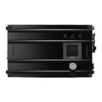
MOVIPRO PHE2 B-A15 Series
SEW-Eurodrive MOVIPRO PHE2 B-A15 Series Manuals
Manuals and User Guides for SEW-Eurodrive MOVIPRO PHE2 B-A15 Series. We have
1
SEW-Eurodrive MOVIPRO PHE2 B-A15 Series manual available for free PDF download: Operating Instructions Manual
SEW-Eurodrive MOVIPRO PHE2 B-A15 Series Operating Instructions Manual (116 pages)
Drive and Application Controller
Brand:
SEW-Eurodrive
| Category:
Controller
| Size: 5 MB
Table of Contents
Table of Contents
3
General Information
7
About this Documentation
7
Other Applicable Documentation
7
Structure of the Safety Notes
7
Meaning of Signal Words
7
Structure of Section-Related Safety Notes
8
Structure of Embedded Safety Notes
8
Decimal Separator in Numerical Values
8
Rights to Claim under Limited Warranty
9
Recycling, Reprocessing, Reuse
9
Product Names and Trademarks
9
Copyright Notice
9
Safety Notes
10
Preliminary Information
10
Duties of the User
10
Target Group
11
Designated Use
12
Restrictions under the European WEEE Directive 2012/19/EU
12
Restrictions of Use
12
Functional Safety Technology
13
Transport
14
Installation/Assembly
15
Electrical Installation
16
Required Preventive Measure
16
Protective Separation
16
Startup/Operation
17
Operating Switch
18
Functional Safety
19
Integrated Safety Technology
19
Safe State
19
Safety Concept
19
Safety Subfunctions
20
Limitations
22
Safety Requirements
23
Supports
23
Permitted Device Combinations
23
Installation Requirements
23
Requirements for the External Safety Controller
24
Startup Requirements
25
Requirements for Operation
25
Connection Variants
26
Basic Considerations
26
Connection of an External Safety Relay for STO with M12 Plug Connector
26
Device Structure
27
Type Designation
27
Scope of Delivery
27
Device Overview
28
Information on Switching Voltage
29
Nameplate
30
Designation Plates
31
Status and Error Code Plate
31
Warning Signs
31
Accessories
31
Available Accessories
31
Mechanical Installation
34
Requirements
34
Mounting Position
35
Minimum Clearance
35
Cooling
36
Installation
37
Fixed Angle Brackets
37
Tapped Holes on the Rear of the Device
37
Electrical Installation
39
Installation Notes
39
Motor Types
39
Low-Voltage Supply Systems
39
UL-Compliant Installation
40
Field Wiring) Power Terminals
40
Short Circuit Current Rating
40
Branch Circuit Protection
40
Motor Overload Protection
40
Environmental Rating
41
Wiring Diagrams
41
Electromagnetic Compatibility (EMC)
42
EMC Category
42
EMC-Compliant Installation
42
Cable Routing
42
Shielding
42
Protective Measures against Electrical Hazards
43
Connection Points for Mobile Applications
43
Installing Ground Connection or Equipotential Bonding
44
Using Prefabricated Cables
49
Use of Third-Party Cables
49
Line Components
49
Selecting the Residual Current Device
49
Selecting Line Fuses
50
Terminal Strips
51
Connection Site for Motor Connection
52
Connection of Signal Interfaces
52
Electrical Connections
54
Representation of Connections
54
Connection Cables
54
Cable Structure
55
X1261: AC 400 V Contact Conductor Connection
56
X1551: DC 24 V Connection for External Operating Switches
59
X2011: Motor with Brake Control
60
X2013: Motor with Brake Control
64
X4011: RS485 Interface - External
66
X4022: RS485 Interface - Service
67
6.11.10 X4441: M12 Parameter Memory
68
6.11.11 X5002_1: Digital Inputs/Outputs - Communication and Control Unit
69
6.11.12 X5002_2: Digital Input - Communication and Control Unit
69
6.11.13 X5002_3: Digital Input - Communication and Control Unit
70
6.11.14 X5002_4: Digital Input - Communication and Control Unit
70
6.11.15 X5003: Digital Input - Communication and Control Unit
71
6.11.16 X5502: Safe Disconnection - Input
72
Startup
74
For Your Safety
74
Requirements
75
Required Hardware
75
Required Software
75
Startup Note
75
Device Configuration
76
Software
76
Additional Information
76
Operation
77
For Your Safety
77
Relative Cyclic Duration Factor (Cdf)
78
Duty Cycles
78
Duty Type S1
78
Duty Type S2
79
Duty Type S3
79
Duty Types S4 to S10
79
Status and Fault Messages
80
Status Display of the Device
80
List of Faults
83
Status Leds
88
Fault Information
89
Fault Memory
90
Acknowledging Error Messages
90
Service
91
Inspection/Maintenance
91
Inspection & Maintenance
91
Device Replacement
91
Notes on Replacing Devices
91
Replacing the Device
91
Cleaning
92
Status Display
92
Fault Information
92
Electronics Service by SEW-EURODRIVE
92
Shutdown
93
Storage
93
Extended Storage
93
Waste Disposal
94
Technical Data
95
General
95
Current Reduction (Derating)
96
Input Data
97
Output Data
98
Safety-Related Characteristic Value STO
100
Motor Types
100
Marks
103
Basic Device
103
Dimension Drawings
104
Q8/0
104
Device with Motor Connection HAN 10E
106
Mounting Bracket
107
Index
108
Advertisement
Advertisement
Related Products
Sew Eurodrive MOVIPRO PHE10A 3 A-00 Series
SEW-Eurodrive MOVIPRO PHE10A-3 X A-00 Series
SEW-Eurodrive MOVIPRO PHE1 B-A15 Series
SEW-Eurodrive MOVIPRO PHE3 B-B15 Series
Sew Eurodrive MOVIPRO PHC11A-M1-2A-A1 Series
SEW-Eurodrive MOVIPRO PHC21A-A022M1-E45C-C5
SEW-Eurodrive MOVIPRO PHC21A-A075M1-E45C-C5
SEW-Eurodrive MOVIPRO PHC22A-A110M1-E45C-C5
SEW-Eurodrive MOVIPRO PHC22A-A150M1-E45C-C5
SEW-Eurodrive MOVIPRO PHC22A-A220M1-E45C-C5
SEW-Eurodrive Categories
DC Drives
Industrial Equipment
Controller
Inverter
Engine
More SEW-Eurodrive Manuals
Login
Sign In
OR
Sign in with Facebook
Sign in with Google
Upload manual
Upload from disk
Upload from URL