SEW-Eurodrive MOVIFIT FC Operating Instructions Manual
Decentralized drive control
Hide thumbs
Also See for MOVIFIT FC:
- Operating instructions manual (200 pages) ,
- Manual (178 pages) ,
- Manual (38 pages)

Related Manuals for SEW-Eurodrive MOVIFIT FC


Summary of Contents for SEW-Eurodrive MOVIFIT FC
- Page 1 *21316996_1214* Drive Technology \ Drive Automation \ System Integration \ Services Operating Instructions Decentralized Drive Control MOVIFIT ® Edition 12/2014 21316996/EN...
- Page 2 SEW-EURODRIVE—Driving the world...
-
Page 3: Table Of Contents
Contents Contents General information ........................6 How to use this documentation ..................6 Structure of the warning instructions ................6 Rights to claim under limited warranty ................8 Exclusion of liability ......................8 Other applicable documentation ..................8 Product names and trademarks ..................8 Copyright notice ...................... - Page 4 Contents Hybrid ABOX MTA...-S533-...-00/L10 ................85 5.10 Hybrid ABOX MTA...-S62.-...-00 .................. 89 5.11 Hybrid ABOX MTA...-I55.-...-00, MTA...-G55.-...-00 ............. 92 5.12 Hybrid ABOX MTA...-I65.-...-00, MTA...-G65.-...-00 ............. 95 5.13 Electrical connections ....................98 5.14 Encoder connection ....................112 5.15 Power bus connection examples ................114 5.16 Fieldbus systems connection examples ..............
- Page 5 Contents 9.14 Accessories ........................ 194 9.15 Dimension drawings ....................195 Declaration of Conformity ....................203 Address list ..........................206 Index ............................216 ® Operating Instructions – MOVIFIT...
-
Page 6: General Information
If you are unclear about any of the information in this documentation or require further informa- tion, please contact SEW-EURODRIVE. Structure of the warning instructions 1.2.1... - Page 7 General information Structure of the warning instructions Meaning of the hazard symbols The hazard symbols in the warning instructions have the following meaning: Hazard symbol Meaning General hazard Warning of dangerous electrical voltage Warning of hot surfaces Warning of risk of crushing Warning of suspended load Warning of automatic restart 1.2.3...
-
Page 8: Rights To Claim Under Limited Warranty
You must comply with the information contained in this documentation to ensure safe operation and to achieve the specified product characteristics and performance fea- tures. SEW-EURODRIVE assumes no liability for injury to persons or damage to equipment or property resulting from non-observance of these operating instructions. -
Page 9: Safety Notes
Safety notes Preliminary information Safety notes The following basic safety notes must be read carefully to prevent injury to persons and damage to property. The operator must ensure that the basic safety notes are read and observed. Ensure that persons responsible for the system and its operation, as well as persons who work independently on the unit, have read through the operat- ing instructions carefully and understood them. -
Page 10: Designated Use
Safety notes Designated use Designated use ® MOVIFIT is a component intended for installation in electrical systems or machines. In case of installation in machines, startup of MOVIFIT ® units (i.e. start of designated operation) is prohibited until it is determined that the machine meets the requirements stipulated in the Machinery Directive 2006/42/EC. -
Page 11: Installation
Safety notes Installation Installation The units must be installed and cooled according to the regulations and specifications in the corresponding documentation. ® Protect MOVIFIT from excessive strain. The following applications are prohibited unless explicitly permitted: • Use in potentially explosive atmospheres. •... -
Page 12: Operation
Safety notes Operation Operation ® Systems in which MOVIFIT is installed must, if necessary, be equipped with addition- al monitoring and protection devices according to applicable safety regulations; e.g., the German law governing technical equipment (Gesetz über technische Arbeitsmit- tel), accident prevention regulations, etc. Additional protective measures may be nec- ®... -
Page 13: Unit Structure
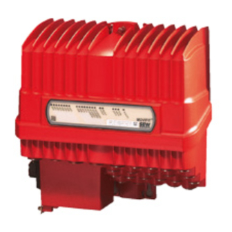
Unit structure MOVIFIT® FC Unit structure MOVIFIT® MOVIFIT ® MOVIFIT ® FC is a decentralized drive controller with integrated frequency inverter that controls a maximum of up to two gearmotors. The following figure shows a MOVIFIT ® FC unit in size 1 in standard design: 4285969931 [1] EBOX (active electronics unit) [2] ABOX (passive connection unit) -
Page 14: Overview - Connection Configuration
Unit structure Overview – Connection configuration Overview – Connection configuration ® The following figures show the MOVIFIT FC designs that are described in these oper- ating instructions: EBOX ABOX Design MTA...-S02.-...-00 Standard ABOXwith terminals and cable bushings MTA...-S42.-...-00 MTF...-...-00 Hybrid ABOX with M12 for I/Os MTA...-S52.-...-00 Size 1... - Page 15 Unit structure Overview – Connection configuration Designs with circular connector (Intercontec) for connecting the motor: EBOX ABOX Design MTA...-I55.-...-00 Hybrid ABOX with 1 round connector (Intercontec), 1 x downward motor output, and M12 for I/Os and bus MTA...-G55.-...-00 MTF...-...-00 Hybrid ABOX with 1 circular connector (Intercontec), 1 x motor out- Size 1 put at front, and M12 for I/Os and bus...
-
Page 16: Ebox (Active Electronics Unit)
Unit structure EBOX (active electronics unit) EBOX (active electronics unit) ® The MOVIFIT FC EBOX is a closed electronics unit with a communication interface, digital inputs/outputs (I/Os) and a frequency inverter: EBOX " MTF...-..-00" 1 2 3 4 5 6 1 2 3 4 18014399322004747 [A] Size 1... -
Page 17: Abox (Passive Connection Unit)
Unit structure ABOX (passive connection unit) ABOX (passive connection unit) ® The following figure depicts examples of the MOVIFIT ABOX: ABOX " MTA...-..-00" I O N [10] [11] [13] [12] 18014399322006411 Mounting rail Connection to EBOX Nameplate of complete unit Inner nameplate of the ABOX Protection cover DIP switch S2 for bus address (PROFIBUS and DeviceNet™... -
Page 18: Hygienic Plus Design (Optional)
Unit structure Hygienicplus variant (optional) Hygienicplu s variant (optional) Hygienic plus design (optional) 3.5.1 Properties plus The Hygienic design has the following characteristics: • IP66 in accordance with EN 60529 and IP69K in accordance with DIN 40050-9 (MOVIFIT ® housing closed and all cable bushings sealed according to the relevant degree of protection) •... - Page 19 Unit structure Hygienicplus variant (optional) ® The following figure depicts the additional features of MOVIFIT units in the optional Hygienic plus design: EBOX " MTF12...-..-00" ABOX "MTA12...-S02.-...-00" [10] [11] 9007200067232139 EBOX with special surface treatment (available only in one color) Signal plug connector with gasket Gasket between ABOX and cover plate Power plug connector with gasket...
-
Page 20: Movifit ® With L10 Profinet Interface Scrj/Pof
Unit structure MOVIFIT® with L10 PROFINET interface SCRJ/POF MOVIFIT® with L10 PROFINET interface SCRJ/POF MOVIFIT ® with L10 PROFINET interface SCRJ/POF 3.6.1 Unit structure ® The following figure shows MOVIFIT with the L10 PROFINET interface SCRJ/POF (POF option L10): 9007202682186763 [1] MOVIFIT ®... -
Page 21: Movifit Fc Type Designation
Unit structure MOVIFIT® FC type designation MOVIFIT® FC type designation MOVIFIT ® FC type designation 3.7.1 EBOX EBOX nameplates EBOX unit identification ® The following figure shows an example of the EBOX unit identification of MOVIFIT FC/Class/1,5 kW/-------/--- 13324613771 Outer nameplate EBOX The following figure shows an example of an outer nameplate of the EBOX of MOVIFIT ®... - Page 22 Unit structure MOVIFIT® FC type designation EBOX type designation ® The following table shows an example of the type designation of the MOVIFIT MTF11A015-503-P10A -00/S11 EBOX: ® Unit series MT = MOVIFIT ® Unit type F = MOVIFIT FC (frequency inverters) Series 11 = Standard (IP65) 12 = Hygienic...
- Page 23 Unit structure MOVIFIT® FC type designation EBOX design 01 = DAS motor 400 V, 50 Hz 10 = DRS.. motor 400 V, 50 Hz 11 = DRE.. motor 400 V, 50 Hz 12 = DRS.. motor 460 V, 60 Hz 13 = DRE..
- Page 24 Unit structure MOVIFIT® FC type designation 3.7.2 ABOX ABOX nameplates ABOX unit identification The following figure shows an example of the ABOX unit identification of MOVIFIT ® MTA11A-503-S021-D01-00 MAC-ID: FF–FF–FF–FF–FF–FF 13458059019 [1] ABOX type designation [2] MAC ID of the fieldbus interface Outer nameplate ABOX The following figure shows an example of an outer nameplate of the ABOX of MOVIFIT...
- Page 25 Unit structure MOVIFIT® FC type designation Nameplate of the complete unit The following figure provides an example of a nameplate of the complete MOVIFIT ® FC unit (EBOX and ABOX): SO#: 01.1785033001.0001.12 Type: MTF11A015-503-P10A-11 MTA11A-503-S021-D01-00 MOVIFIT ® ML01 LISTED IND. CONT. EQ.2D06 N2936 9007206145755019 This nameplate is only available if the EBOX and the ABOX have been ordered as...
- Page 26 Unit structure MOVIFIT® FC type designation ABOX type designation ® The following table shows an example of the type designation of the MOVIFIT MTA11A-503-S021-D01-00/BW1/M11 ABOX: ® Unit series MT = MOVIFIT Unit type A = ABOX (connection box) Series 11 = Standard (IP65) 12 = Hygienic plus (IP69K)
- Page 27 Unit structure MOVIFIT® FC type designation ABOX option 2 00S = Plug connector STO M11 = Stainless steel mounting rail M1S = Stainless steel mounting rail and plug connector STO M2A = Corrosion-resistant mounting rail M2S = Corrosion-resistant mounting rail and plug connector STO L10 = PROFINET interface SCRJ/POF (POF option L10) 1) POF option L10 is only available in combination with S53 connection configuration and vice versa.
-
Page 28: Mechanical Installation
Mechanical installation General information Mechanical installation General information CAUTION Risk of injury due to protruding parts, especially the mounting rail. Risk of cutting or crushing. • Cover sharp and protruding parts, especially the mounting rail, to protect against injury and damage. •... -
Page 29: Permitted Mounting Position
Mechanical installation Permitted mounting position Permitted mounting position ® MOVIFIT is mounted by means of a mounting plate using the 4 screws already instal- led in the mounting surface. For detailed information, refer to chapter "Mount- ing" (→ 2 30). The following figure depicts the approved mounting positions for MOVIFIT ®... -
Page 30: Installation
Mechanical installation Installation Installation 4.4.1 Mounting rail ® MOVIFIT is equipped with a mounting rail to attach the unit to a level, low-vibration mounting surface using M6 screws. For bore dimensions of the respective type of fix- ture, see the following figures. Drilling template for standard mounting rail 7.0 (6x) 13.9 (6x) - Page 31 Mechanical installation Installation For detailed dimension drawings, refer to chapter "Technical data" > "Dimension draw- ings". ® Operating Instructions – MOVIFIT...
- Page 32 Mechanical installation Installation Drilling template for optional mounting rail /M11 7.0 (8x) 13.9 (8x) min. 50 334.4 18014399308791819 • [1] Observe the minimum installation clearance so that the EBOX can be removed from the ABOX. • [2] Observe the minimum installation clearance required to operate the mainte- nance switch and to ensure heat dissipation for the unit.
- Page 33 Mechanical installation Installation Drilling template for mounting rail (POF option L10) ® The MOVIFIT unit with the special mounting rail is mounted in the same way as a unit with /M11 mounting rail. For the special mounting rail, an additional retaining screw is required behind the POF option, see the figure below.
- Page 34 Mechanical installation Installation 4.4.2 Fastening CAUTION Risk of crushing if the load falls. Severe or fatal injuries. • Do not stand under the load. • Secure the danger zone. CAUTION Risk of injury due to protruding parts. Risk of cutting or crushing. •...
- Page 35 Mechanical installation Installation 3. Attach the ABOX with mounting plate to the screws. 9007200013306891 4. Tighten the screws. CAUTION! Risk of injury if the load falls. Minor injuries. • Tighten at least 4 wall screws to ensure a secure fit after mounting. 9007200013331723 ®...
-
Page 36: Central Opening/Closing Mechanism
Mechanical installation Central opening/closing mechanism Central opening/closing mechanism WARNING Risk of burns due to hot surfaces of the MOVIFIT ® unit. Serious injuries. • Do not touch the MOVIFIT ® unit until it has cooled down sufficiently. CAUTION Risk of injury if the EBOX falls. Minor injuries. - Page 37 Mechanical installation Central opening/closing mechanism 2. Remove the EBOX from the ABOX by lifting it upwards. Do not jam the EBOX dur- ing this procedure. EBOX 90° ABOX 813353099 4.5.2 Closing You need a socket wrench (SW8) for the central retaining screw. 1.
- Page 38 Mechanical installation Central opening/closing mechanism 3. Check the EBOX for correct position. NOTICE The central opening/closing mechanism may be damaged as a result. Destruction of central opening/closing mechanism. • Carefully close the EBOX manually if it is in a tilted mounting position. •...
-
Page 39: Tightening Torques
Mechanical installation Tightening torques Tightening torques 4.6.1 Blanking plugs Tighten the blanking plugs included in the delivery with 2.5 Nm: 758614667 ® Operating Instructions – MOVIFIT... - Page 40 Mechanical installation Tightening torques 4.6.2 EMC cable glands Tighten the EMC cable glands optionally supplied by SEW‑EURODRIVE to the fol- lowing torques: 758624523 Screw fitting Part number Size Tightening torque EMC cable glands (nickel-plat- 18204783 M16 x 1.5 3.5 Nm to 4.5 Nm ed brass) 18204791 M20 x 1.5...
-
Page 41: Movifit ® Hygienic Plus Design
Mechanical installation MOVIFIT® Hygienic plus design MOVIFIT® Hygienic plus design MOVIFIT ® Hygienic plus design INFORMATION SEW‑EURODRIVE guarantees that the Hygienic plus special surface treatment is free from faults when delivered. Transport damages must be reported immediately upon receipt of the unit. Although the housing surfaces have a high impact resistance, they are to be handled with care. - Page 42 Mechanical installation MOVIFIT® Hygienic plus design plus 4.7.2 Tightening torques for Hygienic design NOTICE Loss of warranted IP69K degree of protection if the screw plugs are installed incor- rectly or not at all. Damage to the MOVIFIT ® unit. • IP69K degree of protection is only possible for MOVIFIT ®...
- Page 43 Mechanical installation MOVIFIT® Hygienic plus design EMC cable glands Tighten the EMC cable glands optionally supplied by SEW‑EURODRIVE to the fol- lowing torques: 512772875 Screw fitting Part number Size Tightening torque EMC cable glands (nickel-plat- 18204783 M16 x 1.5 3.0 Nm to 4.0 Nm ed brass) 18204791 M20 x 1.5...
-
Page 44: Electrical Installation
Electrical installation General information Electrical installation General information Observe the following notes on electrical installation: • Observe the general safety notes. • Strictly observe all instructions referring to the technical data and the permissible conditions regarding the place of installation. •... - Page 45 Electrical installation Installation planning taking EMC aspects into account 5.2.1 Equipotential bonding Regardless of the PE connection, it is essential that low-impedance, HF-capable equipotential bonding is provided (see also EN 60204-1 or DIN VDE 0100-540): • Establish a connection over a wide surface area between the MOVIFIT ®...
-
Page 46: Installation Instructions (All Versions)
Electrical installation Installation instructions (all versions) Installation instructions (all versions) 5.3.1 Connecting supply system leads • The nominal voltage and frequency of the MOVIFIT ® unit must correspond to the data of the supplying system. • Size the cable cross section according to the input current I for rated power (see line "Technical data"... - Page 47 Electrical installation Installation instructions (all versions) 5.3.4 Notes on PE connection and/or equipotential bonding WARNING Electric shock due to incorrect connection of PE. Severe, fatal injuries. • The permitted tightening torque for the screw is 2.0 – 2.4 Nm (18 – 21 lb.in) •...
- Page 48 Electrical installation Installation instructions (all versions) 5.3.5 Definition PE, FE WARNING Electric shock due to incorrect connection of PE to the terminals marked with "FE" (functional earth). The FE connections are not designed for this purpose. This means electrical safety is not guaranteed. Severe or fatal injuries.
- Page 49 Electrical installation Installation instructions (all versions) 24V_S = Actuator supply The 24V_S voltage level supplies: • The digital outputs DO.. , • The connected actuators • The VO24_IV sensor supply output. The digital inputs DI12 – DI15 are connected to the reference potential 0V24_S as these can be connected to the same connections as an alternative to the outputs.
- Page 50 Electrical installation Installation instructions (all versions) 24V_O = Option supply The 24V_O voltage level supplies: • the integrated option card S11, S12A or S12B • and the sensor/actuator interfaces on the S11 option card. With PROFIsafe option S11 and safety option S12, the complete safety electronics and the safe inputs/outputs are supplied from 24V_O.
- Page 51 Electrical installation Installation instructions (all versions) 5.3.7 Dimensioning the 24 V voltage supply This chapter describes the dimensioning of the DC 24 V supply. The following table gives an overview of the current consumption and power demand of the DC 24 components of MOVIFIT ®...
- Page 52 Electrical installation Installation instructions (all versions) Example 1 MOVIFIT ® FC with: • "Classic" function level • PROFIBUS interface Type designation EBOX: MTF11A015-503-P10A-15 ABOX: MTA11A-503-S023-D01-00/BW1 Connected components The following components are connected to the MOVIFIT ® unit: • 6 sensors with 50 mA (1.2 W) respectively •...
- Page 53 Electrical installation Installation instructions (all versions) Example 2 MOVIFIT ® FC with: • "Technology" function level • PROFINET IO interface • POF option L10 • S12A safety option Type designation EBOX: MTF11A015-503-E21A-15/S12A ABOX: MTA11A-503-S533-D01-00/BW1/L10 Connected components The following components are connected to the MOVIFIT ®...
- Page 54 Electrical installation Installation instructions (all versions) 5.3.8 Plug connectors All MOVIFIT ® plug connectors are illustrated in these operating instructions with view on the contact end. 5.3.9 Operating braking resistors Braking resistors dissipate the energy generated during braking operations and get hot in the process.
- Page 55 Electrical installation Installation instructions (all versions) 5.3.13 UL-compliant installation INFORMATION Due to UL requirements, the following chapter is always printed in English independ- ent of the language of the publication. Field wiring power terminals Observe the following notes for UL-compliant installation: •...
- Page 56 Electrical installation Installation instructions (all versions) Ambient temperature ® MOVIFIT FC (except model rated 4 kW) is suitable for an ambient temperature of 40 °C, max. 60 °C with derated output current. To determine the output current rating at higher than 40 °C, the output current should be derated 3.0% per °C between 40 °C and 60 °C.
-
Page 57: Additional Installation Instructions For Group Drives
Electrical installation Additional installation instructions for group drives Additional installation instructions for group drives ® The following figure shows the prescribed installation for group drives with MOVIFIT ® MOVIFIT 1240954123 When installing such group drives, also follow the installation instructions below: •... -
Page 58: Installation Topology (Example)
Electrical installation Installation topology (example) Installation topology (example) ® The following figure shows the general installation topology of MOVIFIT 400 V 24 V 24 V 400 V ® ® MOVIFIT MOVIFIT DR.. DR.. 5068774155 ® Operating Instructions – MOVIFIT... -
Page 59: Standard Abox Mta
Electrical installation Standard ABOX MTA...-S02.-...-00 Standard ABOX MTA...-S02.-...-00 5.6.1 Description The following figure depicts the standard ABOX with terminals and cable bushings: 9007200067288715 [1] Maintenance switch (optional) [2] PE connection [3] Diagnostics socket (RJ10) under the screw plug ® Operating Instructions – MOVIFIT... - Page 60 Electrical installation Standard ABOX MTA...-S02.-...-00 5.6.2 Variants The following variants of the standard ABOX are available for MOVIFIT ® FC (MTF): • MTA11A-503-S02.-...-00: – Optional internal or external braking resistor – Optional load break switch – Optional load break switch and line protection The following figure shows the screw connections and plug connectors of the standard ABOX depending on the fieldbus interface: PROFIBUS...
- Page 61 Electrical installation Standard ABOX MTA...-S02.-...-00 5.6.3 Additional installation instructions for MTA...-S02.-...-00 Permitted connection cross-section and current carrying capacity of the terminals Terminal data X1, X20 X8, X9 X25, X30, X31, X35, X45, X81, X91 Connection cross 0.2 – 6 mm 0.08 –...
- Page 62 Electrical installation Standard ABOX MTA...-S02.-...-00 Actuating the terminals Terminals X1, X20 Connecting conductors without screw- Connecting conductors with screw- driver driver 812406283 812407947 1) Single-wire conductors and flexible conductors with conductor end sleeves can be installed directly (without using a tool) up to 2 cross section sizes below the rated cross section. 2) Untreated, flexible conductors or conductors with small cross sections cannot be directly inserted into the terminal.To open the clamping spring when you want to connect such conductors, push a screwdriver firmly into the actuation opening.
- Page 63 Electrical installation Standard ABOX MTA...-S02.-...-00 Connection of the PROFIBUS cable in MOVIFIT ® Observe the following guidelines of the PROFIBUS user organization (Internet: www.profibus.com) for your PROFIBUS installation: • "Installation guidelines for PROFIBUS DP/FMS", order number 2.111 (German) or 2.112 (English) •...
- Page 64 Electrical installation Standard ABOX MTA...-S02.-...-00 Connecting the hybrid cables • SEW‑EURODRIVE recommends using the shielded and prefabricated SEW hybrid ® cables specifically designed for connecting MOVIFIT to the motor. See chapter "Electrical Installation" > "Hybrid cables". • The outer shield of the hybrid cable must be attached to the housing of the unit us- ing a suitable EMC cable gland.
- Page 65 Electrical installation Standard ABOX MTA...-S02.-...-00 5.6.4 Terminal positions The following figure shows the position of the terminals in the ABOX: 1 2 3 4 5 6 7 8 2 3 4 [5] X30 (X31) 2 3 4 [6] X35 [7] X50 [12] [11] [10]...
- Page 66 Electrical installation Standard ABOX MTA...-S02.-...-00 5.6.5 Terminal assignment WARNING Electric shock due to dangerous voltages in the ABOX. The maintenance switch disconnects only the integrated frequency inverter from the power supply. Voltage is still present on the terminals of the MOVIFIT ®...
- Page 67 Electrical installation Standard ABOX MTA...-S02.-...-00 X20: 24 V supply terminal (24 V power bus) 2 3 4 5 6 11 11 12 12 13 13 14 1415 15 16 1718 2 3 4 1 2 3 4 11 12 13 14 1 2 3 4 5 1 2 3 4 5 6 7 8 12 13 14 15...
- Page 68 Electrical installation Standard ABOX MTA...-S02.-...-00 X8, X81, X9 and X91: Motor connection terminals WARNING Risk of crushing due to incorrect parameterization of the digital output DB00. Severe or fatal injuries. • If digital output DB00 is used to control the brake, do not change the parameters that define the functions of the digital output.
- Page 69 Electrical installation Standard ABOX MTA...-S02.-...-00 X29: 24 V distributor terminals WARNING Danger through unexpected unit behavior. When you use terminals X29/5, X29/6, X29/15, and X29/16 for a safe disconnection, you must observe the SEW manual "MOVIFIT ® MC/FC – Functional Safety". Severe or fatal injuries.
- Page 70 Electrical installation Standard ABOX MTA...-S02.-...-00 X25: I/O terminals 2 3 4 5 6 11 11 12 12 13 13 14 1415 15 16 1718 2 3 4 1 2 3 4 11 12 13 14 1 2 3 4 5 1 2 3 4 5 6 7 8 12 13 14 15 12 13 14 1516 17 18...
- Page 71 Electrical installation Standard ABOX MTA...-S02.-...-00 2 3 4 5 6 11 11 12 12 13 13 14 1415 15 16 1718 2 3 4 1 2 3 4 11 12 13 14 1 2 3 4 5 1 2 3 4 5 6 7 8 12 13 14 15 12 13 14 1516 17 18 2 3 4...
- Page 72 Electrical installation Standard ABOX MTA...-S02.-...-00 X35: SBus terminals 2 3 4 5 6 11 11 12 12 13 13 14 1415 15 16 1718 2 3 4 1 2 3 4 11 12 13 14 1 2 3 4 5 1 2 3 4 5 6 7 8 12 13 14 15 12 13 14 1516 17 18...
- Page 73 Electrical installation Standard ABOX MTA...-S02.-...-00 X45: I/O terminals for PROFIsafe option S11 (only in connection with PROFIsafe option card S11) WARNING Danger through unexpected unit behavior. When you are using terminals X45 for safe disconnection, you must observe the "MOVIFIT ®...
- Page 74 Electrical installation Standard ABOX MTA...-S02.-...-00 X45: I/O terminals for safety option S12A (only in connection with safety option card S12A) WARNING Danger through unexpected unit behavior. When you are using terminals X45 for safe disconnection, you must observe the "MOVIFIT ®...
- Page 75 Electrical installation Standard ABOX MTA...-S02.-...-00 X45: I/O terminals for safety option S12B (only in connection with safety option card S12B) WARNING Danger through unexpected unit behavior. When you are using terminals X45 for safe disconnection, you must observe the "MOVIFIT ®...
- Page 76 Electrical installation Standard ABOX MTA...-S02.-...-00 X30 and X31: PROFIBUS terminals (only with PROFIBUS designs) 1 2 3 2 3 4 5 6 11 11 12 12 13 13 14 1415 15 16 1718 2 3 4 1 2 3 4 11 12 13 14 1 2 3 4 5 1 2 3 4 5 6 7 8...
- Page 77 Electrical installation Standard ABOX MTA...-S02.-...-00 X30 and X31: Ethernet plug connector (only with PROFINET IO, EtherNet/IP™ or Modbus/TCP designs) 2 3 4 5 6 11 11 12 12 13 13 14 1415 15 16 1718 2 3 4 1 2 3 4 11 12 13 14 1 2 3 4 5 1 2 3 4 5 6 7 8...
- Page 78 Electrical installation Standard ABOX MTA...-S02.-...-00 X11, X30: DeviceNet™ plug connectors / terminals (only with DeviceNet™ designs) 2 3 4 5 6 11 11 12 12 13 13 14 1415 15 16 1718 1 2 3 4 5 2 3 4 1 2 3 4 11 12 13 14 1 2 3 4 5...
-
Page 79: Hybrid Abox Mta
Electrical installation Hybrid ABOX MTA...-S42.-...-00 Hybrid ABOX MTA...-S42.-...-00 INFORMATION • The hybrid ABOX is based on the standard ABOX MTA...-S02.-...-00. The follow- ing therefore only describes the additional plug connectors in comparison with the standard ABOX. • For a description of the terminals, refer to chapter "Standard ABOX MTA...- S02.-...-00. - Page 80 Electrical installation Hybrid ABOX MTA...-S42.-...-00 5.7.2 Variants The following variants of the hybrid ABOX are available for MOVIFIT ® FC (MTF): • MTA11A-503-S42.-...-00: – Optional internal or external braking resistor – Optional load break switch – Optional load break switch and line protection The following figure shows the cable glands and plug connectors of the hybrid ABOX: MTA11A-503-S421-...-00 PROFIBUS...
- Page 81 Electrical installation Hybrid ABOX MTA...-S42.-...-00 5.7.3 Plug connector positions The following figure shows the plug connectors of the hybrid ABOX: [1] X21 – X24 [1] X25 – X28 [2] X50 3570049547 [1] X21 – X28 Digital inputs/outputs (M12, 5-pole, female, A-coded) [2] X50 Diagnostic interface (RJ10, female, under the screw...
-
Page 82: Hybrid Abox Mta
Electrical installation Hybrid ABOX MTA...-S52.-...-00 Hybrid ABOX MTA...-S52.-...-00 INFORMATION • The hybrid ABOX is based on the standard ABOX MTA...-S02.-...-00. The follow- ing therefore only describes the additional plug connectors in comparison with the standard ABOX. • For a description of the terminals, refer to chapter "Standard ABOX MTA...- S02.-...-00 (→... - Page 83 Electrical installation Hybrid ABOX MTA...-S52.-...-00 5.8.2 Variants The following variants of the hybrid ABOX are available for MOVIFIT ® FC (MTF): • MTA11A-503-S52.-...-00: – Optional internal or external braking resistor – Optional load break switch – Optional load break switch and line protection The following figure shows the cable glands and plug connectors of the Hybrid ABOX depending on the fieldbus interface: M12, B-codiert,...
- Page 84 Electrical installation Hybrid ABOX MTA...-S52.-...-00 5.8.3 Plug connector positions The following figure shows the plug connectors of the hybrid ABOX: PROFIBUS: [1] X11 [2] X12 Ethernet: [3] X11 [4] X12 DeviceNet™: [5] X11 [6] X21 – X24 [6] X25 – X28 [7] X50 9007202824943627 [1] X11...
-
Page 85: Hybrid Abox Mta
Electrical installation Hybrid ABOX MTA...-S533-...-00/L10 Hybrid ABOX MTA...-S533-...-00/L10 INFORMATION • The hybrid ABOX is based on the standard ABOX MTA...-S02.-...-00. The follow- ing therefore only describes the additional plug connectors in comparison with the standard ABOX. • For a description of the terminals, refer to chapter "Standard ABOX MTA...- S02.-...-00 (→... - Page 86 Electrical installation Hybrid ABOX MTA...-S533-...-00/L10 The following figure shows the mounting rail and POF option L10 from the back: 5057677451 [1] DC 24 V supply Cable gland (connected at the factory) [2] PROFINET IO, port 1 Cable gland (connected at the factory) [3] PROFINET IO, port 2 Cable gland (connected at the factory) [4] POF option L10...
- Page 87 Electrical installation Hybrid ABOX MTA...-S533-...-00/L10 5.9.2 Variants The following variants of the hybrid ABOX are available for MOVIFIT ® FC (MTF): • MTA11A-503-S53.-..-00/L10: – Optional internal or external braking resistor – Optional load break switch – Optional load break switch and line protection The following figure shows the cable glands and plug connectors of the hybrid ABOX with POF option L10: PROFINET IO MTA11A-503-S533-...-00/L10...
- Page 88 Electrical installation Hybrid ABOX MTA...-S533-...-00/L10 5.9.3 Plug connector positions The following figure shows the plug connectors of MOVIFIT ® with POF option L10: MTA11A-503-S533-...-../L10 [2] [3] [5] [6] 5048967563 [1] X11 PROFINET IO interface, port 1 M12, D coding, female (plugged at the factory) [2] X12 PROFINET IO interface, port 2...
-
Page 89: Hybrid Abox Mta
Electrical installation Hybrid ABOX MTA...-S62.-...-00 5.10 Hybrid ABOX MTA...-S62.-...-00 INFORMATION • The hybrid ABOX is based on the standard ABOX MTA...-S02.-...-00. The follow- ing therefore only describes the additional plug connectors in comparison with the standard ABOX. • For a description of the terminals, refer to chapter "Standard ABOX MTA...- S02.-...-00 (→... - Page 90 Electrical installation Hybrid ABOX MTA...-S62.-...-00 5.10.2 Variants The following variants of the hybrid ABOX are available for MOVIFIT ® FC (MTF): • MTA11A-503-S62.-...-00: – Optional internal or external braking resistor – Optional load break switch – Optional load break switch and line protection The following figure shows the cable glands and plug connectors of the hybrid ABOX: PROFINET IO MTA11A-503-S623-...-00...
- Page 91 Electrical installation Hybrid ABOX MTA...-S62.-...-00 5.10.3 Plug connector positions NOTICE The RJ45 socket can be damaged by inserting commercially available RJ45 patch cables without push-pull connector housing. Damage to the RJ45 socket. • Only plug suitable push-pull RJ45 mating connectors according to IEC PAS 61076-3-117 into push-pull RJ45 sockets.
-
Page 92: Hybrid Abox Mta
Electrical installation Hybrid ABOX MTA...-I55.-...-00, MTA...-G55.-...-00 5.11 Hybrid ABOX MTA...-I55.-...-00, MTA...-G55.-...-00 INFORMATION • The hybrid ABOX is based on the standard ABOX MTA...-S02.-...-00. The follow- ing therefore only describes the additional plug connectors in comparison with the standard ABOX. • For a description of the terminals, refer to chapter "Standard ABOX MTA...- S02.-...-00 (→... - Page 93 Electrical installation Hybrid ABOX MTA...-I55.-...-00, MTA...-G55.-...-00 5.11.2 Variants The following variants of the hybrid ABOX are available for MOVIFIT ® FC (MTF): • MTA11A-503-I55.-...-00/MTA11A-503-G55.-...-00 – Optional internal or external braking resistor – Optional load break switch – Optional load break switch and line protection The following figure shows the cable glands and plug connectors of the Hybrid ABOX depending on the fieldbus interface: MTA11A-503-I551-...-00...
- Page 94 Electrical installation Hybrid ABOX MTA...-I55.-...-00, MTA...-G55.-...-00 5.11.3 Plug connector positions The following figure shows the plug connectors of the hybrid ABOX: PROFIBUS: [1] X11 [2] X12 Ethernet: [3] X11 [4] X12 DeviceNet™: [5] X11 MTA11A-503-G55.-...-00: [6] X80 MTA11A-503-I55.-...-00: [6] X80 [7] X21 –...
-
Page 95: Hybrid Abox Mta
Electrical installation Hybrid ABOX MTA...-I65.-...-00, MTA...-G65.-...-00 5.12 Hybrid ABOX MTA...-I65.-...-00, MTA...-G65.-...-00 INFORMATION • The hybrid ABOX is based on the standard ABOX MTA...-S02.-...-00. The follow- ing therefore only describes the additional plug connectors in comparison with the standard ABOX. • For a description of the terminals, refer to chapter "Standard ABOX MTA...- S02.-...-00 (→... - Page 96 Electrical installation Hybrid ABOX MTA...-I65.-...-00, MTA...-G65.-...-00 5.12.2 Variants The following variants of the hybrid ABOX are available for MOVIFIT ® FC (MTF): • MTA11A-503-I65.-...-00/MTA11A-503-G65.-...-00: – Optional internal or external braking resistor – Optional load break switch – Optional load break switch and line protection The following figure shows the cable glands and plug connectors of the hybrid ABOX: PROFINET IO MTA11A-503-I653-...-00...
- Page 97 Electrical installation Hybrid ABOX MTA...-I65.-...-00, MTA...-G65.-...-00 5.12.3 Plug connector positions NOTICE The RJ45 socket can be damaged by inserting commercially available RJ45 patch cables without push-pull connector housing. Damage to the RJ45 socket. • Only plug suitable push-pull RJ45 mating connectors according IEC 61076‑3‑117 into push-pull RJ45 sockets.
-
Page 98: Electrical Connections
Electrical installation Electrical connections 5.13 Electrical connections 5.13.1 Connection cables Connection cables are not included in the delivery. Prefabricated cables for connection between SEW components can be ordered from SEW‑EURODRIVE at any time. These cables are described in the following sections. Specify the part number and length of the required cable in your order. - Page 99 Electrical installation Electrical connections 5.13.2 X80, X90: Motor connection The following table shows information about this connection: Function Motor connection Connection type Intercontec 723 H-Tec, 7 + 3-pole, female (downward or to the front) Wiring diagram 4312557451 Assignment Name Function PE connection Motor phase U output Motor phase V output...
- Page 100 Electrical installation Electrical connections 5.13.3 X21 – X28: Digital inputs/outputs Variants The number and assignments of the digital inputs/outputs depends on the function lev- el and the fieldbus interface if the MOVIFIT ® unit. I/O variant MOVIFIT ® design Function level Fieldbus 4 DI None...
- Page 101 Electrical installation Electrical connections VO24-I VO24-I VO24-II VO24-II res. res. res. res. 0V24_C 0V24_C 0V24_C 0V24_C DI00 DI01 DI02 DI03 n.c. n.c. n.c. n.c. 6 DI + 2 DI/O VO24-III VO24-III VO24-IV VO24-IV res. res. res. res. 0V24_C 0V24_C 0V24_S 0V24_S DI04 DI05...
- Page 102 Electrical installation Electrical connections Y adapter For connecting 2 sensors/actuators to an M12 plug connector, use a Y adapter with extension. The Y adapter is available from different manufacturers: Manufac- Escha turer: Type: WAS4-0,3-2FKM3/.. 915294347 Manufac- Binder turer: Type: 79 5200 .. 1180380683 Manufac- Phoenix Contact...
- Page 103 Electrical installation Electrical connections 5.13.4 X70F: STO (optional) WARNING No safety-related disconnection of the MOVIFIT ® drive. Severe or fatal injuries. • Do not use the 24 V output (pins 1 and 2) for safety-related applications with MOVIFIT ® drives. ®...
- Page 104 Electrical installation Electrical connections STO jumper plug WARNING Safety-related disconnection of the MOVIFIT ® drive is not possible when the STO jumper plug is used. Severe or fatal injuries. • You may only use the STO jumper plug when the MOVIFIT ®...
- Page 105 Electrical installation Electrical connections 5.13.5 X11: PROFIBUS input The following table shows information about this connection: Function PROFIBUS input Connection type (M12, 5-pole, male, B-coded) Wiring diagram Assignment Name Function res. Reserved A_IN PROFIBUS data line A res. Reserved B_IN PROFIBUS data line B res.
- Page 106 Electrical installation Electrical connections 5.13.6 X12: PROFIBUS output The following table shows information about this connection: Function PROFIBUS output Connection type (M12, 5-pole, female, B-coded) Wiring diagram 9007201609172107 Assignment Name Function +5 V DC 5 V output A_OUT PROFIBUS data line A 0V5 reference potential B_OUT PROFIBUS data line B...
- Page 107 Electrical installation Electrical connections 5.13.7 X11: DeviceNet™ interface The following table shows information about this connection: Function DeviceNet™ interface Connection type (Micro-style connector, male, A‑coded) Wiring diagram 9007201519559179 Assignment Name Function Drain Shield/equipotential bonding DC 24 V input Reference potential CAN_H CAN data line (high) CAN_L...
- Page 108 Electrical installation Electrical connections 5.13.8 X11, X12: Ethernet interface The following table shows information about this connection: Function • PROFINET IO interface • EtherNet/IP™ interface • Modbus/TCP interface Connection type M12, 4-pole, female, D-coded Wiring diagram 9007201719341963 Assignment Name Function Transmit line (+) Receive line (+) Transmit line (-)
- Page 109 Electrical installation Electrical connections 5.13.9 X11, X12: Ethernet interface The following table shows information about this connection: Function • PROFINET IO interface • EtherNet/IP™ interface • Modbus/TCP interface Connection type Push-pull RJ45 Wiring diagram 9007201609174667 Assignment Name Function Transmit line (+) Transmit line (-) Receive line (+) res.
- Page 110 Electrical installation Electrical connections Closing plug, optional NOTICE Loss of warranted degree of protection if the closing plugs are installed incorrectly or not at all. Damage to the MOVIFIT ® unit. • If an RJ45 socket is not occupied by a connector, you must seal it with the follow- ing closing plug.
- Page 111 Electrical installation Electrical connections 5.13.10 X30, X31: PROFINET POF interface The following table shows information about this connection: Function PROFINET interface SCRJ / POF (at POF option L10) Connection type Push-pull SCRJ Wiring diagram Assignment Name Function Transmit line (POF) Receive line (POF) 5.13.11 X13: DC 24 V supply The following table shows information about this connection:...
-
Page 112: Encoder Connection
Electrical installation Encoder connection 5.14 Encoder connection 5.14.1 EI7. incremental encoder Properties The EI7. incremental encoder offers the following features: • HTL or sin/cos interface (MOVIFIT ® does not evaluate sin/cos signals) EI71: 1 pulse/revolution => 4 increments/revolution EI72: 2 pulses/revolution =>... - Page 113 Electrical installation Encoder connection Connection via terminals ® MOVIFIT EI7. 5 : +UB 6 : GND 7 : A 9 : B 13204802315 [1] +24 V supply voltage [2] 0V24 reference potential [3] Encoder input MOVIFIT ® track A ® [4] Encoder input MOVIFIT track B Connection with AVSE plug connector...
-
Page 114: Power Bus Connection Examples
Electrical installation Power bus connection examples 5.15 Power bus connection examples 5.15.1 Connection example with a common 24 V voltage circuit The following figure depicts a basic connection example for the power bus with a com- mon 24 V voltage circuit for sensor/actuator supply. In the example, the integrated fre- quency inverter is supplied by the voltage 24V_C: 3 4 11 12 13 14 ®... -
Page 115: Fieldbus Systems Connection Examples
Electrical installation Fieldbus systems connection examples 5.16 Fieldbus systems connection examples 5.16.1 PROFIBUS via terminals INFORMATION This example is valid for ABOXes with PROFIBUS terminals. The following illustration shows the PROFIBUS connection via terminals: ® • If the MOVIFIT unit is located at the end of a PROFIBUS segment, the unit can only be connected to the PROFIBUS network via the incoming PROFIBUS line. - Page 116 Electrical installation Fieldbus systems connection examples 5.16.2 PROFIBUS via M12 plug connectors INFORMATION This example is valid for ABOXes with PROFIBUS plug connectors. The following figure shows the basic connection topology for PROFIBUS via M12 plug connectors: • For the PROFIBUS connection, the ABOXes have M12 plug connectors. They comply with the recommendations of PROFIBUS directive no.
- Page 117 Electrical installation Fieldbus systems connection examples 5.16.3 Ethernet (PROFINET IO, EtherNet/IP™, Modbus/TCP) INFORMATION This example is valid for ABOXes with PROFINET IO, EtherNet/IP™ or Modbus/TCP interface. The following figure shows the basic connection topology for Ethernet (PROFINET IO, EtherNet/IP™, Modbus/TCP) via RJ45 plug connectors: ®...
- Page 118 Electrical installation Fieldbus systems connection examples 5.16.4 DeviceNet™ INFORMATION This example is valid for ABOXes with DeviceNet™ interface. The following figure shows the basic connection topology for DeviceNet™ using a mi- cro-style connector (the example shows a standard ABOX): • The connection can be made via a multiport or T connector.
-
Page 119: Hybrid Cable
Electrical installation Hybrid cable 5.17 Hybrid cable 5.17.1 Overview ® Hybrid cables are available for connecting MOVIFIT FC and motor: MOVIFIT ® Connection cables Lengt Drive Type Standard ABOX: Part number DR63/DT71 – DR90 (W): 08199671 varia- Motor with ISU4 (02CI) plug connector MTA...-S02.-...-00 Part number DR63/DT71 –... - Page 120 Electrical installation Hybrid cable MOVIFIT ® Connection cables Lengt Drive Type Part number: 08179530/30 m 30 m Motor with cable glands Part number: 08179530/100 m 100 m Type (Hybrid cable roll) Part number: 13230409 30 m External braking resistor Type (cable roll) ®...
- Page 121 Electrical installation Hybrid cable MOVIFIT ® Connection cables Lengt Drive Type Hybrid ABOX: Part number DR63 (W): 18138411 varia- Motor with ISU4 (02CI) plug connector MTA...-I55.-...-00 Part number DR63 (m): 18138438 MTA...-G55.-...-00 Part number DR.71 – 132 (W): 18138330 Type MTA...-I65.-...-00 Part number DR.71 –...
- Page 122 Electrical installation Hybrid cable 5.17.2 Hybrid cable connection With open cable end (MOVIFIT ® side) and plug connector (motor side) The table shows the assignment of the following hybrid cables: Part number: 08199671 08199698 08199701 08198748 Part number: 08199728 Part number: 08198756 Part number: 08199736...
- Page 123 Electrical installation Hybrid cable With open cable end (MOVIFIT ® and motor side) The table shows the assignment of the following hybrid cables: Part number: 08199752 (M4 ring cable lug) 18143199 (M5 ring cable lug) Part number: 08179530/30 m (cable roll) 08179530/100 m (cable roll) Connecting terminal...
- Page 124 Electrical installation Hybrid cable Plug connector (MOVIFIT ® end) and open cable end (motor end) The table shows the assignment of the following hybrid cables: Part number: 18141870 (M4 ring cable lug) 18142230 (M5 ring cable lug) Hybrid cable Connecting terminal Core color/marking Motor Green/yellow...
-
Page 125: Wiring Notes
Electrical installation Wiring notes 5.18 Wiring notes 5.18.1 Wiring notes for connecting the motor • The motor phases U, V, W must be connected correctly to the terminals X8 / X81 of the ABOX so that the motor runs in the desired direction. The motor and temper- ature sensor must be connected to terminals X8 and X81 of the ABOX. -
Page 126: Wiring Check
Electrical installation Wiring check 5.19 Wiring check Before connecting the system to the power source for the first time, you must perform a wiring check to prevent damage to persons, systems, and equipment caused by in- correct wiring: • Remove the EBOX from the ABOX. •... -
Page 127: Startup
Startup General information Startup General information INFORMATION You must comply with the general safety notes in the chapter "Safety notes" during startup. WARNING Electric shock due to dangerous voltages in the ABOX. Severe or fatal injuries. • De-energize the new MOVIFIT ®... -
Page 128: Requirements
Startup Requirements INFORMATION To ensure fault-free operation, do not disconnect or connect the signal cables during operation. Requirements The following conditions apply to startup: ® • MOVIFIT and the drive units must be installed correctly both mechanically and electrically. • Appropriate safety measures prevent the drives from starting up unintentionally. - Page 129 Startup Description of the DIP switches 6.3.3 DIP switch S2 The function of DIP switch S2 depends on the type of fieldbus. Function of DIP switch S2 for PROFIBUS PROFIBUS address You can set the PROFIBUS address at the DIP switches S2/1 – S2/7. x 1 = x 0 = x 0 =...
- Page 130 Startup Description of the DIP switches 6.3.5 DIP switch S10 You can set the device parameters at the DIP switches S10/2 – S10/6. 1 2 3 4 5 6 9007203904936587 Meaning Startup Operat- Motor/ Motor con- Motor Hoist mode ing mode brake type nection power...
- Page 131 Startup Description of the DIP switches DIP switch S10/3 Motor/brake type • When you are using IEC or NEMA motors (DT/DV), DIP switch S10/3 must always be set to OFF. • For DX/DZ motors with rated voltages of 220/380 V, 60 Hz (only available in Bra- zil), and for aseptic motors (DAS), DIP switch S10/3 must be set to ON.
- Page 132 Startup Description of the DIP switches MTF..-01 V = AC 3 x 400 V, 50 Hz MOVIFIT ® Assigned motor and brake S10/5 = OFF S10/5 = ON W connection m connection W connection m connection Motor Brake Motor Brake Motor Brake Motor...
- Page 133 Startup Description of the DIP switches MTF..-11 and MTF..-13 V = AC 3 x 400 V, 50 Hz or AC 3 x 460 V, 60 Hz MOVIFIT ® Assigned motor and brake S10/5 = OFF S10/5 = ON W connection m connection W connection m connection...
- Page 134 Startup Description of the DIP switches MTF..-15 DRS – DRE V = AC 3 x 400 V, 50 Hz or AC 3 x 460 V, 60 Hz MOVIFIT ® Assigned motor and brake S10/5 = OFF S10/5 = ON W connection m connection W connection m connection...
- Page 135 Startup Description of the DIP switches MTF..-17 V = AC 3 x 460 V, 60 Hz MOVIFIT ® Assigned motor and brake S10/5 = OFF S10/5 = ON W connection m connection W connection m connection Motor Brake Motor Brake Motor Brake Motor...
- Page 136 Startup Description of the DIP switches MTF..-19 V = AC 3 x 460 V, 60 Hz MOVIFIT ® Assigned motor and brake S10/5 = OFF S10/5 = ON W connection m connection W connection m connection Motor Brake Motor Brake Motor Brake Motor...
- Page 137 Startup Description of the DIP switches DIP switch S10/6 Lifting application • DIP switch S10/6 = ON: You must make this setting when MOVIFIT ® is to be used in a lifting application. The control mode is VFC mode for the hoist and 4-pole SEW motors.
-
Page 138: Startup Procedure
Startup Startup procedure Startup procedure WARNING Danger due to improper safety shutdown in applications with safe disconnection. Severe or fatal injuries. • If you use MOVIFIT ® with the PROFIsafe option S11, observe the permissible ® wiring diagrams as well as the safety conditions specified in the "MOVIFIT MC / FC –... -
Page 139: Startup Of Movifit ® On The Fieldbus
Startup Startup of MOVIFIT® on the fieldbus Startup of MOVIFIT® on the fieldbus Startup of MOVIFIT ® on the fieldbus INFORMATION The entire fieldbus startup is carried out via software tools and is described in the re- spective manuals: The "MOVIFIT ®... - Page 140 Startup Startup of MOVIFIT® on the fieldbus INFORMATION The PROFIBUS is not interrupted when you remove the EBOX (electronics unit) from the ABOX (connection unit). 4. Start up the MOVIFIT ® frequency inverter, see chapter "Startup of the MOVIFIT ® inverter"...
- Page 141 Startup Startup of MOVIFIT® on the fieldbus 6.5.2 Startup with PROFINET IO, EtherNet/IP™, or Modbus/TCP 1. Check the MOVIFIT ® connection. ® ® 2. Start up the MOVIFIT inverter, see chapter "Startup of the MOVIFIT frequency in- verter" (→ 2 143). 3.
- Page 142 Startup Startup of MOVIFIT® on the fieldbus 6.5.3 Startup with DeviceNet™ 1. Check the MOVIFIT ® connection. 2. Set the DeviceNet™ address at DIP switch S2 of the ABOX. 3. Set the baud rate at DIP switch S2 of the ABOX. 4.
-
Page 143: Starting Up Movifit
Startup Starting up the MOVIFIT® frequency inverter Starting up MOVIFIT® frequency inverter Starting up MOVIFIT ® frequency inverter 6.6.1 Startup mode ® You can use one of the following startup modes to start up the MOVIFIT frequency inverter: • MOVIFIT ®... - Page 144 Startup Starting up the MOVIFIT® frequency inverter 6.6.4 Advanced startup and parameter setting in Expert mode Connecting a PC/laptop The following figure shows the connection of a PC/laptop to the diagnostic interface X50 of MOVIFIT ® The diagnostic interface is located under the screw plug shown in the following figure. You must remove the screw plug before plugging in the connector into the diagnostic interface.
- Page 145 Startup Starting up the MOVIFIT® frequency inverter First steps with MOVITOOLS ® MotionStudio Starting the software and creating a project ® To start MOVITOOLS MotionStudio and create a project, proceed as follows: ® 1. Start the MOVITOOLS MotionStudio from the Windows start menu via: [Start] >...
-
Page 146: Operation
Operation Status LEDs MOVIFIT® FC Operation Status LEDs MOVIFIT® Status LEDs for MOVIFIT ® 7.1.1 General LEDs This chapter describes the fieldbus-independent and option-independent LEDs. These LEDs are shown as dark in the figures. The LEDs that are shown in white differ de- pending on which fieldbus version is used. - Page 147 Operation Status LEDs MOVIFIT® FC LED "SF/USR" The "SF/USR" LED indicates various statuses depending on the function level. Classic function level The following tables show the states of the "SF/USR" LED: Meaning Measure Standard operating state. ® MOVIFIT is exchanging data with the connected drive system (integrated in- verter).
- Page 148 Operation Status LEDs MOVIFIT® FC Meaning Measure 1 x red + Fault status reported by the Refer to the IEC program documentation n x green IEC program. for more information on the statuses and the corresponding remedy Flashing "24V-C" LED The following table shows the states of the "24V-C"...
- Page 149 Operation Status LEDs MOVIFIT® FC 7.1.2 Bus-specific LEDs for PROFIBUS This chapter describes the bus-specific LEDs for PROFIBUS. In the following figure, the LEDs are shown as dark: ® MOVIFIT 9007200090845963 "BUS-F" LED The following table shows the statuses of the "BUS-F" LED: Meaning Measure MOVIFIT...
- Page 150 Operation Status LEDs MOVIFIT® FC "RUN" LED The following table shows the statuses of the "RUN" LED: Meaning Measure MOVIFIT ® not ready for opera- • Check DC 24 V supply. tion. ® • Switch on MOVIFIT again. Re- place EBOX if problem occurs No 24 V power supply.
- Page 151 Operation Status LEDs MOVIFIT® FC 7.1.3 Bus-specific LEDs for DeviceNet™ This chapter describes the bus-specific LEDs for DeviceNet™. In the following figure, the LEDs are shown as dark: ® MOVIFIT 9007200090866955 "BUS-F" LED The "BUS-F" LED indicates the physical state of the bus node. The functionality is de- scribed in the following table: Possible Meaning...
- Page 152 Operation Status LEDs MOVIFIT® FC "MOD/NET" LED The function of the "Mod/Net" LED described in the following table is defined in the DeviceNet™ specification. Possible Meaning Measure cause Unit is offline. • Apply supply voltage switched via DeviceNet™ con- Unit is performing a DUP-MAC on / Off- nector.
- Page 153 Operation Status LEDs MOVIFIT® FC "PIO" LED The "PIO" LED checks the polled I/O connection (process data channel). The function- ality is described in the following table. Possible Meaning Measure cause Green DUP-MAC Unit is performing DUP-MAC • Integrate at least on check check.
- Page 154 Operation Status LEDs MOVIFIT® FC "BIO" LED The "BIO" LED checks the bit-strobe I/O connection. The functionality is described in the following table. Possible Meaning Measure cause Green DUP-MAC Unit is performing DUP-MAC • Integrate at least on check check. additional DeviceNet™...
- Page 155 Operation Status LEDs MOVIFIT® FC 7.1.4 Bus-specific LEDs for PROFINET IO This chapter describes the bus-specific LEDs for PROFINET IO. In the following fig- ure, the LEDs are shown as dark: ® MOVIFIT 9007200090850059 "BUS-F" LED The following table shows the statuses of the "BUS-F" LED: Meaning Measure MOVIFIT...
- Page 156 Operation Status LEDs MOVIFIT® FC "RUN" LED The following table shows the statuses of the "RUN" LED: Meaning Measure MOVIFIT ® not ready for opera- Check DC 24 V supply. tion. ® Switch on MOVIFIT again. No 24 V power supply. Replace EBOX if problem occurs several times.
- Page 157 Operation Status LEDs MOVIFIT® FC 7.1.5 Bus-specific LEDs for Modbus/TCP and EtherNet/IP™ This chapter describes the bus-specific LEDs for Modbus/TCP and EtherNet/IP™. In the following figure, the LEDs are shown as dark: ® MOVIFIT 9007200083954187 LEDs "MS" and "NS" The following table lists the statuses of the LEDs "MS" (Module Status) and "NS" (Net- work Status): Meaning Measure...
- Page 158 Operation Status LEDs MOVIFIT® FC Meaning Measure ® Green MOVIFIT does not yet have • Set DIP switch S11/1 of the any IP parameters. DHCP server to "OFF". Flashing • Check the DHCP server con- Starting TCP IP stack. nection (only if DHCP is acti- If the status continues and vated and the status contin- the DHCP DIP switch is acti-...
- Page 159 Operation Status LEDs MOVIFIT® FC 7.1.6 "RUN PS" LED (frequency inverter status LED) The following figure shows the "RUN PS" LED (shown unlit). In the sample figure, the PROFIBUS version is shown with "Technology" function level: ® MOVIFIT 9007200090875531 The following table shows the statuses of the "RUN PS" LED: Meaning Possible cause Operating state...
- Page 160 Operation Status LEDs MOVIFIT® FC Meaning Possible cause Operating state error code Fault 07 DC link voltage too high. Flashing twice, pause Fault 08 Speed monitoring error Flashing Fault 09 Incorrect startup/parameterization. slowly Fault 15 24 V supply voltage too low. Faults 17 –...
- Page 161 Operation Status LEDs MOVIFIT® FC 7.1.7 Option-specific LEDs PROFIsafe option S11 WARNING Observe the "MOVIFIT ® MC / FC – Functional Safety" manual when using the PROFIsafe option S11. Severe or fatal injuries. • If you use the PROFIsafe option S11, observe the additional notes on diagnos- ®...
- Page 162 Operation Status LEDs MOVIFIT® FC "STO" LED The following table shows the statuses of the "STO" LED: Meaning Yellow Drive is in Safe Torque Off ("STO active"). Illuminated Drive is not in Safe Torque Off ("STO inactive"). "F-STATE" LED The following table shows the statuses of the "F-STATE" LED: Meaning Measure Green...
- Page 163 Operation Status LEDs MOVIFIT® FC S12 safety option WARNING Observe the "MOVIFIT ® MC / FC – Functional Safety" manual when using the S12A safety option. Severe or fatal injuries. • If you use the S12 safety option, observe the additional notes on diagnostics and operation as well as the safety conditions specified in the "MOVIFIT ®...
- Page 164 Operation Status LEDs MOVIFIT® FC "FDI.." LEDs The following table shows the statuses of the "FDI.." LEDs: Meaning LOW level at input F-DI.. or open Parameterization is active. Yellow HIGH level at input F-DI.. Illuminated Display test, 2 s after reset Error at input F-DI..
- Page 165 Operation Status LEDs MOVIFIT® FC "F-STATE" LED The following table shows the statuses of the "F-STATE" LED: Meaning Measure The S12 safety option is currently in the • Check configuration of bus initialization phase. master. • Switch the unit off/on. S12 safety option is not available.
- Page 166 Operation Status LEDs MOVIFIT® FC LEDs of POF option L10 This chapter describes the status LEDs of the POF option L10: FO2 (X31) FO1 (X30) 9007204216501003 LED "24V" The "24V" LED indicates the status of the 24 V supply. Meaning Measure 24 V supply for the POF •...
- Page 167 Operation Status LEDs MOVIFIT® FC Meaning Measure Maintenance for POF Perform maintenance for POF port 1, e.g. re- port 1 required. place the POF cable. Illuminated ® Operating Instructions – MOVIFIT...
-
Page 168: Manual Operation Using The Dbg Keypad
Operation Manual operation using the DBG keypad Manual operation using the DBG keypad 7.2.1 Connection ® MOVIFIT units have an X50 (diagnostic interface RJ10 plug connector) for parame- terization and manual operation. The X50 diagnostic interface is located under the screw plug shown in the following figure. -
Page 169: Service
Service Unit diagnostics Service Unit diagnostics INFORMATION Depending on the function level in use, further diagnostic tools are available via MOVITOOLS ® MotionStudio. These are described in the respective manuals: These manuals are available in several, fieldbus-specific variants. • "MOVIFIT ®... - Page 170 Service Error list Code Error Possible cause Measure DC link voltage Ramp time too short. Extend the ramp time. too high Reset error Faulty connection between Check the braking resistor/brake coil connection. brake coil/braking resistor Correct, if necessary. Reset error Incorrect internal resistance Check internal resistance of brake coil/braking re- of brake coil/braking resistor...
- Page 171 Service Error list Code Error Possible cause Measure External termi- Low signal on the terminal Remove/reset the external fault that is causing that was programmed with the signal at the "External fault" terminal. the "/External fault" function (only with SBus slave). System soft- Unit data error Contact SEW Service.
-
Page 172: Inspection/Maintenance
Service Inspection/maintenance Code Error Possible cause Measure Thermal over- Set ramp time is too short. Increase the set ramp time. load of brake Reset error coil Brake inspection of motor Brake inspection (see motor operating instruc- or brake coil necessary. tions) defective Reset error... -
Page 173: Shutdown
Service Shutdown Please have following information hand when consult SEW‑EURODRIVE Service: • EBOX type designation [1] • Serial number [2] • Digits in the status field [3] • Brief description of the application • Nature of the fault • Accompanying circumstances (e.g. initial startup) •... -
Page 174: Disposal
Service Disposal 8.7.1 Procedure in case maintenance has been neglected The capacitors used in the inverters are subject to aging effects when de-energized. This effect can damage the capacitors if the unit is connected using the nominal volt- age after a longer period of storage. If you have not performed maintenance regularly, SEW‑EURODRIVE recommends that you increase the line voltage slowly up to the maximum voltage. -
Page 175: Technical Data
Technical data Conformity Technical data Conformity 9.1.1 CE marking • Low voltage directive: The MOVIFIT ® drive system complies with the regulations of the low voltage direc- tive 2006/95/EC. • Electromagnetic compatibility (EMC): MOVIFIT ® FC units are designed for use as components for installation in machi- nery and systems. -
Page 176: Design With Operating Point 400 V/50 Hz
Technical data Design with operating point 400 V/50 Hz Design with operating point 400 V/50 Hz MOVIFIT ® type 003-503 005-503 007-503 011-503 015-503 022-503 030-503 040-503 Size 1 Size 2 Apparent output 1.1 kVA 1.4 kVA 1.8 kVA 2.2 kVA 2.8 kVA 3.8 kVA 5.1 kVA 6.7 kVA power at V = AC line... - Page 177 Technical data Design with operating point 400 V/50 Hz MOVIFIT ® type 003-503 005-503 007-503 011-503 015-503 022-503 030-503 040-503 Size 1 Size 2 Ambient temperature -25 – +40 °C (P derating: 3 % I per K to max. 60 °C) Climate class EN 60721-3-3, class 3K3 Storage temperature...
-
Page 178: Design With Operating Point 460 V/60 Hz
Technical data Design with operating point 460 V/60 Hz Design with operating point 460 V/60 Hz MOVIFIT ® type 003-503 005-503 007-503 011-503 015-503 022-503 030-503 040-503 Size 1 Size 2 Apparent output 1.1 kVA 1.4 kVA 1.8 kVA 2.2 kVA 2.8 kVA 3.8 kVA 5.1 kVA 6.7 kVA power at V = AC line... - Page 179 Technical data Design with operating point 460 V/60 Hz MOVIFIT ® type 003-503 005-503 007-503 011-503 015-503 022-503 030-503 040-503 Size 1 Size 2 Ambient temperature -25 – +40 °C (P derating: 3% I per K to max. 60 °C) Climate class EN 60721-3-3, class 3K3 Storage temperature...
-
Page 180: Electronics Data
Technical data Electronics data Electronics data General electronics data Electronics and sensor sup- = DC 24 V -15% / +20% according to EN 61131-2 ply 24V_C (continuous) Current consumption: ≤ 500 mA, typically 200 mA (for MOVIFIT ® electronics) • Plus up to 1500 mA (for sensor supply depending on the number and type of sensors) •... -
Page 181: Binary Inputs
Technical data Binary inputs Binary inputs Digital inputs Function level "Classic" with Function level "Technology" with PROFIBUS or DeviceNet™ PROFIBUS Function level "Classic" or "Tech- nology" with PROFINET IO, Ether- Net/IP™, or Modbus/TCP Number of inputs 6 – 8 12 – 16 Input type PLC-compatible according to EN 61131‑2 (digital inputs type 1) about 4 kΩ, sampling cycle ≤... -
Page 182: Binary Output Db00
Technical data Binary output DB00 Binary output DB00 Digital output Output type PLC-compatible to EN 61131-2, interference voltage proof and short-cir- cuit-proof Rated current 150 mA Leakage current max. 0.2 mA Internal voltage drop max. 2 V Potential reference 24V_C Interfaces 9.8.1 SBus interface... - Page 183 Technical data Interfaces 9.8.3 Fieldbus interfaces One of the following protocols can be used for communication depending on the EBOX and ABOX designs: PROFIBUS interface PROFIBUS Function level Classic Technology PROFIBUS protocol variant PROFIBUS DP/DPV1 Supported baud rates 9.6 kBd – 1.5 MBd / 3 – 12 MBd (with automatic detection) Bus termination Can be activated via DIP switch S1 Maximum line length...
- Page 184 Technical data Interfaces PROFINET IO interface PROFINET IO Function level Classic Technology PROFINET protocol variant PROFINET IO RT Supported baud rates 100 Mbit/s (full duplex) SEW ident number 010A Unit ident number Connection technology M12, RJ45 (push-pull) and RJ45 plug connector (in ABOX) Integrated switch Supports auto-crossing, auto-negotiation Permitted cable types...
- Page 185 Technical data Interfaces EtherNet/IP™ interface EtherNet/IP™ Function level Technology Automatic baud rate detection 10 MBd/100 MBd Connection technology M12, RJ45 (push-pull) and RJ45 plug connector (in ABOX) Integrated switch Supports auto-crossing, auto-negotiation Maximum line length 100 m according to IEEE 802.3 Addressing 4 byte IP address or MAC-ID (00-0F-69-xx-xx-xx) Can be configured using DHCP server or MOVITOOLS...
- Page 186 Technical data Interfaces DeviceNet™ interface DeviceNet™ Function level Classic Technology Protocol variant Master-slave connection set with polled I/O and bit-strobe I/O Supported baud rates 500 kBd 250 kBd 125 kBd Cable length DeviceNet™ See DeviceNet™ specification V 2.0 500 kBd 100 m 250 kBd 250 m 125 kBd 500 m Bus termination...
-
Page 187: Cable Type "A" Hybrid Cable
Technical data Cable type "A" hybrid cable Cable type "A" hybrid cable 9.9.1 Mechanical design BK U1 RD13 BK V1 BK1 BK2 BK W1 WH14 GNYE BU 15 839041931 [1] Overall shield [2] Shield Cable type 8179530 • Supply cores: 7 x 1,5 mm •... - Page 188 Technical data Cable type "A" hybrid cable 9.9.3 Mechanical properties • Suitable for cable carriers – Bending cycles > 2.5 million – Travel speed ≤ 3 m/s • Bending radius in the cable carrier: 10 x diameter for fixed routing: 5 x diameter •...
-
Page 189: Operation For Motors With Mechanical Brake
Technical data 4Q operation for motors with mechanical brake 9.10 4Q operation for motors with mechanical brake • The brake coil can be used as a braking resistor in 4Q operation. • Brake voltage is generated internally within the unit, which means it is grid-inde- pendent. -
Page 190: Internal Braking Resistors
Technical data Internal braking resistors 9.11 Internal braking resistors 9.11.1 Assignment 839084939 MOVIFIT ® type Braking resistor Part number MFT11A003... to MFT11A015... BW1T 18207057 MFT11A022... to MFT11A040... BW2T 18207545 9.11.2 Regenerative load capacity BW2 BW1 1200 1000 1000 2000 3000 4000 5000 6000 [c/h]... -
Page 191: External Braking Resistors
Technical data External braking resistors 9.12 External braking resistors 9.12.1 Assignment ® MOVIFIT type Braking resistor Part number Protective grid MFT11A003... BW200-003/K-1.5 08282919 0813152X BW200-005/K-1.5 08282838 MFT11A015... BW150-006-T 17969565 MFT11A022... BW100-003/K-1.5 08282935 0813152X BW100-005/K-1.5 08282862 MFT11A040... BW068-006-T 17970008 BW068-012-T 17970016 9.12.2 BW100..., BW200... -
Page 192: Hygienic Plus Design
Technical data HygienicPlus variant HygienicPl us variant 9.13 Hygienic plus design 9.13.1 Properties of sealing materials and surfaces Sealing material property plus EPDM is the standard sealing material for the Hygienic design. The following table shows a selection of EPDM properties. Take this information into account when plan- ning your system. - Page 193 Technical data HygienicPlus variant Surface coating properties • Advanced antistick surface properties • Surface roughness – R < 1.6 to 2 • Resistance to acidic and alkaline cleaning agents – Sulfuric acid (10%) – Caustic soda (10%) Do not mix cleaning and disinfecting agents under any circumstances! Never mix acids and chloralkalis, as poisonous chlorine gas will result.
-
Page 194: Accessories
Technical data Accessories 9.13.2 Optional metal cable glands and protective caps Type Degree Image Contents Size Part number of pro- tection Stainless steel screw plugs IP69K 10 pieces M16 x 1.5 18202233 10 pieces M20 x 1.5 18202241 10 pieces M25 x 1.5 18202268 EMC cable gland... -
Page 195: Dimension Drawings
Technical data Dimension drawings 9.15 Dimension drawings 9.15.1 MOVIFIT ® size 1 with standard mounting rail min. 50 179.7 min. 191 334.4 27021598603385995 [1] The clearance of 104 mm below is only necessary for ABOXes with circular connector (Intercontec) mo- tor output pointing downward. - Page 196 Technical data Dimension drawings ® 9.15.2 MOVIFIT size 1 with optional stainless steel mounting rail /M11 min. 50 189.7 min. 191 334.4 /M11 9007202920497803 [1] The clearance of 104 mm below is only necessary for ABOXes with circular connector (Intercontec) mo- tor output pointing downward.
- Page 197 Technical data Dimension drawings ® 9.15.3 MOVIFIT size 2 with standard mounting rail min. 50 179.7 min. 191 334.4 27021598603390347 [1] The clearance of 104 mm below is only necessary for ABOXes with circular connector (Intercontec) mo- tor output pointing downward. [2] The clearance of 191 mm at the front is only necessary for ABOXes with circular connector (Intercontec) motor output at the front.
- Page 198 Technical data Dimension drawings ® 9.15.4 MOVIFIT size 2 with optional stainless steel mounting rail /M11 min. 50 189.7 min. 191 334.4 /M11 9007202968012171 [1] The clearance of 104 mm below is only necessary for ABOXes with circular connector (Intercontec) mo- tor output pointing downward.
- Page 199 Technical data Dimension drawings ® 9.15.5 MOVIFIT size 1 with POF option L10 min. 50 190.7 410.3 70.3 334.4 18014402366515211 ® Operating Instructions – MOVIFIT...
- Page 200 Technical data Dimension drawings ® 9.15.6 MOVIFIT size 2 with POF option L10 min. 50 410.3 190.7 70.3 334.4 9007203640500875 ® Operating Instructions – MOVIFIT...
- Page 201 Technical data Dimension drawings 9.15.7 ABOX with round connector (Intercontec), motor output pointing downward The following figure shows the minimum installation clearance of the hybrid ABOX with circular connector (Intercontec) and motor output pointing downward: 36028801787793163 [1] Smallest permitted bending radius of bulk cable: 75 mm [2] Minimum distance to the bottom of the ABOX: 104 mm ®...
- Page 202 Technical data Dimension drawings 9.15.8 ABOX with round connector (Intercontec), motor output pointing forward: The following figure shows the minimum installation clearance of the hybrid ABOX with circular connector (Intercontec) and motor output pointing forward: [2] 191 9007204023573387 [1] Smallest permitted bending radius of bulk cable: 75 mm [2] Minimum distance to the front of the ABOX: 191 mm ®...
-
Page 203: Declaration Of Conformity
Declaration of Conformity Declaration of Conformity EC Declaration of Conformity Translation of the original text 900070110 SEW-EURODRIVE GmbH & Co KG Ernst-Blickle-Straße 42, D-76646 Bruchsal declares under sole responsibility that the ® units of the series MOVIFIT ® MOVIFIT are in conformity with... - Page 204 Declaration of Conformity EC Declaration of Conformity Translation of the original text 900080110 SEW-EURODRIVE GmbH & Co KG Ernst-Blickle-Straße 42, D-76646 Bruchsal declares under sole responsibility that the ® units of the series MOVIFIT ® MOVIFIT in combination with PROFIsafe®...
- Page 205 Declaration of Conformity EC Declaration of Conformity 902070013 SEW-EURODRIVE GmbH & Co KG Ernst-Blickle-Straße 42, D-76646 Bruchsal declares under sole responsibility that the ® units of the series MOVIFIT ® MOVIFIT in connection with S12A / S12B Drive Safety Option...
-
Page 206: Address List
Address list Address list Germany Headquarters Bruchsal SEW-EURODRIVE GmbH & Co KG Tel. +49 7251 75-0 Production Ernst-Blickle-Straße 42 Fax +49 7251 75-1970 Sales D-76646 Bruchsal http://www.sew-eurodrive.de P.O. Box sew@sew-eurodrive.de Postfach 3023 • D-76642 Bruchsal Production / Industri- Bruchsal SEW-EURODRIVE GmbH & Co KG Tel. - Page 207 Ruta Panamericana Km 37.5, Lote 35 Fax +54 3327 4572-21 (B1619IEA) Centro Industrial Garín sewar@sew-eurodrive.com.ar Prov. de Buenos Aires http://www.sew-eurodrive.com.ar Australia Assembly Melbourne SEW-EURODRIVE PTY. LTD. Tel. +61 3 9933-1000 Sales 27 Beverage Drive Fax +61 3 9933-1003 Service Tullamarine, Victoria 3043 http://www.sew-eurodrive.com.au enquires@sew-eurodrive.com.au Sydney SEW-EURODRIVE PTY.
- Page 208 Address list Canada Assembly Toronto SEW-EURODRIVE CO. OF CANADA LTD. Tel. +1 905 791-1553 Sales 210 Walker Drive Fax +1 905 791-2999 Service Bramalea, ON L6T 3W1 http://www.sew-eurodrive.ca l.watson@sew-eurodrive.ca Vancouver SEW-EURODRIVE CO. OF CANADA LTD. Tel. +1 604 946-5535 Tilbury Industrial Park...
- Page 209 ALAS-KUUL AS Tel. +372 6593230 Reti tee 4 Fax +372 6593231 EE-75301 Peetri küla, Rae vald, Harjumaa veiko.soots@alas-kuul.ee Finland Assembly Hollola SEW-EURODRIVE OY Tel. +358 201 589-300 Sales Vesimäentie 4 Fax +358 3 780-6211 Service FIN-15860 Hollola 2 http://www.sew-eurodrive.fi sew@sew.fi...
- Page 210 Ahofer Str 34B / 228 Fax +972 3 5599512 58858 Holon http://www.liraz-handasa.co.il office@liraz-handasa.co.il Italy Assembly Solaro SEW-EURODRIVE di R. Blickle & Co.s.a.s. Tel. +39 02 96 9801 Sales Via Bernini,14 Fax +39 02 96 980 999 Service I-20020 Solaro (Milano) http://www.sew-eurodrive.it sewit@sew-eurodrive.it...
- Page 211 No. 95, Jalan Seroja 39, Taman Johor Jaya Fax +60 7 3541404 Service 81000 Johor Bahru, Johor sales@sew-eurodrive.com.my West Malaysia Mexico Assembly Quéretaro SEW-EURODRIVE MEXICO SA DE CV Tel. +52 442 1030-300 Sales SEM-981118-M93 Fax +52 442 1030-301 Service Tequisquiapan No. 102 http://www.sew-eurodrive.com.mx Parque Industrial Quéretaro scmexico@seweurodrive.com.mx...
- Page 212 Address list New Zealand Assembly Auckland SEW-EURODRIVE NEW ZEALAND LTD. Tel. +64 9 2745627 Sales P.O. Box 58-428 Fax +64 9 2740165 Service 82 Greenmount drive http://www.sew-eurodrive.co.nz East Tamaki Auckland sales@sew-eurodrive.co.nz Christchurch SEW-EURODRIVE NEW ZEALAND LTD. Tel. +64 3 384-6251...
- Page 213 Ustanicka 128a 0393 PC Košum, IV sprat Fax +381 11 347 1337 SRB-11000 Beograd office@dipar.rs Singapore Assembly Singapore SEW-EURODRIVE PTE. LTD. Tel. +65 68621701 Sales No 9, Tuas Drive 2 Fax +65 68612827 Service Jurong Industrial Estate http://www.sew-eurodrive.com.sg Singapore 638644 sewsingapore@sew-eurodrive.com...
- Page 214 Address list South Korea Assembly Ansan SEW-EURODRIVE KOREA CO., LTD. Tel. +82 31 492-8051 Sales B 601-4, Banweol Industrial Estate Fax +82 31 492-8056 Service #1048-4, Shingil-Dong, Danwon-Gu, http://www.sew-korea.co.kr Ansan-City, Kyunggi-Do Zip 425-839 master.korea@sew-eurodrive.com Busan SEW-EURODRIVE KOREA Co., Ltd. Tel. +82 51 832-0204 No.
- Page 215 Address list Production Southeast Region SEW-EURODRIVE INC. Tel. +1 864 439-7537 Assembly 1295 Old Spartanburg Highway Fax Sales +1 864 439-7830 Sales P.O. Box 518 Fax Manufacturing +1 864 439-9948 Service Lyman, S.C. 29365 Fax Assembly +1 864 439-0566 Fax Confidential/HR +1 864 949-5557 http://www.seweurodrive.com...
-
Page 216: Index
Index Index Numerical MTA...-S52.-...-00, designs ....... 83, 87 MTA...-S52.-...-00, variants....... 83, 87 24 V distributor terminal, connection....69 MTA...-S53.-...-00/L10, description ....85 24 V terminal, connection........67 MTA...-S62.-...-00, description ......89 24 V voltage levels, meaning ....... 48 MTA...-S62.-...-00, designs ......90 24 V voltage supply.......... - Page 217 Index Conductor end sleeves ........61 DBG keypad, manual operation ......168 Connecting supply system leads......46 Derating..............54 Connection Designated use ............ 10 Fieldbuses............. 115 Designs 24 V distributor terminal ........69 MTA...-G55.-...-00 ........... 93 24 V voltage levels.......... 50 MTA...-G65.-...-00 ...........
- Page 218 Index Unit identification..........21 Hybrid ABOX EI7. Additional installation instructions ....61 Characteristics ..........112 Conductor end sleeves ........61 Connection............ 112 Dimension drawings........195 Wiring diagram..........113 Actuating the terminals ........62 Electrical connection ..........11 Bus systems, available ..80, 83, 87, 90, 93, 96 Electronics data..........
- Page 219 Index Installation (mechanical) ........28 Hygienicplus design ........41 Laptop connection..........144 Opening/closing mechanism......36 LED ..............146 Tightening torques ........39, 42 "24" (POF option L10) ........166 Installation altitude ..........54 "24V-C" ............148 Installation instructions "24V-S" ............148 Additional for standard ABOX ......
- Page 220 Index Connection for I/O terminal with option S12 .. 74, Maintenance............172 Connection of line terminal ......66 Maintenance neglected ........174 Description ............95 Manual operation with DBG ....... 168 Designs ............96 Mechanical installation ......... 28 SBus terminal connection ....... 72 Installation instructions........
- Page 221 Index MTA...-S42.-...-00 Connection for I/O terminal with option S12 .. 74, Additional installation instructions ....61 Connection for motor terminal......68 Conductor end sleeves ........61 Connection of line terminal ......66 24 V terminal connection ........ 67 Description ............89 Actuating the terminals ........
- Page 222 Index Topology, terminal connection ...... 115 Electrical connection ........11 PROFIBUS interface .......... 183 General ............. 9 PROFIBUS terminal, connection......76 Identification in the documentation ....6 PROFINET IO Installation............11 Connection............77 Operation ............12 Interface ............184 Other applicable documentation ....... 8 LEDs .............
- Page 223 Index Connection for I/O terminal with option S11 ... 73 Technical data........... 0 Connection for I/O terminal with option S12 .. 74, CE marking ........... 175 C-Tick............175 Connection for motor terminal......68 Design with operating point 400 V/50 Hz..176 Connection I/O terminal ........
- Page 224 Index EBOX (electronics) ......... 16 Hygienicplus design ........18 Y adapter............102 Overview ............14 USB11A ............. 144 Voltage levels 24 V, meaning....... 48 Warning instructions Meaning of the hazard symbols ......7 Waste disposal........... 174 Wiring check............126 Wiring notes Brakes............
- Page 228 SEW-EURODRIVE—Driving the world SEW-EURODRIVE GmbH & Co KG P.O. Box 3023 76642 BRUCHSAL GERMANY Phone +49 7251 75-0 Fax +49 7251-1970 sew@sew-eurodrive.com www.sew-eurodrive.com...
Need help?
Do you have a question about the MOVIFIT FC and is the answer not in the manual?
Questions and answers