
Related Manuals for SEW-Eurodrive MOVIFIT compact


Summary of Contents for SEW-Eurodrive MOVIFIT compact
- Page 1 *22527060_0817* Drive Technology \ Drive Automation \ System Integration \ Services Operating Instructions ® MOVIFIT compact Edition 08/2017 22527060/EN...
- Page 2 SEW-EURODRIVE—Driving the world...
- Page 3 Table of contents Table of contents General information........................ 5 About this documentation .................... 5 Structure of the safety notes ................... 5 Rights to claim under limited warranty ................ 7 Exclusion of liability...................... 7 Other applicable documentation .................. 7 Product names and trademarks.................. 7 Copyright notice ...................... 7 Safety notes ..........................
- Page 4 Table of contents General information ...................... 43 Requirements........................ 44 ® Startup procedure for MOVIFIT compact inverter ............ 45 ® Startup procedure for MOVIFIT compact motor starter .......... 47 Assigning the AS-Interface slave address .............. 50 Parameterization with the MBBG11A operator panel ........... 52 Parameterization with the PC/laptop................ 58 ®...
-
Page 5: General Information
General information About this documentation General information About this documentation This documentation is an integral part of the product. The documentation is written for all employees who assemble, install, start up, and service this product. Make sure this documentation is accessible and legible. Ensure that persons respons- ible for the machinery and its operation as well as persons who work on the product independently have read through the documentation carefully and understood it. - Page 6 General information Structure of the safety notes Meaning of the hazard symbols The hazard symbols in the safety notes have the following meaning: Hazard symbol Meaning General hazard Warning of dangerous electrical voltage Warning of hot surfaces Warning of risk of crushing Warning of suspended load Warning of automatic restart 1.2.3...
-
Page 7: Rights To Claim Under Limited Warranty
General information Rights to claim under limited warranty Rights to claim under limited warranty Read the information in this documentation. This is essential for fault-free operation and fulfillment of any rights to claim under limited warranty. Read the documentation before you start working with the product. Exclusion of liability Read the information in this documentation, otherwise safe operation is impossible. -
Page 8: Safety Notes
Safety notes Preliminary information Safety notes Preliminary information The following general safety notes have the purpose to avoid injury and damage to property. They primarily apply to the use of products described in this documentation. If you use additional components also observe the relevant warning and safety notes. Operator's duties Make sure that the basic safety notes are read and observed. -
Page 9: Designated Use
Safety notes Designated use Specialist for elec- Any electronic work may only be performed by adequately skilled persons (electric- trotechnical work ally). Qualified electricians in the context of this documentation are persons familiar with electrical installation, startup, troubleshooting and servicing of the product who possess the following qualifications: •... -
Page 10: Functional Safety Technology
Safety notes Functional safety technology Functional safety technology The product must not perform any safety functions without a higher-level safety sys- tem, unless explicitly allowed by the documentation. Transport Inspect the shipment for damage as soon as you receive the delivery. Inform the ship- ping company immediately about any damage. -
Page 11: Electrical Connection
Safety notes Electrical connection 2.7.1 Restrictions of use The following applications are prohibited unless explicitly permitted: • Use in potentially explosive areas • Use in areas exposed to harmful oils, acids, gases, vapors, dust, and radiation • Operation in applications with impermissibly high mechanical vibration and shock loads in excess of the regulations stipulated in EN 61800-5-1 •... -
Page 12: Startup/Operation
Safety notes Startup/operation 2.10 Startup/operation Observe the safety notes in the chapters "Startup" and "Operation" in the documenta- tion. Make sure that the present transport protection is removed. Do not deactivate monitoring and protection devices of the machine or system even for a test run. -
Page 13: Device Structure
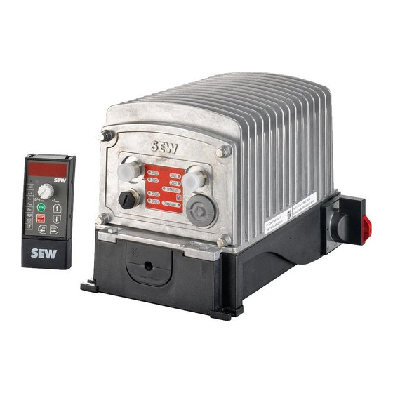
Device structure MOVIFIT® compact Device structure MOVIFIT® compact ® MOVIFIT compact ® MOVIFIT compact is a decentralized drive unit for controlling AC motors. The following image shows a MOVIFIT® compact dual-motor starter with AS-Inter- face: X 2 2 D I0 -I S ta tu X 2 1... -
Page 14: Type Designations
Device structure Type designations Type designations 3.3.1 Nameplate ® The image shows examples of the MOVIFIT compact inverter nameplates: ML 01 01.1234567890.0001.13 Input: 3x380..500V/2,2A/50..60Hz MBF11B503B2A2000 Output: 3x0..Uinput/2,5A/2..100Hz IP 54 16765180299 [1] Serial number [2] Type designation [3] The right nameplate can be found beneath the motor connections. 3.3.2 Type designation ®... -
Page 15: Purchase Order Numbers
Device structure Purchase order numbers Purchase order numbers ® 3.4.1 MOVIFIT compact (standard design) ® The following table shows the purchase order numbers of MOVIFIT compact with the standard designs: Device type Control via AS-Interface Binary control Type Purchase Type Purchase order num- order num-... - Page 16 Device structure Purchase order numbers ® 3.4.2 MOVIFIT compact (special design "MBF...-03") ® The following table shows the purchase order numbers of MOVIFIT compact in the special designs "MBF...-03" inverter with AS-Interface. Device type Control via AS-Interface Type Purchase order num- Inverter MBF07B-503-K2-A1-0-03 EB000128...
-
Page 17: Mechanical Installation
Mechanical installation General information Mechanical installation General information Observe the following notes for installation: • Always observe the general safety notes. ® • Only install MOVIFIT on a level, low-vibration, and torsionally rigid substructure; see chapter "Permitted mounting position". • Strictly observe all instructions referring to the technical data and the permissible conditions regarding the place of installation. -
Page 18: Installation Requirements
Mechanical installation Installation requirements Installation requirements Make sure that the following requirements are met before you start installing the device: ® • The information on the nameplate of the MOVIFIT device corresponds to the mains voltage. ® • The MOVIFIT device is undamaged (no damage caused by transport or storage). -
Page 19: Movifit ® Compact Installation
Mechanical installation MOVIFIT® compact installation MOVIFIT® compact installation ® MOVIFIT compact installation ® Secure the MOVIFIT compact device with 4 bolts as shown in the following illustra- tion: (Tightening torque 2.0 – 2.4 Nm) X2 2 DI 02 -I St at us X2 1 te rfa ST AT DI 03... -
Page 20: Electrical Installation
Electrical installation General information Electrical installation General information Observe the following notes for installation: • Always observe the general safety notes. ® • Only install MOVIFIT on a level, low-vibration, and torsionally rigid substructure; see chapter "Permitted mounting position". • Strictly observe all instructions referring to the technical data and the permissible conditions regarding the place of installation. -
Page 21: Installation Instructions
Electrical installation Installation instructions Installation instructions 5.3.1 Connecting supply system leads ® • The nominal voltage and frequency of the MOVIFIT device must correspond to the data of the supplying system. • Dimension the cable cross section according to the input current I for rated line power (see chapter "Technical data"). - Page 22 Electrical installation Installation instructions 5.3.4 Notes on PE connection WARNING Electric shock due to faulty connection of PE. Severe or fatal injuries. • Observe the following notes regarding PE connection. PE connection in the device Establish a PE connection in the device. 16938717451 PE connection on outside of housing ®...
- Page 23 Electrical installation Installation instructions 5.3.5 EMC-compliant installation INFORMATION This drive system is not designed for operation on a public low voltage supply system that supplies residential areas. This is a product with restricted availability (categories C1 to C4 according to EN ...
-
Page 24: Installation Topology
Electrical installation Installation topology Installation topology ® The following illustration shows the basic installation topology of the MOVIFIT com- pact with AS-Interface control: AC 3 x 380 – 500 V 16938768267 K: Line contactor Cable pro- Power bus (power supply cable) Motor cables tection device... -
Page 25: Power Bus Connection (Line Cable)
Electrical installation Power bus connection (line cable) Power bus connection (line cable) WARNING Electric shock due to dangerous voltages in the ABOX. Severe or fatal injuries. ® • De-energize the MOVIFIT device. Observe the minimum switch-off time after disconnection from the supply system: –... - Page 26 Electrical installation Power bus connection (line cable) 2. Pull the two interlocking lugs outwards and swivel the upper part of the ® FieldPower contact module upwards. 16938791947 3. Loosen the 4 screws and remove the strain relief brackets. Remove the two cable seals.
- Page 27 Electrical installation Power bus connection (line cable) 6. NOTICE! Penetration by moisture or dust caused by non-permissible cable seal. ® Damage to the MOVIFIT compact device. Only use cable seals that are approved for the diameter of the power supply cable (→ 2 102).
- Page 28 Electrical installation Power bus connection (line cable) 8. Screw the strain relief brackets to the ABOX and fix the power supply cable with the brackets (tightening torque: 0.6 Nm). 16938800011 9. Place the upper part of the contact module on the hinge hooks. Swivel the upper part of the contact module downwards until it engages at both sides.
- Page 29 Electrical installation Power bus connection (line cable) 11. Plug the supply system plug connector of the EBOX into the socket of the ABOX. 16938869515 12. Position the EBOX on the ABOX. Screw on the EBOX with 4 screws (tightening torque: 2 Nm). Avoid crushing the cable. X 2 2 D I0 -I S...
- Page 30 Electrical installation Power bus connection (line cable) NOTICE! Damage to device from penetration by moisture or dust from bending the power supply cable. bend the power supply cable within a minimum distance of 50 mm from the device. ® The MOVIFIT compact device only fulfills the requirements of degree of protec- tion IP54 if the power supply cable is not bent within 50 mm of the device.
-
Page 31: Motor Connection
Electrical installation Motor connection Motor connection 5.6.1 Motor connection variants WARNING Electric shock due to connecting or disconnecting plug connectors when voltage is applied. Severe or fatal injuries. • Disconnect all supply voltages. • Make sure that the device is de-energized. •... - Page 32 Electrical installation Motor connection 5.6.2 X9, (X8): Motor connection ® Plug connector X8 is only present on the MOVIFIT compact dual-motor starter. Connection The following table provides information about this connection: Function Power connection for motor with brake Connection type Q 8/0, female Connection image Name...
- Page 33 Electrical installation Motor connection Connection cable and component ® MOVIFIT Motor cable Motor connection compact Cable design: 4G2.5, unshielded, 3 m Motor without brake, W connection Part number: 18148743 Q 8/0 Open 2719757451 Motor without brake, m connection 2719762187 ® MOVIFIT Cable design: 7G2.5, unshielded, 3 m Motor with brake, W connection compact...
- Page 34 Electrical installation Motor connection Connection cable and component ® MOVIFIT Motor cable Motor connection compact Cable design: 4G2.5, unshielded, 3 m Motor without brake Part number: 18148743 Q 8/0 Open 2719757451 Motor with brake ® MOVIFIT compact motor starter 9007218424935691 Motor with brake and BSR brake controller 9007218424991499 For applications with regenerative mode, SEW‑EURODRIVE recommends the BSR brake con-...
- Page 35 Electrical installation Motor connection Motor cable connection 4-core The following table shows the conductor assignments of the 4-conductor motor cable with part number 18148743, the associated pins of the plug connector, and the associ- ated terminals at the motor: Plug connector Motor cables Terminal on motor...
-
Page 36: Control Unit Connections
Electrical installation Control unit connections Control unit connections ® The following illustration shows the designs of the control units of the MOVIFIT com- pact: ® ® MOVIFIT compact MOVIFIT compact with AS-Interface with binary control BINÄR DI03 DI01 DI02 AS-I Status DI02 DI00 AS-Interface... -
Page 37: Connections Of Movifit ® Compact With As-Interface
Electrical installation Connections of MOVIFIT® compact with AS-Interface Connection s of MOVIFIT® c ompact with AS- Interface ® Connections of MOVIFIT compact with AS-Interface 5.8.1 X21: AS-Interface connection The following table provides information on this connection: Function AS-Interface – input Connection type M12, 4-pin, male, A-coded, straight outlet Connection image Name... - Page 38 Electrical installation Connections of MOVIFIT® compact with AS-Interface 5.8.3 X23: Binary input sensor 3 The following table provides information on this connection: Function Digital input sensor 3 Connection type M12, 5-pin, female, A-coded, straight outlet Connection image Name Function +24 V DC 24 V output (sensor supply) n.
-
Page 39: Connections Of Movifit ® Compact With Binary Control
Electrical installation Connections of MOVIFIT® compact with binary control Connection s of MOVIFIT® c ompact with binary control ® Connections of MOVIFIT compact with binary control 5.9.1 X11: Signal inputs 0 and 1 The following table provides information on this connection: Function Digital inputs 0 and 1 Connection type M12, 4-pin, male, A-coded, straight outlet... - Page 40 Electrical installation Connections of MOVIFIT® compact with binary control 5.9.3 X13: Signal outputs 0 and 1 The following table provides information on this connection: Function Digital outputs 0 and 1 Connection type M12, 5-pin, female, A-coded, straight outlet Connection image Name Function +24 V DC 24 V output...
-
Page 41: Connecting The Mbbg11A Operator Panel
Electrical installation Connecting the MBBG11A operator panel 5.10 Connecting the MBBG11A operator panel ® The MOVIFIT compact device has an X50 diagnostic interface (RJ10 socket). The diagnostic interface is located on the connection block of the control unit. You must remove the screw plug before plugging the connector into the diagnostic in- terface. -
Page 42: Connecting A Pc/Laptop
Electrical installation Connecting a PC/laptop 5.11 Connecting a PC/laptop ® The MOVIFIT compact device has an X50 diagnostic interface (RJ10 socket) for startup, parameterization, and service. The diagnostic interface is located on the connection block of the control unit. You must remove the screw plug before plugging the connector into the diagnostic in- terface. -
Page 43: Startup
Startup General information Startup General information INFORMATION You must comply with the general safety notes in the chapter "Safety notes" during startup. WARNING Electric shock due to dangerous voltages in the ABOX. Severe or fatal injuries. ® • De-energize the MOVIFIT device. -
Page 44: Requirements
Startup Requirements WARNING Danger of burns due to hot surfaces of the device (e.g. the heat sink). Serious injuries. • Do not touch the device until it has cooled down sufficiently. NOTICE Danger due to arcing. Damage to electrical components. •... -
Page 45: Startup Procedure For Movifit ® Compact Inverter
Startup Startup procedure for MOVIFIT® compact inverter Startup procedure MOVIFIT® compact inverter ® Startup procedure for MOVIFIT compact inverter To start up the inverter, proceed as follows: ® 1. Check the connection of the MOVIFIT compact device. ð See chapter "Electrical installation". 2. - Page 46 Startup Startup procedure for MOVIFIT® compact inverter Parameters for PROFI mode (with 4-pole non-SEW motors) Non-SEW motor Size Setting on the Parameter ® MBBG11A op- in MOVITOOLS MotionStudio erator panel Grou Parameter Nominal motor voltage UoLt Nominal voltage Nominal motor power PoUEr Nominal power Nominal motor current...
-
Page 47: Startup Procedure For Movifit ® Compact Motor Starter
Startup Startup procedure for MOVIFIT® compact motor starter Startup procedure MOVIFIT® compact motor starter ® Startup procedure for MOVIFIT compact motor starter To start up the motor starter, proceed as follows: ® 1. Check the connection of the MOVIFIT compact device. ð... - Page 48 Startup Startup procedure for MOVIFIT® compact motor starter 6.4.1 Parameters for “Voltage limitation” operating mode ® Description The MOVIFIT compact motor starter increases the motor voltage along a ramp within the set time t = 0 ‑ 2 s up to the nominal value. The starting voltage at which the acceleration procedure begins can be set within the limits U = 40 – 80% of the motor voltage U...
- Page 49 Startup Startup procedure for MOVIFIT® compact motor starter 6.4.2 Parameters for “Current limiting” operating mode ® Description When the drive starts, the MOVIFIT compact motor starter imposes the current I into the motor. The current I is defined with parameter P13 Current limit.
-
Page 50: Assigning The As-Interface Slave Address
Startup Assigning the AS-Interface slave address Assigning the AS-Interface slave address ® SEW-EURODRIVE delivers MOVIFIT compact with AS-Interface with the address 0. The following options are available for assigning the AS-Interface address of the ® MOVIFIT compact (address 1A – 31A and 1B – 31B): •... - Page 51 Startup Assigning the AS-Interface slave address 6.5.1 Assigning the slave address using a hand-held programming device Hand-held AS-Interface programming devices offer the following functions: • Reading out and changing an AS-Interface slave address • Reading out the AS-Interface profile • Reading out and changing the data and parameter bits •...
-
Page 52: Parameterization With The Mbbg11A Operator Panel
Startup Parameterization with the MBBG11A operator panel Parameterization with the MBBG11A operator panel 6.6.1 MBBG11A operator panel description Function ® You can start up, parameterize, and control MOVIFIT compact devices in manual mode with the MBBG11A operator panel. In addition to that, the keypad displays im- portant information about the state of the drive. - Page 53 Startup Parameterization with the MBBG11A operator panel 6.6.2 Operation The following illustration shows the menu guidance of the MBBG11A operator panel: Level 1 Level 2 Level 3 S t o P Speed status Modify Accept Enter Enter Ramp up ramp up value Modify Accept...
- Page 54 Startup Parameterization with the MBBG11A operator panel Menu system If you select an icon with the <UP> or <DOWN> button, the LED of the icon illumin- ates. With icons that only represent display values, the current display value appears on the 7-segment display. Status display If the drive is enabled, the operator panel displays the calculated actual speed.
- Page 55 Startup Parameterization with the MBBG11A operator panel 6.6.3 Inverter parameterization You can only switch to the “SEtUP” menu in the operating state “No enable”. The “SEtUP” menu provides 2 startup modes: • In Easy mode (display: “EASY”) you can only start up 4-pole motors from SEW- EURODRIVE.
- Page 56 Startup Parameterization with the MBBG11A operator panel Saving parameters INFORMATION Commence startup and parameter saving by setting the value in the last menu “CALC” to “StArt”. If you exit the "SEtUP" menu using the <OUT> key without completing the startup, the previously changed values will not be saved.
- Page 57 Startup Parameterization with the MBBG11A operator panel 6.6.5 Data backup SEW-EURODRIVE recommends backing up the data set after startup. The data set ® can then be re-used for other MOVIFIT compact devices with identical motors. Switch from the main menu to the data backup menu. The data backup menu provides 2 functions: ®...
-
Page 58: Parameterization With The Pc/Laptop
Startup Parameterization with the PC/laptop Parameterization with the PC/laptop ® 6.7.1 MOVITOOLS MotionStudio ® The "MOVITOOLS MotionStudio" software package is the SEW-EURODRIVE cross- device engineering tool that you can use to access all SEW-EURODRIVE drive units. ® ® You can use MOVITOOLS MotionStudio for startup and diagnosis of the MOVIFIT compact. - Page 59 Startup Parameterization with the PC/laptop Establishing a communication and scanning the network ® In order to set up communication using MOVITOOLS MotionStudio and scan your network, proceed as follows: ü There is a serial connection between your PC/laptop and the MOVIFIT ®...
- Page 60 Startup Parameterization with the PC/laptop 3. Click the button [3]. ð This displays the settings for the communication type "Serial". 9,6 kB 18484090635 ® 4. In the "COM-Port" choice box, select the port to which the MOVIFIT compact device is connected to the PC/laptop via the USB11A interface adapter. 5.
-
Page 61: Parameter List Of The Movifit ® Compact Inverter
Startup Parameter list of the MOVIFIT® compact inverter Parameter list of the MOVIFIT® compact inverter ® Parameter list of the MOVIFIT compact inverter ® The following tables show the device-related parameters of the MOVIFIT compact in- verter. ® MOVITOOLS MBBG11A / Index Name Range of values Factory... - Page 62 Startup Parameter list of the MOVIFIT® compact inverter ® MOVITOOLS MBBG11A / Index Name Range of values Factory MotionStudio parameter no. dec. binde setting parameter no. Display dec. Display values 8642 Nominal speed [min 10546 13 Nominal power [kW] Fault memory 8366 Error code T0 [Code]...
- Page 63 Startup Parameter list of the MOVIFIT® compact inverter ® MOVITOOLS MBBG11A / Index Name Range of values Factory MotionStudio parameter no. dec. binde setting parameter no. Display dec. Motor parameters 8517 Maximum speed 15 – 6000 min 1500 min 8518 Current limit 0 – 150 % 150% Motor adjustment 1 10546 23 Boost...
- Page 64 Startup Parameter list of the MOVIFIT® compact inverter ® MOVITOOLS MBBG11A / Index Name Range of values Factory MotionStudio parameter no. dec. binde setting parameter no. Display dec. Control functions 10546 42 Operating mode LVFC ® MOVITOOLS MBBG11A / Index Name Range of values Factory MotionStudio...
- Page 65 Startup Parameter list of the MOVIFIT® compact inverter 6.8.1 Description of inverter parameters Parameter index 10546.23 Boost Range of values: 0 – 50 V A voltage boost when the drive is started increases the breakaway torque of the drive. Parameter index 10546.38 UL motor current weighting factor Range of values: 0 – 1.4 – 100 The UL motor protection function fulfills the requirements of standard UL ...
-
Page 66: Parameter List For The Movifit ® Compact Motor Starter
Startup Parameter list for the MOVIFIT® compact motor starter Parameter list for the MOVIFIT® compact motor starter ® Parameter list for the MOVIFIT compact motor starter ® The following tables show the device-related parameters of the MOVIFIT compact motor starter. ®... - Page 67 Startup Parameter list for the MOVIFIT® compact motor starter ® MOVITOOLS MBBG11A / Index Name Range of values Factory MotionStudio parameter no. dec. binde setting parameter no. Display dec. Display values 8367 Error code T1 [Code] 9305 Sub-error code T1 [Code] 8884 Internal error T1...
- Page 68 Startup Parameter list for the MOVIFIT® compact motor starter ® MOVITOOLS MBBG11A Index Name Range of values Factory MotionStudio parameter no. dec. binde setting parameter no. dec. Monitoring functions Start phase monitoring time 10546 209 Monitoring time for start 0 – 5 s 3 s phase drive 1 10546 210...
- Page 69 Startup Parameter list for the MOVIFIT® compact motor starter ® MOVITOOLS MBBG11A / Index Name Range of values Factory MotionStudio parameter no. dec. binde setting parameter no. Display dec. Unit functions Setup 8594 Load factory setting Reset behavior STOP RESET 8617 Manual reset 6.9.1...
- Page 70 Startup Parameter list for the MOVIFIT® compact motor starter Parameter index 10546.211/10546.212 Drive 1/2 starting voltage Range of values: 40 – 50 – 80% of nominal motor voltage If the output is insufficient to start the motor with the preset values, increase the start- ing voltage U of the drive (P10546.211/P10546.212).
- Page 71 Startup Parameter list for the MOVIFIT® compact motor starter Parameter index 10546.215/10546.216 Boost mode, drive 1/2 Range of values: Off, on Boost mode can be activated if an increased breakaway torque is required. If boost mode is activated, the motor is activated with the boost voltage U after en- abling before the soft start begins.
-
Page 72: Functions Of The Movifit ® Compact With As-Interface
Startup Functions of the MOVIFIT® compact with AS-Interface Functions of the MOVIFIT® compact with AS- Interface ® 6.10 Functions of the MOVIFIT compact with AS-Interface ® 6.10.1 AS-Interface master → MOVIFIT compact data transmission ® MOVIFIT compact inverter The following table shows the 4 data bits that the AS-Interface master transmits to the ®... - Page 73 Startup Functions of the MOVIFIT® compact with AS-Interface ® 6.10.2 MOVIFIT compact → AS-Interface master data transmission (default mode, P-600 = 0) ® The following table shows the 4 data bits that the MOVIFIT compact transmits back to the AS-Interface master: AS-Interface bit Meaning DI03 DI02 DI01 DI00 1/0 Ready signal...
-
Page 74: Functions Of The Movifit ® Compact With Binary Control
Startup Functions of the MOVIFIT® compact with binary control Functions of the MOVIFIT® compact with binary control ® 6.11 Functions of the MOVIFIT compact with binary control ® 6.11.1 PLC → MOVIFIT compact data transmission ® MOVIFIT compact inverter The following table shows the control signals that the higher-level controller transmits ®... - Page 75 Startup Functions of the MOVIFIT® compact with binary control ® 6.11.2 MOVIFIT compact → PLC data transmission (default mode, P-600 = 0) ® The following table shows the binary signals that the MOVIFIT compact transmits back to the higher-level controller (e.g. PLC): Binary sig- Meaning nals...
-
Page 76: Operation
Operation General information Operation General information INFORMATION You must comply with the general safety notes in the chapter "Safety notes" during startup. WARNING Electric shock caused by dangerous voltages at the connections, cables, and motor terminals. When the device is switched on, dangerous voltages can occur at the connectors and at any connected cables and motor terminals. -
Page 77: Movifit® Compact Operating Displays (Leds)
Operation MOVIFIT® compact operating displays (LEDs) MOVIFIT® compact operating displays (LEDs) MOVIFIT® compact operating displays (LEDs) ® The following illustration shows the LEDs of the MOVIFIT compact: ® ® MOVIFIT compact with AS-Interface MOVIFIT compact with binary control BINÄR DI03 DI01 DI02 AS-I Status... - Page 78 Operation MOVIFIT® compact operating displays (LEDs) 7.2.3 "STATUS" LED Meaning No voltage supply. ® Green The MOVIFIT compact drive is enabled. Illuminates ® Yellow The MOVIFIT compact drive is operational. Illuminates ® Yellow The MOVIFIT compact drive has been locked by the MBBG11A oper- ®...
-
Page 79: Operating Displays Of The Mbbg11A Operator Panel
Operation Operating displays of the MBBG11A operator panel Operating displays of the MBBG11A operator panel The MBBG11A operator panel has the following operating displays: ® StoP The power stage of the MOVIFIT is switched off (with inverter). ® 1 S b Y The power stage of the MOVIFIT for motor 1 is switched off (with re- versing or dual-motor starter). - Page 80 Operation Operating displays of the MBBG11A operator panel Display of fixed setpoint number (fixed setpoint menu) Press the <ENTER> key. Select the fixed setpoint in [min 1500 Display of maximum speed in [min Press the <ENTER> key. Select the maximum speed. Display of the parameter number (parameter menu) Press the <ENTER>...
-
Page 81: Manual Operation With The Mbbg11A Operator Panel
Operation Manual operation with the MBBG11A operator panel Manual operation with the MBBG11A operator panel 7.4.1 Manual mode ® For manual operation of the MOVIFIT compact, the MBBG11A operator panel has the following modes: • Binary signal specification mode (for inverters and motor starters) ®... - Page 82 Operation Manual operation with the MBBG11A operator panel 7.4.2 Activating manual operation WARNING Risk of crushing due to unexpected start-up of the drive. The signals of the MB- BG11A operator panel are effective immediately when manual mode is activated. The drive operates at the speed that is specified by the MBBG11A operator panel. Severe or fatal injuries.
- Page 83 Operation Manual operation with the MBBG11A operator panel 7.4.3 Manual operation in binary signal specification mode ® Control the MOVIFIT compact drive in binary signal specification mode as follows: 1. Open “Binary signal specification mode” as described in chapter “Activating manual operation”.
- Page 84 Operation Manual operation with the MBBG11A operator panel 7.4.4 Manual operation in setpoint adjuster mode WARNING Risk of crushing due to unexpected start-up of the drive. When you activate the con- troller in setpoint adjuster mode, the drive starts with the setpoint that is set at the setpoint adjuster (potentiometer).
- Page 85 Operation Manual operation with the MBBG11A operator panel Deactivating manual operation WARNING Risk of crushing due to unexpected start-up of the drive. The signals of the higher- level controller are effective immediately when automatic operation is activated. The drive runs with the speed that is specified by the higher-level controller. Severe or fatal injuries.
-
Page 86: Service
Service "STATUS” LED error codes Service "STATUS” LED error codes ® The “Status” LED signals the following error codes of the MOVIFIT compact: Code Meaning Color Status F 50 Error in supply voltage of internal power section (inverter or is lit motor starter) All errors that are not mentioned in this table. -
Page 87: Movifit ® Compact Error List
Service MOVIFIT® compact error list MOVIFIT® compact error list ® MOVIFIT compact error list ® The MBBG11A operator panel displays the error codes that occur at the MOVIFIT compact. ® 8.2.1 MOVIFIT compact inverter error list Code Subcode Meaning Possible cause Measure F 01 Overcurrent in output stage Short circuit at in-... - Page 88 Service MOVIFIT® compact error list Code Subcode Meaning Possible cause Measure F 43 Internal communication Communication • Contact SEW‑EURODRIVE Service. error problem between internal control section and power section. F 45 Initialization error Current offset • Reset the error. measurement out •...
- Page 89 Service MOVIFIT® compact error list ® 8.2.2 Error list for MOVIFIT compact motor starter Code Subcode Meaning Possible cause Measure • Check the connection between the F 01 Overcurrent at motor ter- Short circuit at starter output and the motor. minal X9 starter output •...
- Page 90 Service MOVIFIT® compact error list Code Subcode Meaning Possible cause Measure F 50 Supply voltage error in in- • Contact SEW‑EURODRIVE Service. ternal power section • Lower the ambient temperature at F 84 Thermal motor overload at Ambient temper- the motor. ature at motor too high •...
-
Page 91: Reset
Service Reset Reset WARNING Electric shock due to dangerous voltages in the ABOX. Severe or fatal injuries. ® • De-energize the MOVIFIT device. Observe the minimum switch-off time after disconnection from the supply system: – 1 minute WARNING Danger if the motor starts up unintentionally. Fatal or severe injuries and damage to property. -
Page 92: Inspection/Maintenance
Service Inspection/maintenance Inspection/maintenance ® 8.4.1 MOVIFIT device ® The MOVIFIT device is maintenance-free. SEW‑EURODRIVE does not prescribe any ® inspection or maintenance work for the MOVIFIT device. INFORMATION Do not open any internal components of the device. Repairs to the device may only be carried out by SEW-EURODRIVE. -
Page 93: Technical Data
Technical data Conformity Technical data Conformity 9.1.1 CE marking • Low voltage directive: ® The MOVIFIT drive system fulfills the regulations of the low voltage directive 2014/35/EU. • Electromagnetic compatibility (EMC): ® MOVIFIT compact devices are intended to be used as components for installing in machinery and systems. -
Page 94: Movifit ® Compact Inverter
Technical data MOVIFIT® compact inverter MOVIFIT® compact inverter ® MOVIFIT compact inverter ® MOVIFIT compact type MBF07B-.. MBF11B-.. MBF15B-.. Apparent output power with 1.8 kVA 2.2 kVA 2.8 kVA = AC 380 – 500 V line Connection voltages 3 x AC 380 V –10% – AC 500 V ±10% Mains Line frequency 50 – 60 Hz ±5% Mains Nominal line current AC 1.5 A AC 2.2 A AC 2.8 A Mains... - Page 95 Technical data MOVIFIT® compact inverter ® MOVIFIT compact type MBF07B-.. MBF11B-.. MBF15B-.. Installation altitude h ≤ 1000 m: no reduction h > 1000 m: I reduction 1% per 100 m h > 2000 m: U reduction AC 6 V per 100 m, Mains overvoltage class 2 in accordance with EN 60664-1 = 4000 m Mass 4.5 kg Dimensions See chapter “Dimension drawing”...
-
Page 96: Movifit ® Compact Reversing Starter
Technical data MOVIFIT® compact reversing starter MOVIFIT® compact reversing starter ® MOVIFIT compact reversing starter ® MOVIFIT compact type MBS2RB-.. MBS4RB-.. Connection voltages 3 × AC 380 V –10% – AC 500 V +10% line Line frequency 50 – 60 Hz ±5% line Output voltage line The motor output is not short-circuit-proof. - Page 97 Technical data MOVIFIT® compact reversing starter ® MOVIFIT compact type MBS2RB-.. MBS4RB-.. Storage temperature –25 °C to +85 °C (EN 60721-3-3, class 3K3) Permissible vibration and 3M5 according to EN 50178 impact load ® Degree of protection IP55 (MOVIFIT compact housing closed and all plug connections sealed off). Degree of pollution Rated short-circuit current 5 kA...
-
Page 98: Movifit ® Compact Dual-Motor Starter
Technical data MOVIFIT® compact dual-motor starter MOVIFIT® compact dual-motor starter ® MOVIFIT compact dual-motor starter ® MOVIFIT compact type MBS4DB-.. Connection voltages 3 × AC 380 V –10% – AC 500 V +10% line Line frequency 50 – 60 Hz ±5% line Output voltage line The motor outputs are not short-circuit-proof. - Page 99 Technical data MOVIFIT® compact dual-motor starter ® MOVIFIT compact type MBS4DB-.. Storage temperature –25 °C to +85 °C (EN 60721-3-3, class 3K3) Permissible vibration and 3M5 according to EN 50178 impact load ® Degree of protection IP55 (MOVIFIT compact housing closed and all plug connections sealed off). Degree of pollution Rated short-circuit current 5 kA...
-
Page 100: As-Interface Technical Data
Technical data AS-Interface technical data AS-Interface technical data 9.5.1 AS-Interface technical data, standard version AS-Interface (inverter and motor starter) Control input (X21) Connecting the AS-Interface using M12 plug connector Control functions DO00 – DO03 (→ 2 72) Signaling functions DI00 – DI03 (→ 2 72) Protocol variant AS-Interface binary slave with S-7.A.7.7 profile "4I/4O-AB-Slave"... -
Page 101: Digital Inputs (As-Interface)
Technical data Digital inputs (AS-Interface) Digital inputs (AS-Interface) Digital inputs Sensor connections DI02 Digital input sensor 2 (X22, X23) DI03 Digital input sensor 3 Sensor inputs PLC compatible according to EN 61131-2, sampling cycle ≤ 8 ms approx. 3.0 kΩ approx. 10 mA Signal level +15 – +30 V "1"... -
Page 102: Accessories And Options
Technical data Accessories and options Accessories and options 9.9.1 MBBG11A Type MBBG11A Part number 28230809 0/-n STOP Function Keypad RESET Enter With 3 m long connecting cable and plug connector RJ10 for connection to diagnostic interface X50 Degree of protection IP20 (EN 60529) without mounting Ambient temperature 0 – +50 °C Storage temperature... -
Page 103: Dimension Drawing
Technical data Dimension drawing 9.10 Dimension drawing 9.10.1 MOVIFIT® compact dimension drawing DI02 AS-I Status AS-Interface STATUS DI03 Diagnose min. 150 255.5 min. 150 9007216194831883 ® Operating Instructions – MOVIFIT compact... -
Page 104: Address List
Fax +213 21 8222-84 Bellevue http://www.reducom-dz.com 16200 El Harrach Alger info@reducom-dz.com Argentina Assembly Buenos Aires SEW EURODRIVE ARGENTINA S.A. Tel. +54 3327 4572-84 Sales Ruta Panamericana Km 37.5, Lote 35 Fax +54 3327 4572-21 (B1619IEA) Centro Industrial Garín http://www.sew-eurodrive.com.ar Prov. de Buenos Aires sewar@sew-eurodrive.com.ar... - Page 105 Address list Cameroon Sales Douala SEW-EURODRIVE S.A.R.L. Tel. +237 233 39 02 10 Ancienne Route Bonabéri Fax +237 233 39 02 10 P.O. Box info@sew-eurodrive-cm B.P 8674 Douala-Cameroun Canada Assembly Toronto SEW-EURODRIVE CO. OF CANADA LTD. Tel. +1 905 791-1553 Sales 210 Walker Drive Fax +1 905 791-2999...
- Page 106 Address list Colombia Assembly Bogota SEW-EURODRIVE COLOMBIA LTDA. Tel. +57 1 54750-50 Sales Calle 17 No. 132-18 Fax +57 1 54750-44 Service Interior 2 Bodega 6, Manzana B http://www.sew-eurodrive.com.co Santafé de Bogotá sew@sew-eurodrive.com.co Croatia Sales Zagreb KOMPEKS d. o. o. Tel.
- Page 107 Address list France Lyon SEW-USOCOME Tel. +33 4 74 99 60 00 75 rue Antoine Condorcet Fax +33 4 74 99 60 15 38090 Vaulx-Milieu Nantes SEW-USOCOME Tel. +33 2 40 78 42 00 Parc d’activités de la forêt Fax +33 2 40 78 42 20 4 rue des Fontenelles 44140 Le Bignon Paris...
- Page 108 Address list Germany Würzburg SEW-EURODRIVE GmbH & Co KG Tel. +49 931 27886-60 Nürnbergerstraße 118 Fax +49 931 27886-66 97076 Würzburg-Lengfeld dc-wuerzburg@sew-eurodrive.de Drive Service Hotline / 24 Hour Service 0 800 SEWHELP 0 800 7394357 Great Britain Assembly Normanton SEW-EURODRIVE Ltd. Tel.
- Page 109 Address list Indonesia Surabaya PT. TRIAGRI JAYA ABADI Tel. +62 31 5990128 Jl. Sukosemolo No. 63, Galaxi Bumi Permai Fax +62 31 5962666 G6 No. 11 sales@triagri.co.id Surabaya 60111 http://www.triagri.co.id Surabaya CV. Multi Mas Tel. +62 31 5458589 Jl. Raden Saleh 43A Kav. 18 Fax +62 31 5317220 Surabaya 60174 sianhwa@sby.centrin.net.id...
- Page 110 Address list Lebanon Sales (Lebanon) Beirut Gabriel Acar & Fils sarl Tel. +961 1 510 532 B. P. 80484 Fax +961 1 494 971 Bourj Hammoud, Beirut ssacar@inco.com.lb Sales (Jordan, Kuwait , Beirut Middle East Drives S.A.L. (offshore) Tel. +961 1 494 786 Saudi Arabia, Syria) Sin El Fil.
- Page 111 Fax +595 21 3285539 Departamento Central sewpy@sew-eurodrive.com.py Fernando de la Mora, Barrio Bernardino Peru Assembly Lima SEW EURODRIVE DEL PERU S.A.C. Tel. +51 1 3495280 Sales Los Calderos, 120-124 Fax +51 1 3493002 Service Urbanizacion Industrial Vulcano, ATE, Lima http://www.sew-eurodrive.com.pe sewperu@sew-eurodrive.com.pe...
- Page 112 Address list Sambia representation: South Africa Senegal Sales Dakar SENEMECA Tel. +221 338 494 770 Mécanique Générale Fax +221 338 494 771 Km 8, Route de Rufisque http://www.senemeca.com B.P. 3251, Dakar senemeca@senemeca.sn Serbia Sales Belgrade DIPAR d.o.o. Tel. +381 11 347 3244 / +381 11 288 0393 Ustanicka 128a Fax +381 11 347 1337 PC Košum, IV floor...
- Page 113 Address list South Korea Busan SEW-EURODRIVE KOREA CO., LTD. Tel. +82 51 832-0204 28, Noksansandan 262-ro 50beon-gil, Fax +82 51 832-0230 Gangseo-gu, Busan, Zip 618-820 Spain Assembly Bilbao SEW-EURODRIVE ESPAÑA, S.L. Tel. +34 94 43184-70 Sales Parque Tecnológico, Edificio, 302 Fax +34 94 43184-71 Service 48170 Zamudio (Vizcaya)
- Page 114 Address list Ukraine Assembly Dnipropetrovsk ООО «СЕВ-Евродрайв» Tel. +380 56 370 3211 Sales ул. Рабочая, 23-B, офис 409 Fax +380 56 372 2078 Service 49008 Днепр http://www.sew-eurodrive.ua sew@sew-eurodrive.ua Uruguay Assembly Montevideo SEW-EURODRIVE Uruguay, S. A. Tel. +598 2 21181-89 Sales Jose Serrato 3569 Esqina Corumbe Fax +598 2 21181-90 CP 12000 Montevideo...
-
Page 115: Index
Index Index Icons Sensor 3, X23.......... 38 Connection diagram .......... 24 “STATUS” LED fault diagnosis ...... 86 Control signals of the AS-Interface master.. 72 Control signals of the binary control .... 74 Copyright notice ............ 7 Accessories ............ 102 AS-Interface ............ 100 Connection ............. - Page 116 Index Technical data .......... 102 MBBG11A operator panel ........ 52 Grounded star point.......... 20 Motor cable............ 32 Mounting dimensions .......... 19 Mounting position .......... 18 Hazard symbols ® MOVITOOLS MotionStudio........ 58 Meaning............ 6 Establishing communication...... 59 Hybrid ABOX First steps............ 58 Connection for diagnostic interface ..
- Page 117 Index ® ® MOVIFIT compact motor starter .... 66 MOVIFIT compact motor starter .... 47 Parameterization Prerequisites .......... 44 With the MBBG11A operator panel .... 52 Safety notes ........... 12 PC, connection ............ 42 Startup instructions.......... 43 Product names ............ 7 Storage ..............
- Page 120 SEW-EURODRIVE—Driving the world SEW-EURODRIVE GmbH & Co KG P.O. Box 3023 76642 BRUCHSAL GERMANY Phone +49 7251 75-0 Fax +49 7251 75-1970 sew@sew-eurodrive.com www.sew-eurodrive.com...
Need help?
Do you have a question about the MOVIFIT compact and is the answer not in the manual?
Questions and answers