Table of Contents
Advertisement
Quick Links
Advertisement
Table of Contents

Related Manuals for THORLABS DFB13TK


Summary of Contents for THORLABS DFB13TK
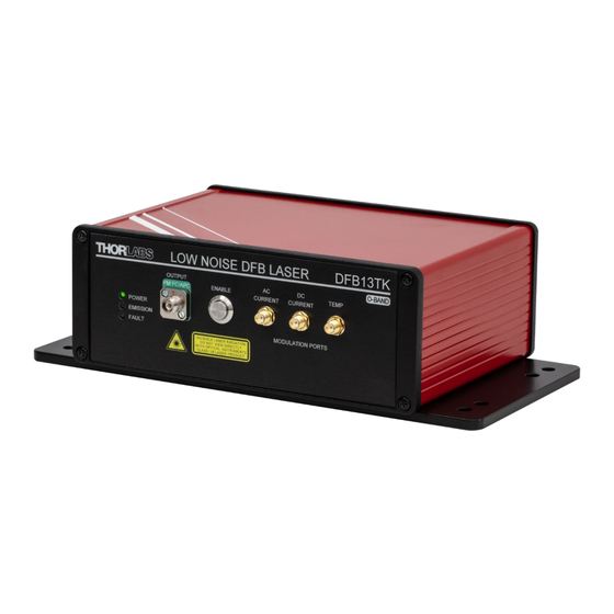
- Page 1 DFB13TK Low-Noise DFB Laser System User Guide...
-
Page 2: Table Of Contents
List of States ..............................13 4.4.2 List of Tags ................................. 13 4.4.3 List of Names ..............................14 Chapter 5 Maintenance and Cleaning ..................16 Chapter 6 Troubleshooting and Repair ..................16 Chapter 7 Disposal ........................17 Chapter 8 Thorlabs Worldwide Contacts ..................18... -
Page 3: Chapter 1 Introduction
The DFB13TK is intended to be used in a laboratory environment. For optimal performance the DFB13TK should be bolted down to an optical table or breadboard when in use. The DFB13TK should only be powered with the supplied Thorlabs DS12 power supply. -
Page 4: Technical Data
Low-Noise DFB Laser System Chapter 1: Introduction Technical Data 1.4.1 Specifications Laser Specifications (Taken at Factory Preset Operating Conditions) Symbol Typical Center Wavelength λ 1305 nm 1315 nm Output Power 100 mW Laser Linewidth Δv 100 kHz 200 kHz Mode-Hop-Free Operating Current 50 mA 500 mA Mode-Hop-Free... - Page 5 Low-Noise DFB Laser System Chapter 1: Introduction Typical External Modulation Specifications AC-Coupled Modulation Port Voltage to Current Conversion Rate 10 mA/V AC-Coupled Modulation Laser Wavelength Tuning Range ±0.15 nm AC-Coupled Modulation Laser Power Tuning Range ±10 mW DC-Coupled Modulation Port Voltage to Current Conversion Rate 2 mA/V DC-Coupled Modulation Laser Wavelength Tuning Range ±0.03 nm...
-
Page 6: Graphs
Low-Noise DFB Laser System Chapter 1: Introduction 1.4.2 Graphs DFB13TK Relative Intensity Noise (RIN) -110 -130 -150 -170 Frequency (Hz) Figure 1 Typical Low-Frequency Relative Intensity Noise (RIN) DFB13TK Frequency Noise Spectral Density 106 kHz Linewidth Frequency (Hz) Figure 2... - Page 7 1307 1309 1311 Wavelength (nm) Figure 3 Typical Output Spectrum at Factory-Set Conditions DFB13TK Output Power vs. Current Power at 15 °C Power at 20 °C Power at 25 °C Power at 30 °C Power at 35 °C 100 150 200 250 300 350 400 450 500...
- Page 8 Low-Noise DFB Laser System Chapter 1: Introduction DFB13TK Temperature and Current Tuning 1310 T = 15 °C T = 20 °C 1309 T = 25 °C T = 30 °C T = 35 °C 1308 1307 1306 1305 100 150 200 250 300 350 400 450 500...
-
Page 9: Mechanical Drawings
Low-Noise DFB Laser System Chapter 1: Introduction 1.4.3 Mechanical Drawings Figure 6 Mechanical Drawing Rev. A, August 16, 2024 Page 7... -
Page 10: Front And Back Panel Overview
Pin Diagram The DFB13TK can be interfaced via RS485 half-duplex (2-wire) according to the below pinout table. Pins 8 and 9 are for factory configuration use only. Do not connect to pins 8 and 9. Pins 3, 4, and 6 have no internal connections and should not be used. -
Page 11: Simplified Declaration Of Conformity
RS-485 Connection (M8 Connector for DS12 Power Supply) (9-Pin Male D-Sub) Figure 8 Rear Panel of the DFB13TK Laser System Simplified Declaration of Conformity The full text of the EU declaration of conformity is available at the following internet address: https://www.thorlabs.com/newgrouppage9.cfm?objectgroup_id=16787... -
Page 12: Chapter 3 Installation
If necessary, ask for replacement packaging. Refer servicing to qualified personnel. Packing List The DFB13TK laser system consists of the following components: • Low-Noise DFB Laser System •... -
Page 13: Chapter 4 Operation
10 minutes of warm-up time after it has been enabled to reach its specified linewidth. 9. Laser emission can be turned off with another toggle of the Enable push-button. 10. At any time, if the DFB13TK system detects a fault, the status indicator will light up solid and the laser will be shut off. -
Page 14: Command/Response Structure
Low-Noise DFB Laser System Chapter 4: Operation and supports modulation frequencies from 2 kHz to 20 MHz. The DC current modulation port is DC-coupled and supports frequencies from 0 Hz to 5 MHz. For both current modulation ports, the input voltage range is from -5 V to +5 V. -
Page 15: List Of States
Low-Noise DFB Laser System Chapter 4: Operation List of Commands See corresponding subsections for details. Command Descriptions laser [state] Set the user requested state of the laser. write_param [tag] [value] Write a parameter to the device read_param [tag] Read a parameter from the device save_param [tag] Immediately write a parameter to EEPROM. -
Page 16: List Of Names
Low-Noise DFB Laser System Chapter 4: Operation Name Type Default Access Descriptions Value Laser Configuration 60 = Laser on 61 = Laser off (Normal) 62 = Laser off because of interlock 63 = Laser off because of one of the following faults: laser_state Int. - Page 17 Making Safety Interlock Connections The DFB13TK is equipped with a remote interlock connector located on the rear panel. In order to enable the laser, a short circuit must be applied across the terminals of the Remote Interlock connector. This connection is made available to allow the user to connect a remotely actuated switch to the connector (i.e.
-
Page 18: Chapter 5 Maintenance And Cleaning
Chapter 6 Troubleshooting and Repair Below are a few checks to help in troubleshooting problems that may arise. Please contact your local Thorlabs Technical Support office with any questions. If the unit does not appear to turn on correctly, please check the following items: Ensure that the main AC receptacle is powered. -
Page 19: Chapter 7 Disposal
Contact Thorlabs for more information. Waste treatment is your own responsibility. “End of life” units must be returned to Thorlabs or handed to a company specializing in waste recovery. Do not dispose of the unit in a litter bin or at a public waste disposal site. It is the user’s responsibility to delete all private data stored on the device prior to disposal. -
Page 20: Chapter 8 Thorlabs Worldwide Contacts
Low-Noise DFB Laser System Chapter 8: Thorlabs Worldwide Contacts Chapter 8 Thorlabs Worldwide Contacts For technical support or sales inquiries, please visit us at www.thorlabs.com/contact for our most up-to-date contact information. Corporate Headquarters Product Manufacturer Thorlabs, Inc. Thorlabs, Inc. 43 Sparta Ave... - Page 21 www.thorlabs.com...
Need help?
Do you have a question about the DFB13TK and is the answer not in the manual?
Questions and answers