Table of Contents
Advertisement
Quick Links
Advertisement
Table of Contents

Related Manuals for THORLABS DDR05


Summary of Contents for THORLABS DDR05
- Page 1 DDR05 Direct Drive Rotation Stage User Guide Original Instructions...
-
Page 2: Table Of Contents
6.1.2 For Customers In The USA ................21 6.2 Waste Electrical and Electronic Equipment (WEEE) Directive .....21 6.2.1 Compliance ...................... 21 6.2.2 Waste treatment on your own responsibility ............ 22 6.2.3 Ecological background ..................22 6.3 CE Declaration ..................23 Chapter 7 Thorlabs Worldwide Contacts ............24... -
Page 3: Chapter 1 Safety
Chapter 1 Safety 1.1 Safety Information For the continuing safety of the operators of this equipment, and the protection of the equipment itself, the operator should take note of the Warnings, Cautions and Notes throughout this handbook and, where visible, on the product itself. The following safety symbols may be used throughout the handbook and on the equipment itself. -
Page 4: Chapter 2 Overview
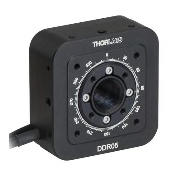
Chapter 2 Overview 2.1 Introduction The Thorlabs’ DDR05 low-profile, direct-drive rotary stage provides continuous rotation of a load with inertia moment up to 70 kg.mm with 2 µrad resolution and a maximum rotation speed of 5 Hz (300 rpm). A SM05 threaded central aperture allows an optical path to pass directly through the body of the stage. - Page 5 DDR05 Direct Drive Rotation Stage Fig. 2.1 DDR05 Direct Drive Rotation Stage Mounted on 1/2” Post...
-
Page 6: Chapter 3 Installation
Chapter 3 Installation 3.1 Unpacking Notes Retain the packing in which the unit was shipped, for use in future transportation. Caution Once removed from its packaging, the stage can be easily damaged by mishandling. The unit should only be handled by its base, not by any attachments to the moving platform. -
Page 7: Mounting
DDR05 Direct Drive Rotation Stage 3.3 Mounting Warning The safety of any system incorporating this equipment is the responsibility of the person performing the installation. Cautions When mounting the stage close to other equipment, ensure that the travel of the moving platform is not obstructed. If equipment mounted on the moving platform is driven against a solid object, damage to the internal mechanism could occur. -
Page 8: Cage Mounting
Chapter 3 3.3.2 Cage Mounting An array of threaded holes in the rotating face allow 16 mm cage system components to be fitted. The rear face is also fitted with an array of threaded holes compatible with 16 mm cage systems. By using these holes, the stage can be mounted within the cage system, and components can then be rotated within the cage. - Page 9 DDR05 Direct Drive Rotation Stage Fig. 3.2 DDR05 fitted with cage system components...
-
Page 10: Electrical Connections
Chapter 3 3.4 Electrical Connections For optimum performance, the stage must be driven by a Thorlabs TBD001 controller. Connect the flying lead to the MOTOR connector on the rear of the unit. MOTOR Fig. 3.3 Electrical connections Pin out information for the connector on the stage flying lead is detailed below.. -
Page 11: Dimensions
DDR05 Direct Drive Rotation Stage 3.5 Dimensions All dimensions in mm [in.] 3000.0 54.0 [2.13] [118.11] 30.0 [1.18] 16.0 [0.63] 54.0 30.0 30.0 [2.13] [1.18] [1.18] 5.5 [0.22] 16.0 [0.63] 4-40 UNC 4.0 [0.16] 4-40 UNC 3.0 [0.12] 4 Places for 30 mm Cage System... -
Page 12: Chapter 4 Operation
Chapter 4 Operation 4.1 General Caution The DDR05 stage is designed to be driven by the Thorlabs TBD001 Brushless DC Motor Controller. Keep clear of the moving world when the unit is in operation and rotating with equipment attached to the top plate. - Page 13 - see the handbook supplied with the TBD controller for more information. 7) If it is not already running, start the APTUser utility - Start/Programs/Thorlabs/APT User/APT User The APT server reads in the stage and controller information on boot up and the...
- Page 14 Chapter 4 Fig. 4.1 APTUser GUI screen Note The MOTOR DRIVE connectors for each channel/axis contain an EEPROM, which stores the factory default settings for the set up parameters. When the stage is connected, these settings are loaded into the controller on start up, and are tuned for loads with an inertia moment of 70kg.mm maximum, at speeds up to 300 rpm.
- Page 15 DDR05 Direct Drive Rotation Stage 8) Click the Settings button on the GUI to display the Settings panel, then select the ‘Advanced’ tab. Fig. 4.2 Advanced Control Loop Settings 9) Adjust the PID settings to fine tune the control loop for your application. Refer to the handbook supplied with the TBD series control unit for more information.
-
Page 16: Minimum And Maximum Position Settings
Min Pos and Max Pos values. This check is done to ensure that the position counter always shows a correct value. For the DDR05 stage, the Min Pos and Max Pos limits are equivalent to ±536 full rotations (193274 degrees). -
Page 17: Rotational Stage Settings
DDR05 Direct Drive Rotation Stage 4.3 Rotational Stage Settings Absolute Position Reporting Mode This setting relates to the way in which the angular position is displayed on the GUI panel. There are two options: Equivalent Angle 0 to 360 degrees – The maximum displayed position is 359.99°. -
Page 18: Stopping The Stage
Chapter 4 4.4 Stopping the Stage The drive channel is enabled and disabled by clicking the ‘Enable’ button on the GUI panel. The green indicator in the button center is lit when the drive channel is enabled. Disabling the channel removes the drive power. During operation, the stage can be stopped at any time by clicking the ‘Stop’... -
Page 19: Maintenance
The product is maintenance free up to 8,000 hours of intermittent operation. If any problems occur, the user should contact the local Thorlabs tech support for more information. After 8,000 hours, the bearing may need to be re-lubricated. Contact your local Thorlabs tech support for more information. -
Page 20: Chapter 5 Specifications
Chapter 5 Specifications 5.1 Specification Parameter Value Travel Range 360° Continuous Max Speed 5.0 Hz (1800°/s) 29.1 Hz/s (10477°/s/s) Max Acceleration Repeatability 0.00054° (9.424778 µrad) Backlash Encoder Resolution 2 x 10 counts/rev (0.00018°) Min Incremental Movement 0.00036° Maximum Moment of Inertia of Load 70 kg•mm *Note The stage can carry higher loads at lower acceleration. -
Page 21: Chapter 6 Regulatory
Chapter 6 Regulatory 6.1 Declarations Of Conformity 6.1.1 For Customers in Europe See section Section 6.3. 6.1.2 For Customers In The USA This equipment has been tested and found to comply with the limits for a Class A digital device, persuant to part 15 of the FCC rules. These limits are designed to provide reasonable protection against harmful interference when the equipment is operated in a commercial environment. -
Page 22: Waste Treatment On Your Own Responsibility
• left over parts of units disassembled by the user (PCB's, housings etc.). If you wish to return a unit for waste recovery, please contact Thorlabs or your nearest dealer for further information. 6.2.2 Waste treatment on your own responsibility If you do not return an "end of life"... -
Page 23: Ce Declaration
6.3 CE Declaration... -
Page 24: Chapter 7 Thorlabs Worldwide Contacts
Chapter 7 Thorlabs Worldwide Contacts For technical support or sales inquiries, please visit us at www.thorlabs.com/contact for our most up-to-date contact information. USA, Canada, and South America UK and Ireland Thorlabs, Inc. Thorlabs Ltd. sales@thorlabs.com sales.uk@thorlabs.com techsupport@thorlabs.com techsupport.uk@thorlabs.com Europe Scandinavia...
Need help?
Do you have a question about the DDR05 and is the answer not in the manual?
Questions and answers