
Related Manuals for THORLABS DMH40-F01


Summary of Contents for THORLABS DMH40-F01
- Page 1 Piezoelectric Deformable Mirror DMH40(/M)-F01, DMH40(/M)-P01 Operation Manual 2021...
- Page 2 Version: Date: 15-Apr-2021 Copyright © 2021 Thorlabs...
-
Page 3: Table Of Contents
Contents Foreword 1 General Information 1.1 Ordering Codes and Accessories 1.2 Requirements 1.2.1 Software Requirements 1.2.2 Hardware Requirements 2 Operating Principle 2.1 Mirror 2.2 Segment Structure 2.3 Closed Loop Control 2.4 Hysteresis of Piezoelectric Materials 2.5 Creep of Piezoelectric Materials 2.6 Relaxing the Mirror 3 Getting Started 3.1 Parts List... - Page 4 7.3 About Zernikes 7.4 Dimensions DMH40-xxx (Imperial) 7.5 Dimensions DMH40/M-xxx (Metric) 7.6 Safety 7.7 Return of Devices 7.8 Certifications and Compliances 7.9 Warranty 7.10 Copyright and Exclusion of Liability 7.11 References 7.12 Manufacturer Address 7.13 Thorlabs Worldwide Contacts and WEEE policy...
- Page 5 Paragraphs preceded by this symbol explain hazards that could damage the instrument and the connected equipment or may cause loss of data. Note This manual also contains "NOTES" and "HINTS" written in this form. Please read this advice carefully! © 2021 Thorlabs...
-
Page 6: General Information
UV-Enhanced Aluminum for 250 nm to 450 nm wavelength or Protected Silver for 450 nm to 20 mm wavelength. Compared to the Thorlabs deformable mirror DMP40, the DMH40 has a more than 2 fold larger stroke (hoisting capacity) resulting in a more than 2 fold curvature of the mirror. While, the... -
Page 7: Requirements
1.2 Requirements These are the requirements for the PC intended to be used for operation of the DMH40. 1.2.1 Software Requirements The Thorlabs Deformable Mirror software is compatible with the following operating systems: ® · Windows 7 SP1 and later (32-bit, 64-bit) ®... -
Page 8: Operating Principle
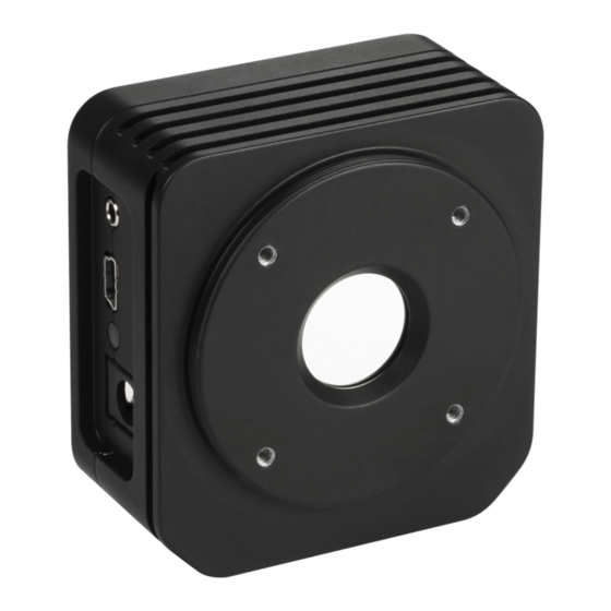
DMH40 structure - rear view showing 40 mirror segments The heart of the Thorlabs DMH40 is a deformable mirror. It is comprised of a glass substrate with a reflective coating that has a thin piezo ceramic disk with segmented electrodes glued to the back side. - Page 9 The mirror will be nearly flattened after connecting it to the power supply and to a PC with the installed Thorlabs Deformable Mirror software! The reason is that the software will initialize the hardware only after PC connection is made. Whenever no power is connected to the DMH40, the mirror will be concave (0 V position).
-
Page 10: Segment Structure
The segments 25 to 40, surrounding the mirror pupil, are used to get defined curvatures even at the pupil's rim. This improves the quality and amplitude of the Zernike terms generation. © 2021 Thorlabs... -
Page 11: Closed Loop Control
2 Operating Principle 2.3 Closed Loop Control The Thorlabs Deformable Mirror software allows for closed loop control using a sensor and the DMH40 to be set up in order to achieve flat, spherical, or other wavefront shapes. Basically, there are two methods to build closed loop feedback: either by using a photo detector with the analog feedback input of the DMH40 (1) or by using a wavefront sensor feedback loop with the respective software solution (2). - Page 12 DMH40 The Thorlabs Deformable Mirror software uses the wavefront sensor measurement data provided via the WFS DataSocket interface (included with the Thorlabs Wavefront Sensor soft- ware). In the section Closed Loop Control of this manual, this control loop method is described.
-
Page 13: Hysteresis Of Piezoelectric Materials
Consequently, when controlling the DMH40 via the Thorlabs Deformable Mirror software, the mirror behaves almost like a mirror without a hysteresis effect. Both tracks of the hysteresis curve will collapse to a straight line. -
Page 14: Creep Of Piezoelectric Materials
Drift after Power-On (Linear Time Scale) The majority of the creep is observed within half an hour but it goes on over many hours. In log- arithmic scale the drift appears as a nearly straight line: Drift after Power-On (Logarithmic Time Scale) © 2021 Thorlabs... - Page 15 2 Operating Principle Relaxing the Creep The Thorlabs Deformable Mirror software offers a Relax function. By pressing the appropri- ate button, the control voltages of all segments are increased and decreased sequentially, start- ing at the full range (0 to 300 V) with subsequent decreasing amplitude, reaching at the end the mean voltage of 150 V.
- Page 16 Even if a voltage pattern that produced a defined wavefront is reproduced exactly, the original defined wavefront will not be reproduced exactly. The Thorlabs Deformable Mirror software is not able to compensate for the creep effect. Creep- ing can be eliminated only within a closed loop control system. In other words, piezoelectric de- formable mirrors cannot be used to exactly set a deterministic wavefront distortion.
-
Page 17: Relaxing The Mirror
The effects described above are more significant, the larger the change in the applied voltage. The Thorlabs Deformable Mirror software provides a Relax feature to eliminate or at least to minimize the above impacts. It will carry out 3 steps: 1. -
Page 18: Getting Started
1. DMH40 or DMH40/M Deformable Mirror 2. SM2CP1 threaded cap 3. USB 2.0 cable A to Mini B, length 1.5 m 4. Power supply 100 to 240 V AC to 12 V / 1.5A DC 5. Power Cord 6. Quick Reference © 2021 Thorlabs... -
Page 19: Operation
Please do so. After the reboot, the installer continues with installing the DMH40 software. A Readme screen comes up with important information about the installed software. Click Next > and in the next screen Finish to finalize installation process. © 2021 Thorlabs... -
Page 20: Mounting
The SM2 external thread allows mounting of appropriate mounting optics or lens tubes. To mount a Thorlabs 30 mm cage system, both DMH40 and DMH40/M offer four 4-40 inner threads with 5 mm depth on the front of the device. -
Page 21: Out-Of-The-Box Test
In case two Deformable Mirrors were connected to the PC, select and connect the Deform- able Mirror of choice. Note Pressing the keyboard button F1 calls up online help to the Thorlabs Deformable Mirror soft- ware. 4.5 Out-of-the-Box Test It is simple to test the DMH40 "out of the box". You do not need even a light source or other op- tical equipment - just your eyes: ·... -
Page 22: Software Deformable Mirror
If the device status changes (e.g., the DMH40 is disconnected or the DMH40 power supply fails or if another Deformable Mirror connected to the PC is chosen/elected), the color turns to red and the present status is given. For details, please refer to section Troubleshooting © 2021 Thorlabs... -
Page 23: Menu Bar
- Status of hysteresis compensation - Voltage pattern that is applied to inner mirror segments - Zernike slider positions Save User Configuration You can save (and restore via the Load function) your present configuration at any time: © 2021 Thorlabs... - Page 24 DMH40 data (Zernike slider positions and segment voltages) can be restored easi- Note With updating the Thorlabs Deformable Mirror software from older versions, the file structure of the configuration files may have changed form .dmfd to .dmfc. The .dmfd files will not readily be recognized by the new software version.
- Page 25 Control Loop Settings , this selection can be made as well. The HELP Menu The keyboard button F1 brings up the online help at the first chapter. The search function allows to find the chapter of in- terest. © 2021 Thorlabs...
-
Page 26: Toolbar
Enable / disable the loop control Opens the Common Settings dialog (see below) Resets the application completely to the initial state after installation. Opens the link to the Thorlabs web site Opens the About Opens the online Help © 2021 Thorlabs... -
Page 27: Common Settings
The pattern can be flipped horizontally, vertically, or by a rota- tion angle of 0°, 45°, 90° or 135°. Besides the manual correction, the Thorlabs Deformable Mir- ror software is able to analyze the Zernike pattern orientation automatically - please see section Control Loop Parameter Determination in the manual of the DMP40. -
Page 28: Display Mirror Control
DMH40 4.6.5 Display Mirror Control The default start screen of the Thorlabs Deformable Mirror software shows the mirror segments and the voltages applied to the segments. The color of the mirror segments represents the applied voltage according to the color scheme displayed in the color bar to the right. -
Page 29: Individual Segment Control
Left click on a segment to select it. Selected parts appear with a red rim. Place the mouse pointer over a selected segment and turn the mouse wheel. The voltages of all selected ele- ments will change with the same increment: Notes © 2021 Thorlabs... -
Page 30: Control Panel
Zernike name (e.g. "Z5 Def") to reset the appropriate Zernike to its home position. Note Resetting Zernike sliders to home position means that the appropriate Zernike coefficients are set to zero. The voltage pattern on the mirror segments is generated accordingly. © 2021 Thorlabs... - Page 31 Resetting Zernike sliders to home position means that the appropriate Zernike coefficients are set to zero. The voltage pattern on the mirror segments is generated accordingly. Any segment voltages that were generated by direct mirror segment manipulation , will re- main unchanged after homing Zernikes. © 2021 Thorlabs...
-
Page 32: Mirror Manipulation
6, 19, 20, 35, 36 7, 21, 22, 37, 38 8, 23, 24, 39, 40 The made selection can be canceled by either pressing the same icon again, or via the toolbar icon 'Cancel Segment Selection' ( © 2021 Thorlabs... -
Page 33: Control Loop Settings
If no Zernikes are selected, a warning icon will be displayed in the header bar and the menu topic CONTROL LOOP is colored in red. The Control Loop menu from the menu bar offers the same settings in short form: © 2021 Thorlabs... -
Page 34: Color Bar
The color bar represents the voltage that is applied to a segment, in a certain color. There are several color tables available that can be selected in the Settings menu. Summer Autumn Winter Grey Cool (default) White © 2021 Thorlabs... -
Page 35: Status Bar
By checking the button "Don't show me this message again", you can omit further display of er- ror messages. Please see section Troubleshooting for detailed description of possible error messages. © 2021 Thorlabs... -
Page 36: Display Mirror Temperature
Click and move the mouse until you get the desired zoom factor. If necessary, repeat for the other end of the bar. Then release the mouse and move its cursor over the bar so that it changes to . Click and hold to pan the diagram: © 2021 Thorlabs... -
Page 37: The Configuration File
- Voltage pattern that is applied to mirror segments - Zernike amplitudes (for information only) - Zernike slider positions At the first start of the Thorlabs Deformable Mirror software, a default configuration is loaded. The table below shows the details of this configuration: Default Configuration... -
Page 38: Closed Loop Control
4.7 Closed Loop Control To flatten a beam wavefront, Thorlabs deformable mirrors can be run with a feedback control via a signal from a wavefront sensor. Such a setup, involving light being directed to both the wavefront sensor and the deformable mirror with feedback from the wavefront sensor through... -
Page 39: Write Your Own Application
Windows 7 (32 and 64 bit) Note Thorlabs Deformable Mirror software and drivers contains 32 bit and 64 bit applications. In 32 bit systems, only the 32 bit components are installed to C:\Program Files\... - Page 40 Data functions allow voltages of single segments or arrays of seg- ments, as well as the mirror temperatures, to be retrieved. Functions to manipulate tilt arms are only available for the DMP40. "Feedback" functions are for future use. © 2021 Thorlabs...
- Page 41 Configuration functions are different from configuration functions in the basic driver! Data functions allow the following to be retrieved: - the parameters of the extension driver - measured parameters of the control loop Convert Zernike results from wavefront sensor into DMH40 representation © 2021 Thorlabs...
-
Page 42: Instrument Driver 32Bit On 32Bit Systems
- C program how to use the extended driver functions ...\bin\TLDFMX_Sample_x86.exe - same, but executable Example for C# Project file C:\Program Files\IVI Foundation\VISA\WinNT\TLDFM\..Examples\DotNet\Sample.csproj- C:\Program Files\IVI Foundation\VISA\WinNT\TLDFMX\..Examples\DotNet\Thorlabs.TLDFMX_32.Interop.Sample.csproj- Example for LabView™ Included in driver llb container © 2021 Thorlabs... -
Page 43: Instrument Driver 32Bit On 64Bit Systems
...Examples\CSample sample.c - C program how to communicate with a DMH40 ...\bin\TLDFM_Sample_x86.exe - same, but executable C:\Program Files (x86)\IVI Foundation\VISA\WinNT\TLDFMX\..Examples\CSample sample.c - C program how to use the extended driver functions ...\bin\TLDFMX_C_Sample_x86.exe - same, but executable © 2021 Thorlabs... - Page 44 DMH40 Example for C# Project file C:\Program Files (x86)\IVI Foundation\VISA\WinNT\TLDFM\..Examples\DotNet\Sample.csproj C:\Program Files (x86)\IVI Foundation\VISA\WinNT\TLDFMX\..Examples\DotNet\Thorlabs.TLDFMX_32.Interop.Sample.csproj Example for LabVIEW™ Included in driver llb container © 2021 Thorlabs...
-
Page 45: Instrument Driver 64Bit On 64Bit Systems
C:\Program Files (x86)\Microsoft.NET\Primary Interop Assemblies..\Thorlabs.TLDFM_32.interop.dll ...\Thorlabs.TLDFMX_32.interop.dll Example for C Source code file is the same as 32bit on 64bit systems Example for C# Project file (same as 32bit on 64bit systems Example for LabVIEW™ Included in driver llb container. © 2021 Thorlabs... -
Page 46: Maintenance And Service
The DMH40 must not be cleaned from dust using ethanol, cleaning tissue, cotton tipped applic- ators or any other mechanical tools! Using these chemical and / or mechanical tools voids war- ranty! Remove dust using only oil- and water-free compressed gas, such as Thorlabs Duster CA4-US or CA4-EU (Tetrafluoroetane). - Page 47 6 Maintenance and Service Context sensitive help means that the online help opens at the point that describes the selected functionality. Example: A Zernike slider was moved. Pressing F1 brings up the section Zernike Control of the help file. © 2021 Thorlabs...
-
Page 48: Troubleshooting
AC power adapter. Then click refresh. If a DMH40 is recognized now, its type and serial number will be displayed - then click the connect button. Ø Alternatively, you can select Simulate - the Thorlabs Deformable Mirror software will open in simulation mode, the header will appear accordingly: ·... - Page 49 Ø If you need this feature, please install the WFS software that can be downloaded from the Thorlabs web site, and start the WFS software. If you have any difficulties in finding the software, please contact Thorlabs Ø...
- Page 50 Restore this option by resetting the application settings · Loading old .dmfd configuration files: With updating the Thorlabs Deformable Mirror software from older versions, the file structure of the configuration files may have changed form .dmfd to .dmfc. The .dmfd files will not readily be recognized by the new software version.
-
Page 51: Appendix
) Max. Peak-to-Valley (PV) stroke at mirror surface related to 14 mm beam diameter. The Defocus range may have an asymmetry of 30% max. Wavefront amplitudes reflected from the mirror are twice as high Note ) The control software for these mirrors includes built-in hysteresis compensation that greatly reduces the effect on mirror performance. © 2021 Thorlabs... - Page 52 Operating Altitude max. 3000 m Dimensions (W x H x D) 64 x 60 x 31 mm (w/o dust cover) Thorlabs 30 mm cage system SM2 front thread Mounting Options UNC 8-32 and UNC 1/4-20 bottom thread alternatively M4 and M6 thread (metric version) Weight 0.18 kg...
- Page 53 7 Appendix Reflectance of the UV-Enhanced Aluminum Coating Compare: https://www.thorlabs.com/newgrouppage9.cfm?objectgroup_id=264 Note The DMH40-F01 provides an average reflectance of > 89% only. © 2021 Thorlabs...
-
Page 54: Analog Feedback Connector
Closed Loop Control . The analog feedback connector is not en- closed in the shipment but may be purchased at any supplier. Connection of the external feedback connector (Stereo connector plug, Ø 2.5 mm) © 2021 Thorlabs... -
Page 55: About Zernikes
A wavefront can be described using Zernike polynomials. These are a sequence of polynomials that are orthogonal on the unit circle. A variety of definitions exist for these Zernike functions. The Thorlabs Wavefront Sensor software and this manual follows the ANSI Standard Z80.28- 210, see References The graphic below illustrates the impact of Zernikes to the wavefront. -
Page 56: Dimensions Dmh40-Xxx (Imperial)
DMH40 7.4 Dimensions DMH40-xxx (Imperial) © 2021 Thorlabs... -
Page 57: Dimensions Dmh40/M-Xxx (Metric)
Do not open the cabinet, there are no parts serviceable by the operator inside! Refer servicing to qualified personnel! Only with written consent from Thorlabs may changes to single components be made or components not supplied by Thorlabs be used. -
Page 58: Return Of Devices
This precision device is only serviceable if returned and properly packed into the complete ori- ginal packaging including the complete shipment plus the cardboard insert that holds the en- closed devices. If necessary, ask for replacement packaging. Refer servicing to qualified per- sonnel. © 2021 Thorlabs... -
Page 59: Certifications And Compliances
7 Appendix 7.8 Certifications and Compliances © 2021 Thorlabs... -
Page 60: Warranty
Thorlabs warrants material and production of the DMH40 for a period of 24 months starting with the date of shipment. During this warranty period Thorlabs will see to defaults by repair or by exchange if these are entitled to warranty. -
Page 61: References
7 Appendix 7.11 References ANSI Z80.28-2010 Ophthalmics - Methods of Reporting Optical Aberrations of Eyes: ANSI eStandards. © 2021 Thorlabs... -
Page 62: Manufacturer Address
7.12 Manufacturer Address Manufacturer Address Europe EU-Importer Address Thorlabs GmbH Thorlabs GmbH Münchner Weg 1 Münchner Weg 1 D-85232 Bergkirchen D-85232 Bergkirchen Germany Germany Tel: +49-8131-5956-0 Tel: +49-8131-5956-0 Fax: +49-8131-5956-99 Fax: +49-8131-5956-99 www.thorlabs.de www.thorlabs.de Email: europe@thorlabs.com Email: europe@thorlabs.com © 2021 Thorlabs... -
Page 63: Thorlabs Worldwide Contacts And Weee Policy
Contact Thorlabs for more information. Waste treat- ment is your own responsibility. “End of life” units must be returned to Thorlabs or handed to a company specializing in waste recovery. Do not dispose of the unit in a litter bin or at a public waste disposal site. - Page 64 ID overlay Index overlay DataSocket Inner mirror Default configuration Installation Dimensions 51, 52 Instrument status Display Mirror Control Display Mirror Temperature Display Segment Control Load 37, 38, 40 Load ... Data Drift 9, 12 Load ... Settings Only © 2021 Thorlabs...
- Page 65 Reset application settings Restore 18, 21, 24 Ring selection Safety Save user configuration Segment control 24, 27 Segment selection 18, 21, 23, 24, 27 Segment structure Segment voltage Settings Settings dialog Show ID overlay Single segment control © 2021 Thorlabs...
- Page 66 www.thorlabs.com...
Need help?
Do you have a question about the DMH40-F01 and is the answer not in the manual?
Questions and answers