Table of Contents
Advertisement
Quick Links
Advertisement
Table of Contents

Related Manuals for THORLABS GANYMEDE


Summary of Contents for THORLABS GANYMEDE
- Page 1 GANYMEDE Spectral Domain OCT System Operating Manual...
-
Page 2: Table Of Contents
Wrong Reference Intensity Setting ....................... 40 5.3. Auto-Interference ........................... 41 5.4. Multiple Scattering ..........................42 5.5. Phase Wrapping and Fringe Washout ....................43 5.6. Flipped Image ............................44 5.7. Shadowing ............................... 45 21209-D02 Rev D, September 29, 2011 Page 2 www.thorlabs.com... - Page 3 Part 9. Specifications ..........................55 Part 10. Mechanical Drawings ........................56 Part 11. Regulatory ..........................58 11.1. Waste Treatment is Your Own Responsibility ..................58 11.2. Ecological Background .......................... 58 Part 12. Thorlabs Worldwide Contacts ....................59 21209-D02 Rev D, September 29, 2011 Page 3 www.thorlabs.com...
- Page 4 Schematic of a setup to show the influence of multiple scattering ........42 Figure 45 OCT image showing multiple scattering ................42 Figure 46 Sample image showing fringe washout and phase wrapping ..........43 21209-D02 Rev D, September 29, 2011 Page 4 www.thorlabs.com...
- Page 5 Fuse cover on base unit rear panel ..................52 Figure 56 base unit dimensions ......................56 Figure 57 Imaging probe dimensions ....................56 Figure 58 Dimension of the rotation stage underneath the sample plate ..........57 21209-D02 Rev D, September 29, 2011 Page 5 www.thorlabs.com...
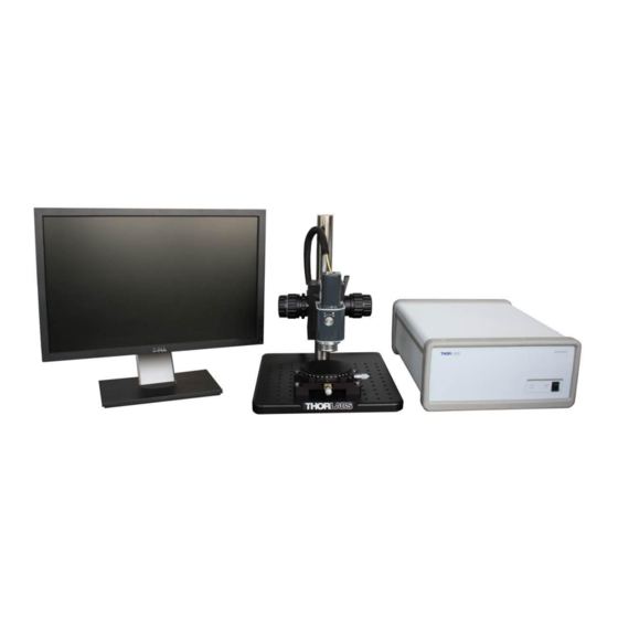
- Page 6 Spectral Domain OCT System 21209-D02 Rev D, September 29, 2011 Page 6 www.thorlabs.com...
-
Page 7: Part 1. Introduction
Opening the device will void your warranty. Any modification or servicing of this system by unqualified personnel renders Thorlabs free of any liability. This device can only be returned when packed into the complete original packaging, including all foam packing inserts. -
Page 8: Safety
Make sure that the line voltage rating agrees with your local supply and that the appropriate fuses are installed. Fuses should only be changed by qualified service personnel. Contact Thorlabs for assistance. Do not operate without cover installed. Refer servicing to qualified personnel. -
Page 9: Care And Maintenance
If this occurs, the system will need to be realigned by qualified personnel. If the system is dropped from a height greater than 15", Thorlabs will need to perform an electrical security check. Please contact Thorlabs Technical Support for more information. -
Page 10: Service
1.2.3. Accessories and Customization The GANYMEDE Spectral Domain OCT System can easily be adapted for custom interfaces. To achieve the listed specifications however this system should only be used with the accessories that Thorlabs provides. Any modification or maintenance by unqualified personnel will render the warranty null and void, leaving Thorlabs free of liability. -
Page 11: Part 2. Description
The axial resolution does not depend on the optics; it is driven by the spectral bandwidth of the light. The lateral resolution, on the other hand, is affected by the chosen application optics. 21209-D02 Rev D, September 29, 2011 Page 11 www.thorlabs.com... -
Page 12: Nomenclature In Oct Imaging
Here, the depth information is typically displayed from top to bottom, while the scan axis in Figure 2 is from left to right. Figure 3 shows a B-scan data set. Figure 3 B-scan data set 21209-D02 Rev D, September 29, 2011 Page 12 www.thorlabs.com... -
Page 13: Figure 4 Rendered Volumetric Data Set
When displaying a plane with both scan directions as axes, an en-face image is created. Here, the viewing plane is parallel to the image plane of the color camera in the probe. This plane is referred to as C-scan. Figure 5 En-Face view or C-scan 21209-D02 Rev D, September 29, 2011 Page 13 www.thorlabs.com... -
Page 14: System Components
Refer to the packing lists below to ensure that the system is complete. If any item is missing, contact Thorlabs for assistance. Do not use your own spare parts. Please use the appropriate tools when assembling a Spectral Domain SD-OCT system and handle all components of the system with care. - Page 15 #8-32 Cap Screw 3/16" Hex Key 9/64" Hex Key Note: Before operating the system, check to see if any parts have been damaged during transportation. If so, please contact Thorlabs for further assistance. 21209-D02 Rev D, September 29, 2011 Page 15 www.thorlabs.com...
-
Page 16: Base Unit
Near-IR broadband sources are a perfect compromise between sufficient transparency and a significantly reduced scattering coefficient. 21209-D02 Rev D, September 29, 2011 Page 16 www.thorlabs.com... -
Page 17: Imaging Probe
2.2.3. Imaging Probe Thorlabs SD-OCT systems use a common path OCT setup in which the interferometer is located within the imaging probe (see Figure 7). This integration of the interferometer eliminates the problems associated with chromatic and polarization mode dispersion that are introduced by differences between individual fibers in the sample and reference arms. -
Page 18: Figure 9 Optical Layout Of Imaging Probe
Figure 10 Reference Intensity Adjustment locked unlocked 21209-D02 Rev D, September 29, 2011 Page 18 www.thorlabs.com... -
Page 19: Figure 11 Reference Length Adjustment
Figure 11 Reference Length Adjustment In order to adjust the reference length adjustment knob, pull the knob approximately 5mm outwards (see fig.11). A clock-wise rotation will increase the reference length 21209-D02 Rev D, September 29, 2011 Page 19 www.thorlabs.com... -
Page 20: Probe Stand
2.2.4. Probe Stand The Thorlabs SD-OCT system is shipped with a probe stand. For setting up the probe stand, please consult the instructions that you find in the probe stand box. The probe stand is equipped with a dove tail slide for holding the probe. -
Page 21: Figure 13 Oct Stand Coarse Adjustment And Cable Clip(Rear View)
Finer focus adjustment can be done using the adjustment knobs as depicted in Figure 14. Coarse Focus Coarse Focus Adjuster Adjuster Fine Focus Adjuster Fine Focus Adjuster Dove Tail Slide Lock Ring Figure 14 OCT Stand Adjusters and Dove Tail Slide 21209-D02 Rev D, September 29, 2011 Page 21 www.thorlabs.com... -
Page 22: Figure 15 Oct Stand Sample Station
The bores of the rotation stage underneath allow for mounting of individual sample holders. A drawing of the rotation stage bores is shown in Figure 58. 21209-D02 Rev D, September 29, 2011 Page 22 www.thorlabs.com... -
Page 23: Graphical User Interface
This SD-OCT system is delivered with application software made for the imaging probes provided by Thorlabs. All required data analysis as well as 2D and 3D display can be performed within the software package. The data can be saved, analyzed and exported for further use. -
Page 24: Warning Text
CLASS 1M LASER PRODUCT KLASSIFIZIERT NACH DIN EN 60825-1:2008 CLASSIFIED ACCORDING TO DIN EN 60825-1:2008 Figure 16 Laser Emission Warning Labels Figure 17 Base Unit Warning Labels Figure 18 Imaging Probe Warning Label 21209-D02 Rev D, September 29, 2011 Page 24 www.thorlabs.com... -
Page 25: Part 3. Installation
Probe Fiber Plug (FC/APC) Auxiliary Fiber Plug (FC/APC) – not used Probe Connection Port (LEMO, 19 Pin) Auxiliary Connection Port (LEMO, 14 Pin) – not used GigE connection Port (Neutrik) 21209-D02 Rev D, September 29, 2011 Page 25 www.thorlabs.com... -
Page 26: Figure 20 Top View Of The Probe With Interconnections
Figure 21 GigE Ethernet adapter for connection to Base Unit For location of USB connectors, Monitor connections and AC plugs, please refer to the hardware manual shipped with the PC system. 21209-D02 Rev D, September 29, 2011 Page 26 www.thorlabs.com... -
Page 27: System Installation
3) Mount the probe in the probe stand by sliding the dove tail (see Figure 8) at the back of the Probe into the dove tail slide (see Figure 14) of the probe stand. Figure 22 Mounting the Probe into the dove tail slide of the OCT Stand 21209-D02 Rev D, September 29, 2011 Page 27 www.thorlabs.com... -
Page 28: Figure 23 Cameralink Frame Grabber Card Inside The Pc
5) Attach the USB cable to the base unit and to the PC. 6) Connect the power supply plug to the socket of the base unit and connect the other end to a wall plug. 21209-D02 Rev D, September 29, 2011 Page 28 www.thorlabs.com... -
Page 29: Figure 26 Plugging The Probe Connector Into The Probe
Figure 26 Plugging the probe connector into the probe Figure 27 Probe connector plugged into probe Push the connector into the plug until a ―click‖ sound is heard. 21209-D02 Rev D, September 29, 2011 Page 29 www.thorlabs.com... -
Page 30: Figure 28 Installation Of The Fiber At The Probe Fiber Connector
NOTE: If the nose slide is not properly aligned, you will still be able to secure the fiber but there will be significant light loses produced by this incorrect connection. Secure the fiber connection by turning the lock cap clockwise. No force is needed for this operation. 21209-D02 Rev D, September 29, 2011 Page 30 www.thorlabs.com... -
Page 31: Figure 29 Installing The Probe Connection At The Base Unit
Align the red dot upwards, facing the alignment mark in the base unit. alignment mark red dot Figure 29 Installing the probe connection at the base unit Push the connector into the plug until a ―click‖ sound is heard. 21209-D02 Rev D, September 29, 2011 Page 31 www.thorlabs.com... -
Page 32: Figure 30 Installation Of The Fiber At The Base Unit Connector
B and C) The fiber needs to be oriented in rotation, so that the alignment nose slides into the mating part of the probe connector. Secure the fiber connection by turning the lock cap clockwise. No force is needed for this operation. 21209-D02 Rev D, September 29, 2011 Page 32 www.thorlabs.com... -
Page 33: Figure 31 Protective Cap Removal
Spectral Domain OCT System 11) Pull the protective cap off the scan objective Do not rotate the protective cap, as this might loosen the fit of the illumination tube. Figure 31 Protective Cap Removal 21209-D02 Rev D, September 29, 2011 Page 33 www.thorlabs.com... -
Page 34: Part 4. System Operation
ON‖ indicator turns green. Wait for 30 seconds until the PC has recognized the hardware. 2) Start the Thorlabs SD-OCT software (see Software User’s Manual for details). The system will be switched on via remote control from the computer. After starting the user software, the green ―SYS OK‖... -
Page 35: Adjusting The Reference Intensity
Hit the auto-adjust button (see Software Manual) to adjust the dynamic range of your B-scan When using the IR card for adjustment, your B-scan image should look as shown in Figure 33. 21209-D02 Rev D, September 29, 2011 Page 35 www.thorlabs.com... -
Page 36: Shutting Down The System
Shutting Down the System The following steps should be followed when shutting down the system: 1) Save any important data. 2) Close the Thorlabs software. 3) Shut down the PC. 4) Turn the power switch on the base unit to ―0‖. -
Page 37: Example Images
SD-OCT provides real-time high resolution surface and sub-surface imaging of human skin, making this system ideal for many dermal and sub-dermal applications, including burn-depth monitoring, wound healing, and cancer detection. Figure 34 B-scan of a nailfold Figure 35 B-scan of a fingertip 21209-D02 Rev D, September 29, 2011 Page 37 www.thorlabs.com... -
Page 38: Figure 36 B-Scan Of A Semi-Transparent Molded Plastic Cap
Figure 36 B-scan of a semi-transparent molded plastic cap Figure 37 B-scan of a laminated IR card (not included) Biological Imaging Figure 38 B-scan of a section of a grape 21209-D02 Rev D, September 29, 2011 Page 38 www.thorlabs.com... -
Page 39: Part 5. Imaging Artifacts
A-scan axis introduction of a wedge into the optical path (first reflex reflecting outside of NA) and immersion (see Figure 40) 21209-D02 Rev D, September 29, 2011 Page 39 www.thorlabs.com... -
Page 40: Wrong Reference Intensity Setting
With low reference intensity (see picture Figure 41A), the image becomes very noisy and auto- interference is strong compared to the signal intended (frequent issue when doing thickness measurement of reflecting films). High reference intensity (see picture Figure 41B), causes saturation and loss of information. 21209-D02 Rev D, September 29, 2011 Page 40 www.thorlabs.com... -
Page 41: Auto-Interference
For thickness measurement of foils or related features, the auto-interference can be a wanted feature. For avoiding this effect, proper index matching (see Figure 40) or tilting of the sample is suggested. 21209-D02 Rev D, September 29, 2011 Page 41 www.thorlabs.com... -
Page 42: Multiple Scattering
In the OCT image (see Figure 45), one can clearly see that the paper appears to be very thick. This apparent thickness is induced by the relatively long travel of photons that are scattered multiple times before finding their way back into the detecting aperture. 21209-D02 Rev D, September 29, 2011 Page 42 www.thorlabs.com... -
Page 43: Phase Wrapping And Fringe Washout
In the middle of the movement where the speed is at its maximum almost no OCT data is displayed (fringe washout). 21209-D02 Rev D, September 29, 2011 Page 43 www.thorlabs.com... -
Page 44: Flipped Image
Incorrect reference length adjustment showing a flipped image Figure 47 and Figure 48 show correct and incorrect adjustment of the reference length when imaging the IR viewing card provided with the system. 21209-D02 Rev D, September 29, 2011 Page 44 www.thorlabs.com... -
Page 45: Shadowing
Reflections, strong scattering and absorption lead to shadows in the depth distribution of the data acquired. Figure 49 Rendered volume of a screw on an IR viewing card displaying the shadowing effect 21209-D02 Rev D, September 29, 2011 Page 45 www.thorlabs.com... -
Page 46: Image Distortion By Refractive Media
Figure 50 Schematic of a setup to show distortions from refractive media height shift Figure 51 Height shift of OCT imaging through refractive media 21209-D02 Rev D, September 29, 2011 Page 46 www.thorlabs.com... -
Page 47: The Group Refraction Index
1,794 1,749 1,773 SF57 1,822 1,871 1,817 1,857 1,806 1,832 In vacuum the values for n as well as for n are 1 for all wavelengths. The same applies for air. 21209-D02 Rev D, September 29, 2011 Page 47 www.thorlabs.com... -
Page 48: Measurement Depth In Oct Systems
The loss of imaging depth depends on the thickness and the group refractive indices of the materials displayed within the image. It is calculated as follows: loss 21209-D02 Rev D, September 29, 2011 Page 48 www.thorlabs.com... -
Page 49: Distortions In The Image
Especially when the surface is not horizontal or curved, effects like shadowing, diffraction on interfaces and possible multiple measured structures may occur in addition to the changes in optical path length. 21209-D02 Rev D, September 29, 2011 Page 49 www.thorlabs.com... -
Page 50: Figure 54 Complex Structure In Image
In very complex structures these effects become more and more difficult to handle – Just assume spherical or curved interfaces, bubbles, inhomogeneous materials, possible imaging aberrations in the sample probe etc. 21209-D02 Rev D, September 29, 2011 Page 50 www.thorlabs.com... -
Page 51: Part 6. Troubleshooting
Adjust reference intensity Reference intensity too high or too low knob Other reason Call Thorlabs Reference length set incorrectly Adjust reference length Flipped Image Please refer to Part 12 for Thorlabs contact information. 21209-D02 Rev D, September 29, 2011 Page 51 www.thorlabs.com... -
Page 52: Changing The Input Fuses
Use only IS 2A 250VAC Type T 5x20mm style fuses (IEC 60127-2/III, low breaking capacity, slow blow). Slide the fuse cover closed. 100-240 VAC 50-60 Hz 45W MAX. FUSE 500mA/250V TYPE T 250 Figure 55 Fuse cover on base unit rear panel 21209-D02 Rev D, September 29, 2011 Page 52 www.thorlabs.com... -
Page 53: Part 7. Certifications And Compliance
Spectral Domain OCT System Part 7. Certifications and Compliance 21209-D02 Rev D, September 29, 2011 Page 53 www.thorlabs.com... -
Page 54: Part 8. Warranty
Part 8. Warranty 8.1. Lasers and Imaging Systems Thorlabs offers a one year warranty on all lasers and imaging systems, with the exceptions of laser diodes. 8.2. Non-Warranty Repairs Products returned for repair that are not covered under warranty will incur a standard repair charge in addition to all shipping expenses. -
Page 55: Part 9. Specifications
Spectral Domain OCT System Part 9. Specifications Optical Performance Specifications – GANYMEDE Optical Central Wavelength 930 nm Axial Scan Rate 29 kHz Maximum Imaging Depth 2.7 mm 5.8µm / 4.4 µm Axial Resolution Air/Water (typical) General 100 V – 240 V / AC... -
Page 56: Part 10. Mechanical Drawings
Spectral Domain OCT System Part 10. Mechanical Drawings Figure 56 base unit dimensions Figure 57 Imaging probe dimensions 21209-D02 Rev D, September 29, 2011 Page 56 www.thorlabs.com... -
Page 57: Figure 58 Dimension Of The Rotation Stage Underneath The Sample Plate
Spectral Domain OCT System Figure 58 Dimension of the rotation stage underneath the sample plate 21209-D02 Rev D, September 29, 2011 Page 57 www.thorlabs.com... -
Page 58: Part 11. Regulatory
Waste Treatment is Your Own Responsibility If you do not return an ―end of life‖ unit to Thorlabs, you must hand it to a company specialized in waste recovery. Do not dispose of the unit in a litter bin or at a public waste disposal site. -
Page 59: Part 12. Thorlabs Worldwide Contacts
Spectral Domain OCT System Part 12. Thorlabs Worldwide Contacts USA, Canada, and South America Thorlabs, Inc. 435 Route 206 Newton, NJ 07860 Tel: 973-579-7227 Fax: 973-300-3600 www.thorlabs.com email: feedback@thorlabs.com Europe UK and Ireland Thorlabs GmbH Thorlabs LTD. Hans-Böckler-Str. 6 1 Saint Thomas Place, Ely... - Page 60 Thorlabs, Inc. 435 Route 206N Newton, NJ 07860 USA Phone: (973) 579-7227 ♦ Fax: (973) 300-3600 www.thorlabs.com...
Need help?
Do you have a question about the GANYMEDE and is the answer not in the manual?
Questions and answers