Table of Contents
Advertisement
Quick Links
Advertisement
Table of Contents

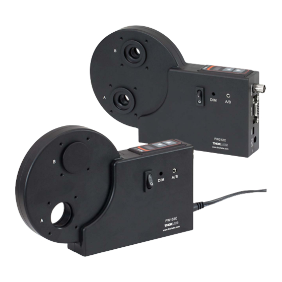
Summary of Contents for THORLABS FW102C
- Page 1 FW102C Motorized Filter Wheel User Guide Rev D, May 15, 2013...
-
Page 2: Table Of Contents
7.2. Electrical ........................13 7.3. Physical characteristics and Interface ................ 13 Chapter 8 Mechanical Drawings ......................14 Chapter 9 Regulatory ...........................15 9.1. Waste Treatment is Your Own Responsibility ............15 9.2. Ecological Background ....................15 Chapter 10 Thorlabs Worldwide Contacts ..................16 ... -
Page 3: Chapter 1 Warning Symbol Definitions
Motorized Filter Wheel Chapter 1: Warning Symbol Definitions Chapter 1 Warning Symbol Definitions Below is a list of warning symbols you may encounter in this manual or on your device. Symbol Description Direct Current Alternating Current Both Direct and Alternating Current Earth Ground Terminal Protective Conductor Terminal Frame or Chassis Terminal... -
Page 4: Chapter 2 Safety
Motorized Filter Wheel Chapter 2: Safety Chapter 2 Safety All statements regarding safety of operation and technical data in this instruction manual will only apply when the unit is operated correctly. Rev D, May 15, 2013 Page 4... -
Page 5: Chapter 3 Description
210° degrees (See the drawing on Page 14). The FW102C is designed to ensure an accuracy of greater than ±1°. The FW102C easily mounts to our lens tube systems and optical instruments via two SM1 (1.035"-40) threaded mounts. Adapters are available to interface to other popular camera, microscope, and telescope thread sizes. -
Page 6: Shipping Inventory
Motorized Filter Wheel Chapter 3: Description 3.3. Shipping Inventory The FW102C is shipped with the following: Part Description Quantity Controller with Filter Housing FW102C Filter Wheel 12 V DC Converter Power Cord USB Cable SM1CP2 End Cap SM1RR Retaining Ring... -
Page 7: Chapter 4 Basic Operation
The filter wheel cover contains SM1 threads for attaching lens tubes or for mounting the unit directly to cameras, microscopes, and telescopes. The filter wheel can be attached directly to Thorlabs’ 30 mm cage systems via four 4-40 tapped holes that surround each port. -
Page 8: Aperture
Motorized Filter Wheel Chapter 4: Basic Operation 4.4. Aperture The unit has two aperture locations labeled “A” and “B” for the 0° and 120° positions, respectively (see Figure 3 below). The A/B switch on the side of the unit selects the aperture. SM1 (Ø1.035"-40) Thread 0.15"... -
Page 9: Chapter 5 Software Control
Command Line Interface The FW102C can also be controlled by a command line language through the USB or RS232 ports. This is offered to enable operation through a terminal interface or for those who may want to write their own program to control the wheel. -
Page 10: Keywords (Commands And Queries)
Motorized Filter Wheel Chapter 5: Software Control 5.2.3. Keywords (Commands and Queries) The following table describes all of the available commands and queries: Command Syntax Description Get ID *idn? Returns the model number and firmware version Set Position pos=n Moves the wheel to filter position n Set Position Count pcount=n Sets the wheel type where n is 6 or 12... -
Page 11: Activex Control
Methods Description AboutBox Displays a dialog box with information about Thorlabs SelectComPort Displays a dialog box to select the com port that the filter wheel is connected to SelectBaudRate Displays a dialog box to select the desired baud rate for communications... -
Page 12: Chapter 6 Trouble Shooting And Maintenance
Motorized Filt ter Wheel Chapter 6: Trouble Sho oting and Ma aintenance Chapter ouble Sh hooting and Ma aintenan Dust or debris s can sometim mes set into the filter whe eel housing an nd block the sensors. This s will result in n the filter wheel failing to move to... -
Page 13: Chapter 7 Specifications
Motorized Filter Wheel Chapter 7: Specifications Chapter 7 Specifications 7.1. Performance Parameter Typical Access Time (Adjacent Locations) 900 ms Access Time (Other Locations) 2500 ms Accuracy / Repeatability ± 0.5° ± 1° Expected Cycles 1.5 x 10 7.2. Electrical Parameter Typical BNC Input Trigger Max Rate... -
Page 14: Chapter 8 Mechanical Drawings
Motorized Filter Wheel Chapter 8: Mechanical Drawings Chapter 8 Mechanical Drawings Front SM1 (Ø1.035"-40) 8 X4-40 UNC 0.100" (2.54 mm) Thread 0.15" Deep Side For 30 mm Cage Plate 2 Places Both Sides (135.41 mm) 5.33" (Ø56.36 mm) Ø2.22" (29.46 mm) 1.16"... -
Page 15: Chapter 9 Regulatory
Waste Treatment is Your Own Responsibility If you do not return an “end of life” unit to Thorlabs, you must hand it to a company specialized in waste recovery. Do not dispose of the unit in a litter bin or at a public waste disposal site. -
Page 16: Chapter 10 Thorlabs Worldwide Contacts
Motorized Filter Wheel Chapter 10: Thorlabs Worldwide Contacts Chapter 10 Thorlabs Worldwide Contacts For technical support or sales inquiries, please visit us at www.thorlabs.com/contact for our most up-to- date contact information. USA, Canada, and South America UK and Ireland Thorlabs, Inc. - Page 17 www.thorlabs.com...


Need help?
Do you have a question about the FW102C and is the answer not in the manual?
Questions and answers