
Subscribe to Our Youtube Channel
Related Manuals for THORLABS HDR50


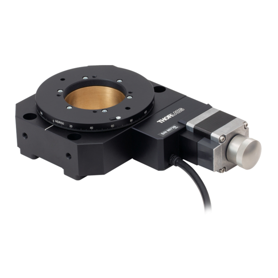
Summary of Contents for THORLABS HDR50
- Page 1 HDR50 and HDR50/M Motorized 360° Rotation Stage User Guide Original Instructions HA0393T...
-
Page 2: Table Of Contents
Chapter 2 Safety ............................. 2 2.1 Safety Information ......................2 2.2 General Warnings and Cautions ..................2 Chapter 3 Operation ..........................3 3.1 Using the HDR50 ....................... 3 3.1.1 Background ..........................3 3.2 Selecting the Stage Type ....................3 Chapter 4 Installation ..........................6 4.1 Unpacking .......................... -
Page 3: Chapter 1 Overview
These accessories include optical mounts, tip-tilt mounts, as well as fiber holders. NR360SP5 - Mounting Plate: This mounting plate allows the HDR50 stage to be attached to a LNR50 TravelMax, or NRT stage. -
Page 4: Chapter 2 Safety
HDR50 Motorized 360° Rotation Stage Chapter 2 Safety 2.1 Safety Information For the continuing safety of the operators of this equipment, and the protection of the equipment itself, the operator should take note of the Warnings, Cautions and Notes throughout this handbook and, where visible, on the product itself. -
Page 5: Chapter 3 Operation
66 x 409,600 steps per revolution of the stage. This results in a 360/(66 x 409,600)° or 13.3 x 10 degrees of platform rotation per microstep. The HDR50 stage is connected to the Stepper Motor Controller via a flying lead terminated in a D-type type connector. A 3m extension cable (PAA613) is also supplied. - Page 6 5) On start-up, the 'Actuator/Startup Settings ' window is displayed. This window allows the correct actuator to be selected. Fig. 3.1 Stage Configuration Window 6) Select your actuator type (i.e. HDR50 or HDR50/M). 7) Click OK. 8) The server reads in the stage and controller information automatically.
- Page 7 To ensure correct operation, it is important to select the correct stage and axis type as described previously. Selecting an incompatible stage/axis type could result in reduced velocity and resolution. The HDR50 is a direct replacement for our legacy NanoRotator stage and has identical operating parameters.
-
Page 8: Chapter 4 Installation
HDR50 Motorized 360° Rotation Stage Chapter 4 Installation 4.1 Unpacking Caution Once removed from its packaging, the stage is easily damaged by mishandling. The unit should only be handled by its base, not by the top platform or any attachments to the top platform. -
Page 9: Attaching To A Work Surface
Chapter 4 Installation 4.5 Mounting to the Work Surface The stage bolts directly to the work surface as shown below. Fig. 4.1 Mounting the Stage to the Work Surface 4.6 Attaching Components and Devices Caution Users must ensure that components and devices fitted to the unit are properly secured to the moving platform. Rev B Dec 2019 Page 7... -
Page 10: Chapter 5 Specification And Dimensions
HDR50 Motorized 360° Rotation Stage Chapter 5 Specification and Dimensions 5.1 Specification Parameter Value General Specifications Construction Aluminum Body and Platform Black Anodised 360° Continuous Rotation Travel 50 kg (110 lbs) Max Load Capacity (On-Rotation-Axis) Worm Drive Drive Mechanism Gear Ratio... - Page 11 2.32in 1/4 in [M6] SOCKET CAP SCREWS 59.0mm 4 PLACES 1.52 in 1.73 in 38.7 mm 44.0 mm 2.00 in 0.80 in 50.0 mm 0.97 in 20.3 mm 24.6 mm Fig. 5.1 HDR50(/M) Dimensions Rev B Dec 2019 Page 9...
-
Page 12: Chapter 6 Regulatory
HDR50 Motorized 360° Rotation Stage Chapter 6 Regulatory 6.1 Declarations Of Conformity 6.1.1 For Customers in Europe 6.1.2 For Customers In The USA This equipment has been tested and found to comply with the limits for a Class A digital device, persuant to part 15 of the FCC rules. -
Page 13: Chapter 7 Thorlabs Worldwide Contacts
Contact Thorlabs for more information. Waste treatment is your own responsibility. "End of life" units must be returned to Thorlabs or handed to a company specializing in waste recovery. Do not dispose of the unit in a litter bin or at a public waste disposal site. - Page 14 www.thorlabs.com...
Need help?
Do you have a question about the HDR50 and is the answer not in the manual?
Questions and answers