Table of Contents
Advertisement
Advertisement
Table of Contents

Related Manuals for THORLABS S4FC Series


Summary of Contents for THORLABS S4FC Series
- Page 1 S4FC Series Fiber-Coupled Laser Sources User Guide...
-
Page 2: Table Of Contents
S4FC Series Fiber Coupled Laser Source Table of Contents Chapter 1 Warning Symbol Definitions .................... 1 Chapter 2 Safety ............................ 2 2.1. Laser Safety ........................3 Chapter 3 Description ........................... 4 Chapter 4 Setup ............................. 5 4.1. Initial Set-up ........................5 Chapter 5 Operation .......................... 6 5.1. Front and Back Panel Overview ..................6 ... -
Page 3: Chapter 1 Warning Symbol Definitions
S4FC Series Fiber Coupled Laser Source Chapter 1: Warning Symbol Definitions Chapter 1 Warning Symbol Definitions Below is a list of warning symbols you may encounter in this manual or on your device. Symbol Description Direct Current Alternating Current Both Direct and Alternating Current... -
Page 4: Chapter 2 Safety
S4FC Series Fiber Coupled Laser Source Chapter 2: Safety Chapter 2 Safety SHOCK WARNING High voltage inside. To avoid electrical shock, before powering unit, make sure that the protective conductor of the 3-conductor power cord is correctly connected to the protective earth contact of the socket outlet. -
Page 5: Laser Safety
Laser Safety The S4FC series of lasers are rated in the 3B Laser Safety Class. According to Laser Institute of America: “A Class 3B laser is hazardous if the eye is exposed directly, but diffuse reflection such as from paper or other matte surfaces are not harmful. -
Page 6: Chapter 3 Description
The USB connector on the back panel allows communication with a PC using a GUI or a command line language (see section 5.9 on page 10). All S4FC series laser sources are equipped with a remote interlock connector located on the rear panel. In order to enable the laser source, a short circuit must be applied across the terminals of the remote interlock connector. -
Page 7: Chapter 4 Setup
S4FC Series Fiber Coupled Laser Source Chapter 4: Setup Chapter 4 Setup 4.1. Initial Set-up The S4FC Laser Source is designed to operate from 85 to 264 VAC and there is no need to make any adjustments as the switching power supply will determine the correct voltage automatically. Use the proper line cord for your region. -
Page 8: Chapter 5 Operation
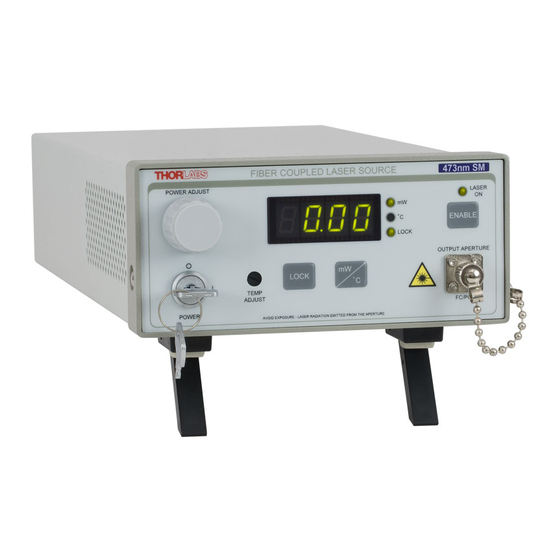
S4FC Series Fiber Coupled Laser Source Chapter 5: Operation Chapter 5 Operation 5.1. Front and Back Panel Overview LED Indicators Laser Emission Indicator Bi-color LED’s indicate Blinks for 5 seconds before selection of mW or temp laser turns ON and their status... -
Page 9: Cleaning And Connecting The Fiber Patch Cable
S4FC Series Fiber Coupled Laser Source Chapter 5: Operation 5.2. Cleaning and Connecting the Fiber Patch Cable Before Enabling the S4FC Laser Source It is necessary to clean the fiber patch cable connector tip and the connector tip inside the bulkhead connector for both safety reasons and fiber care. -
Page 10: Lock Button
S4FC Series Fiber Coupled Laser Source Chapter 5: Operation 5.4. LOCK Button The LOCK button can be pressed in the event the user would like to lock the laser and temperature setting to prevent against accidental adjustment. When LOCK is pressed, the LOCK LED will illuminate. At this time, adjustment of the rotary knob and adjustment screw will not change the Laser or Temperature set point. -
Page 11: Enabling The Laser
S4FC Series Fiber Coupled Laser Source Chapter 5: Operation Figure 3 View of Front Panel with Power Adjust Selected 1. Press LOCK so that the LOCK indicator is not lit (Unlocked). 2. Press mW/°C button to select mW. 3. Rotate PWR ADJUST knob to adjust output power to the desired level. -
Page 12: Turning The Laser Off
S4FC Series Fiber Coupled Laser Source Chapter 5: Operation 1 = Threshold: Sets the starting value to the laser diodes threshold value. 0 = Zero Power: Sets the starting value to nearly 0.1 mW power; or threshold if threshold is less than 0.1 mW. -
Page 13: 5.10. Computer Controlled Operation
5.10.1. GUI Operation The S4FC series can be controlled by a GUI run from the supplied CD. In order to run the software from another location, PC’s hard drive, thumb drive, etc., copy the files indicated below to the same directory on your storage device. - Page 14 S4FC Series Fiber Coupled Laser Source Chapter 5: Operation Note: Changing any of the settings below allows the user to make immediate changes to the controller. Panel Adjustment Range Settings Sets the enable start point See section 5.7, page 9...
-
Page 15: 5.10.2. Command Line Operation
S4FC Series Fiber Coupled Laser Source Chapter 5: Operation 5.10.2. Command Line Operation The system may also be controlled by a command line language through the USB port. This is offered to enable operation through a terminal interface or for those who may want to write their own program to control the unit. -
Page 16: Keywords (Commands And Queries)
S4FC Series Fiber Coupled Laser Source Chapter 5: Operation 5.11. Keywords (Commands and Queries) The following table describes all of the available commands and queries: Command Syntax Description Returns product header and firmware version Returns a list of all available commands... -
Page 17: Chapter 6 Connecting The Safety Interlock
Connecting the Safety Interlock The S4FC series laser source is equipped with a remote interlock connector located on the rear panel, see Figure 1, page 6. All units have this feature regardless of their FDA and IEC classifications. In order to enable the laser source, a short circuit must be applied across the terminals of the Remote Interlock connector. -
Page 18: Chapter 7 General Maintenance
Aside from the AC input fuse, there are no user serviceable parts in this product. If you suspect something has failed on the unit, please contact your local Thorlabs Technical Support Office for advice on returning the unit for evaluation. -
Page 19: Fuse Replacement
S4FC Series Fiber Coupled Laser Source Chapter 7: General Maintenance 7.3. Fuse Replacement It may be necessary to replace an open fuse. To do this you must perform the following procedure. Remove the AC power cord if it is connected to the unit. -
Page 20: Chapter 8 Troubleshooting
S4FC Series Fiber Coupled Laser Source Chapter 8: Troubleshooting Chapter 8 Troubleshooting 8.1. Error Codes When a fault is detected by the firmware, an error code is shown on the front panel LED display. Some errors, non-severe error, will allow the system to continue to operate. Others, severe errors, will cause the laser to disable. -
Page 21: Fault Tracing
Fuse(s) may be open. Refer to section 7.3, page 17 for information on replacing ON position. open fuses. If the problem persists, please return the unit to Thorlabs for evaluation. Make sure that the AC Line Cord is properly plugged in and Key Switch is turned to “ON”... -
Page 22: Chapter 9 Specifications
S4FC Series Fiber Coupled Laser Source Chapter 9: Specifications Chapter 9 Specifications Laser Specifications Max Output Power Stability at 75% Power (mW) of Max Power 15 min 24 hrs. Laser Model Wavelength Fiber Type Class Min. Typ. S4FC473 473 ± 10 nm 460HP ≤... -
Page 23: Chapter 10 Mechanical Drawing
S4FC Series Fiber Coupled Laser Source Chapter 10: Mechanical Drawing Chapter 10 Mechanical Drawing 5.92" (150.3 mm) 12.47" (316.6 mm) 3.00" (76.1 mm) October 24, 2017, Rev R Page 21... -
Page 24: Chapter 11 Regulatory
Waste Treatment is Your Own Responsibility If you do not return an “end of life” unit to Thorlabs, you must hand it to a company specialized in waste recovery. Do not dispose of the unit in a litter bin or at a public waste disposal site. -
Page 25: Chapter 12 Certificate Of Compliance
S4FC Series Fiber Coupled Laser Source Chapter 12: Certificate of Compliance Chapter 12 Certificate of Compliance October 24, 2017, Rev R Page 23... -
Page 26: Thorlabs Worldwide Contacts
Tel: +46-31-733-30-00 Fax: +49-(0) 8131-5956-99 Fax: +46-31-703-40-45 www.thorlabs.de www.thorlabs.com Email: europe@thorlabs.com Email: scandinavia@thorlabs.com France Brazil Thorlabs Vendas de Fotônicos Ltda. Thorlabs SAS Rua Rosalino Bellini, 175 109, rue des Côtes Jardim Santa Paula 78600 Maisons-Laffitte São Carlos, SP 13564-050 France Brazil... - Page 27 www.thorlabs.com...
Need help?
Do you have a question about the S4FC Series and is the answer not in the manual?
Questions and answers