Table of Contents
Advertisement
Quick Links
Advertisement
Table of Contents

Related Manuals for THORLABS MPH16-UC


Summary of Contents for THORLABS MPH16-UC
- Page 1 MPH16-UC Motorized Pinhole Wheel, Uncoated User Guide...
- Page 2 Thorlabs, Inc.
-
Page 3: Table Of Contents
MPH16 GUI (Graphical User Interface) 5.2.1. Display Area 5.2.2. Menu Chapter 6 Hardware Setup and Installation 6.1. General Setup 6.2. Choosing the Pinhole Size 6.3. Installation Chapter 7 Alignment 7.1. Laser Source Alignment 7.2. MPH16-UC Fine Manual Alignment 7.2.1. Lens Alignment... - Page 4 Motorized Pinhole Wheel, Uncoated Chapter 8 Maintaining the MPH16-UC 8.1. Cleaning 8.2. Troubleshooting Chapter 9 Specifications 9.1. General Specifications 9.2. Pinhole Wheel Specifications 9.3. Pinhole Wheel Specifications 9.4. Achromatic Doublet Specifications Chapter 10 Mechanical Drawing Chapter 11 Certifications and Compliance...
-
Page 5: Chapter 1 Warning Symbols And Definitions
Motorized Pinhole Wheel, Uncoated Chapter 1: Warning Symbols and Definitions Chapter 1 Warning Symbols and Definitions Below is a list of warning symbols you may encounter in this manual or on your device. Symbol Description Direct Current Alternating Current Both Direct and Alternating Current Earth Ground Terminal Protective Conductor Terminal Frame or Chassis Terminal... -
Page 6: Chapter 2 Safety
Motorized Pinhole Wheel, Uncoated Chapter 2: Safety Chapter 2 Safety All statements regarding safety of operation and technical data in this user guide will only apply when the unit is operated correctly. Please read the fol- lowing warnings and cautions carefully before operating the device. WARNING DO NOT use the device for anything other than its intended use. -
Page 7: Chapter 3 Description
This disk consists of 16 pinholes ranging from Ø25 µm to Ø2 mm. The MPH16-UC connects to a computer through a USB port. A DLL or GUI soft- ware controls the pinhole wheel. An optically encoded motor provides repeat- able selection between pinholes with a resolution of 10 µm, without the need for... -
Page 8: Front Panel Overview
Motorized Pinhole Wheel, Uncoated Chapter 3: Description 3.2. Front Panel Overview Figure 3–1 MPH16-UC Module Front View 3.3. Back Panel Overview Figure 3–2 MPH16-UC Module Rear View Page 4 TTN202954-D02... -
Page 9: Working Principle Of Motorized Pinhole Wheel
Motorized Pinhole Wheel, Uncoated Chapter 3: Description 3.4. Working Principle of Motorized Pinhole Wheel Figure 3–3 Cutaway Showing Beam Path Rev B, February 21, 2021 Page 5... -
Page 10: Chapter 4 Getting Started
Motorized Pinhole Wheel, Uncoated Chapter 4: Getting Started Chapter 4 Getting Started 4.1. Unpacking and Inspection Open the package, and carefully remove the MPH16-UC and its accessories. The table lists the standard accessories shipped with the device. Name Quantity Motorized Pinhole Wheel... - Page 11 Motorized Pinhole Wheel, Uncoated Chapter 4: Getting Started Connect one end of the power supply to the MPH16-UC and the other end to a standard power outlet. MPH16_Control.exe Double click the file from the Application folder saved on your local drive.
- Page 12 Motorized Pinhole Wheel, Uncoated Chapter 4: Getting Started In the MPH16 Pinhole Control window, make sure the alignment number on the front of the MPH16-UC device matches the Alignment number in the MPH16 Pinhole Control window for the 25 μm pinhole diameter size.
-
Page 13: Chapter 5 Software
Chapter 5: Software Chapter 5 Software 5.1. MPH16 4.0 Software Installation Download the software from www.thorlabs.com and open the 70- 0034-4.0 MPH16 SDK v4.0 folder. Double click the installer (.exe) application to open the MPH16 4.0 Setup window. Click Next to continue. - Page 14 In the Choose Components window, select SDK if you want the soft- ware development kit files installed, then click Next. Figure 5–2 Choose Components Window In the Choose Install Location window, select the destination folder and then click Install. Figure 5–3 Thorlabs MPH16 4.0 Setup Window Page 10 TTN202954-D02...
- Page 15 Motorized Pinhole Wheel, Uncoated Chapter 5: Software During installation, the Device Driver Installation Wizard will appear. Click Next to begin installing the software drivers that some computer devices need in order to work. Figure 5–4 Device Driver Installation Wizard Window If prompted by Windows Security, select Install.
- Page 16 Motorized Pinhole Wheel, Uncoated Chapter 5: Software The installer will prompt you to install Silicon Laboratories C210x VCP Drivers. Click Next. Figure 5–6 Silicon Laboratories CP210x VCP Driver Window Accept the terms of the license agreement and then click Next. Figure 5–7 License Agreement Window Page 12 TTN202954-D02...
- Page 17 Motorized Pinhole Wheel, Uncoated Chapter 5: Software Select the destination folder and click Next to continue. Figure 5–8 Choose Destination Location Window Click Install to begin installation of the VCP drivers. Figure 5–9 Ready to Install Window Rev B, February 21, 2021 Page 13...
- Page 18 Motorized Pinhole Wheel, Uncoated Chapter 5: Software Once drivers are installed, click Finish to continue. Figure 5–10 Device Driver Installation Wizard Click Install to continue. Figure 5–11 UART Bridge Driver Installer Page 14 TTN202954-D02...
- Page 19 Once the Bridge Driver Installer is finished, click OK to continue. Figure 5–12 Device Driver Installation Wizard Click Finish to complete the installation. Figure 5–13 Completing the Thorlabs MPH16 4.0 Setup Window MPH16 software installation is now complete and a new Windows shortcut is added to the desktop.
- Page 20 Motorized Pinhole Wheel, Uncoated Chapter 5: Software Check Device Manager>Port (COM&LPT) on your computer to verify the COM port of the MPH16 driver. Make sure the COM Port Number is set to COM7. To change the COM Port Number to COM7: a.
- Page 21 Motorized Pinhole Wheel, Uncoated Chapter 5: Software c. Select COM7 from the drop-down menu next to COM Port Number, and click OK. Figure 5–17 Advanced Settings Window Restart your computer. The Com Port Number for MPH16 must appear as COM7. Note: The COM Port Number changes if you connect the USB cable to a dif- ferent USB port each time you connect to the computer.
-
Page 22: Mph16 Gui (Graphical User Interface)
Motorized Pinhole Wheel, Uncoated Chapter 5: Software 5.2. MPH16 GUI (Graphical User Interface) The MPH16 GUI consists of the menu and display area. Figure 5–18 MPH16 Control Window 5.2.1. Display Area The display area allows you to select 16 preset motorized pinholes with dia- meters ranging from 25 µm to 2 mm. -
Page 23: Menu
Motorized Pinhole Wheel, Uncoated Chapter 5: Software 5.2.2. Menu The Menu consists of the File menu. Use the File menu to Save settings or to Exit the application. Figure 5–19 Save Settings within File Menu ● Click File>Save Settings to save your existing settings and the driver's COM Port number. -
Page 24: Chapter 6 Hardware Setup And Installation
● Acquire images using motion and dimensionally stable table platforms. Failure to utilize appropriate platforms results in poor quality images. Thorlabs offers a wide array of optical tables and platforms that provide the stability for your imaging needs. ● Whenever appropriate, avoid the placement of other instruments or machines that vibrate in close proximity to your imaging setup. - Page 25 Motorized Pinhole Wheel, Uncoated Chapter 6: Hardware Setup and Installation By centering a pinhole on a central Gaussian spot, the "clean" portion of the beam can pass while the "noise" fringes are blocked . The diffraction-limited spot size at the 99% contour is given by: where λ...
- Page 26 Motorized Pinhole Wheel, Uncoated Chapter 6: Hardware Setup and Installation The pinhole should be chosen so that it is approximately 30% larger than D. If the pinhole is too small, the beam will be clipped, but if it is too large, more than the TEM mode will get through the pinhole.
-
Page 27: Installation
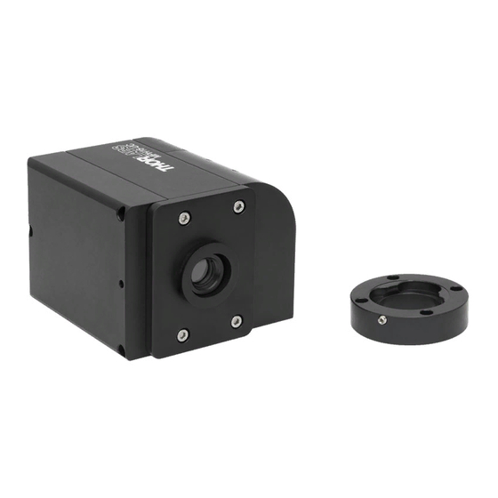
Chapter 6: Hardware Setup and Installation 6.3. Installation The MPH16-UC is ideally suited for integration with Thorlabs confocal laser scanning microscopes. For standalone systems, the MPH16-UC can be mounted using the included dovetail adapter. It is compatible with the 30 mm Thorlabs Cage System. - Page 28 SPW801 spanner wrench to expose internal SM05 threading, which is compatible with Ø1/2" lens tubes. ● 4-40 Tapped Holes: the outer aperture has four 4-40 tapped holes, which are compatible with the 16 mm Thorlabs Cage System. Page 24 TTN202954-D02...
-
Page 29: Chapter 7 Alignment
7.1. Laser Source Alignment Verify the gross alignment of the laser source through the MPH16-UC emission port. Place an iris between the laser source and the MPH16-UC input to align the laser with the optical axis of the pinhole wheel. -
Page 30: Mph16-Uc Fine Manual Alignment
Switch off the laser source and remove the translucent material (tape) from the emission port. 7.2. MPH16-UC Fine Manual Alignment WARNING DO NOT adjust the pinhole size using software before performing the laser alignment. This may damage the motorized pinhole through exposition to focused laser beam. - Page 31 Motorized Pinhole Wheel, Uncoated Chapter 7: Alignment Beams That Require Adjusted Beam Adjustments To achieve a round beam of maximum intensity, adjust both lens and pinhole wheel. Pinhole Wheel Alignment: use the +/- button in the MPH16 Pinhole Control window to rotate the pinhole wheel in both directions until you achieve a maximum beam brightness on the white cardboard / white printer paper.
-
Page 32: Lens Alignment
Repeat Step 3 until you align the smallest pinhole size (25 μm). Note: For optimal alignment, use a power meter (not included with the MPH16-UC unit) to measure the transmitted beam intensity. Adjust the pinhole wheel and lens alignment for maximum reading on the power meter. - Page 33 Motorized Pinhole Wheel, Uncoated Chapter 8: Maintaining the MPH16-UC Chapter 8 Maintaining the MPH16-UC Protect the MPH16-UC from adverse weather conditions. The MPH16-UC is not water resistant. The unit does not need regular maintenance. If you suspect a problem with the MPH16-UC, please contact Thorlabs at Phone: 973-300-3000 or Email: techsupport@thorlabs.com for assistance from an applications engineer.
- Page 34 Motorized Pinhole Wheel, Uncoated Chapter 9: Specifications Chapter 9 Specifications 9.1. General Specifications Specifications Value 3.73" x 3.34" x 2.60" Module Dimension (94.8 mm x 84.7 mm x 66.0 mm) Weight 1.0 kg Operating Voltage 24 VDC, 1.67 A Maximum Input Power 200 mW/cm Control USB, Software, and SDK included...
- Page 35 Motorized Pinhole Wheel, Uncoated Chapter 9: Specifications 9.3. Pinhole Wheel Specifications 18° Ø2.00" (Ø50.8 mm) Ø0.0020" (Ø0.050 mm) 90° Ø0.0038" (Ø0.10 mm) 100 µm Hole with a 50 µm Blocked Center Dot Ø0.10" at the Four A Positions (Ø2.5 mm) 3 Holes Cut Ø0.31"...
- Page 36 Motorized Pinhole Wheel, Uncoated Chapter 9: Specifications 9.4. Achromatic Doublet Specifications Specifications Value Focal length 75.0 mm Size Ø12.7 mm Page 32 TTN202954-D02...
- Page 37 Motorized Pinhole Wheel, Uncoated Chapter 10: Mechanical Drawing Chapter 10 Mechanical Drawing Figure 10–1 Pinhole Controller Rev B, February 21, 2021 Page 33...
- Page 38 Motorized Pinhole Wheel, Uncoated Chapter 10: Mechanical Drawing Figure 10–2 Detail Figure 10–3 Included Dovetail Adapter for 30 mm Cage System Compatibility Page 34 TTN202954-D02...
- Page 39 Motorized Pinhole Wheel, Uncoated Chapter 11: Certifications and Compliance Chapter 11 Certifications and Compliance Rev B, February 21, 2021 Page 35...
- Page 40 Waste Treatment is Your Own Responsibility If you do not return an “end of life” unit to Thorlabs, you must hand it to a com- pany specialized in waste recovery. Do not dispose of the unit in a litter bin or at a public waste disposal site.
- Page 41 Motorized Pinhole Wheel, Uncoated Chapter 13: Thorlabs Worldwide Contacts Chapter 13 Thorlabs Worldwide Contacts For technical support or sales inquiries, please visit us at www.thorlabs.com/contact for our most up-to-date contact information. USA, Canada, and South America UK and Ireland Thorlabs, Inc.
- Page 43 www.thorlabs.com...
Need help?
Do you have a question about the MPH16-UC and is the answer not in the manual?
Questions and answers