Table of Contents
Advertisement
Quick Links
Advertisement
Table of Contents

Related Manuals for THORLABS Vytran FFS2000 Series


Summary of Contents for THORLABS Vytran FFS2000 Series
- Page 1 FFS2000 Series Fiber Splicer User Guide...
-
Page 2: Table Of Contents
FFS2000 Series Table of Contents Chapter 1 Warning Symbol Definitions .................... 1 Chapter 2 Safety ............................ 2 Chapter 3 Description ........................... 4 3.1. Introduction ........................4 3.2. System Overview ......................4 3.2.1. Gas Supply ..........................4 3.2.2. Computer ..........................5 3.3. ... - Page 3 FFS2000 Series 5.10. Movement Control Bar ....................23 5.11. Status Bar ........................25 5.12. Initialization and Shutdown ..................25 5.13. Failure ..........................25 5.14. Splice Properties ......................26 5.14.1. M ulti Stage Splice Properties ....................27 Chapter 6 Fiber Preparation ........................32 6.1. Loading the Fiber ......................32 6.2. ...
- Page 4 FFS2000 Series 8.5. Diagnostics ........................54 Chapter 9 Proof Test (Item #s FFS2000PT and FFS2000WS) ............56 9.1. Setting Up ........................56 9.2. Proof Testing ......................... 56 9.2.1. Loading the Fiber ........................ 56 9.2.2. Adjusting the Proof Test Cycle .................... 57 ...
- Page 5 FFS2000 Series 12.4. FFS2000PM Specifications ................... 81 12.5. FS2000WS Specifications ..................... 82 Chapter 13 Regulatory ...........................83 Chapter 14 Thorlabs Worldwide Contacts ..................86 ...
-
Page 6: Chapter 1 Warning Symbol Definitions
FFS2000 Series Chapter 1: Warning Symbol Definitions Chapter 1 Warning Symbol Definitions Below is a list of warning symbols you may encounter in this manual or on your device. Symbol Description Direct Current Alternating Current Both Direct and Alternating Current Earth Ground Terminal Protective Conductor Terminal Frame or Chassis Terminal... -
Page 7: Chapter 2 Safety
FFS2000 Series Chapter 2: Safety Chapter 2 Safety All statements regarding safety of operation and technical data in this instruction manual will only apply when the unit is operated correctly. SHOCK WARNING Unplug the power cord before servicing the unit. Do not operate the unit without all covers and items properly installed. - Page 8 FFS2000 Series Chapter 2: Safety WARNING This unit must not be operated in explosive environments. The equipment should be used in a standard laboratory environment with temperature and humidity control. WARNING Acrylate can be wiped using Kimwipes and Acetone. All chemicals should be disposed of with chemical waste.
-
Page 9: Chapter 3 Description
(techsupport@thorlabs.com) as they are best qualified for diagnosing problems. Improper and/or incomplete maintenance may result in impairment of the operating characteristics of your splicer. 3.2. System Overview 3.2.1. Gas Supply Use only zero- or research-grade argon gas supply. Any other gas may damage the unit. Zero-grade argon is specified as 99.999% pure with O... -
Page 10: Computer
FFS2000 Series Chapter 3: Description Use only a Thorlabs-supplied gas line to interconnect the regulator to the splicing system. If an extended length gas line is required between regulator and splicer, please contact Thorlabs for purity requirements and line specifications. -
Page 11: System Overview
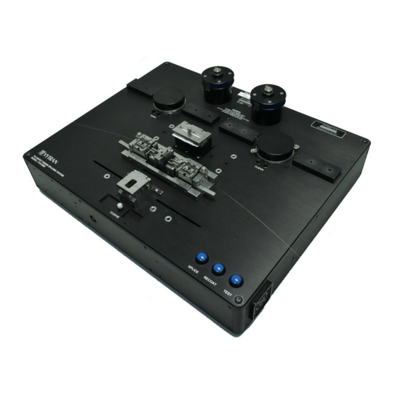
FFS2000 Series Chapter 3: Description 3.5. System Overview The splicer workstation (splicer) is the main component of the FFS2000 Series splicing system. It performs all the splicing process steps: soaking, stripping, cleaving, cleaning, splicing, recoating, and proof testing. The PC and gas supply, as well as peripheral components such as an optical power meter, are connected to the splicer back panel. -
Page 12: Standard Fiber Holding Block (Item #S Ffs2000 And Ffs2000Pt)
Groove inserts and top inserts are purchased separately; if purchased with an FFS2000PM base unit they will have been installed and factory aligned. Various sizes are available to support a range of coating diameters; for details please see Chapter 12. Replacements can be purchased from www.thorlabs.com and can be installed by the end user. -
Page 13: Rotary Fiber Holding Block For Pm Alignment (Item #S Ffs2000Pm And Ffs2000Ws)
FFS2000PM base unit they will have been installed and factory aligned. Various sizes are available to support a range of coating diameters; for details please see Chapter 12 Specifications. Replacements can be purchased from www.thorlabs.com and can be installed by the end user. -
Page 14: Strip And Cleave Station
FFS2000 Series Chapter 3: Description Figure 5 Soak Station Dunking Jig: The dunking jig is used to mount the fiber holding blocks at the soaking station. Vacuum is turned on when a FHB is inserted into the dunking jig in horizontal position. Vacuum turns off when dunking jig is raised to immerse the fiber in the solvent (max. - Page 15 FFS2000 Series Chapter 3: Description Figure 6 Strip Station Stripping Slot: The stripping slot is used to position the FHB at the stripping station. Positioning a FHB in the slot automatically activates the internal vacuum, pulling the fiber into the FHB and TMS V-groove. Simultaneously the TMS blades warm up to their preset stripping temperature.
-
Page 16: Clean Station
FFS2000 Series Chapter 3: Description Figure 7 Cleave Station Cleave Bushing: The cleave bushings are used to position the FHB at the cleaving station. Cleave Blade: The polycrystalline diamond cleave blade is used to score the fiber during the tension- and-scribe cleaving process. -
Page 17: Splice Station
FFS2000 Series Chapter 3: Description Dunking Jigs: The dunking jig are used to mount the fiber holding blocks at the cleaning station. Vacuum is turned on when a FHB is inserted into the dunking jig in horizontal position. Vacuum turns off when dunking jig is raised to immerse the fiber in the solvent (max. -
Page 18: Recoat Station
FFS2000 Series Chapter 3: Description Splice Station with PM Alignment (Item #s FFS2000PM and FFS200WS) Figure 10 Rotary Splice Station Splice Head: The splice head contains the tungsten or iridium filament, viewing optics, and XY illuminators. It moves axially during the high-strength fire polishing process. ... -
Page 19: Proof Test Station (Item #S Ffs2000Pt And Ffs2000Ws)
FFS2000 Series Chapter 3: Description Figure 11 Recoat Station Injection Port: The injection port is used to inject the UV acrylate into the mold cavity. Viewport: The viewport allows the user to watch the UV acrylate as it flows into the mold cavity. ... - Page 20 FFS2000 Series Chapter 3: Description Mandrel: During the proof test, the fiber is wrapped around the mandrels. The right mandrel will rotate, applying tension to the fiber. Clamp: The clamps hold the fiber taut between the mandrels and keep it from slipping during the proof test.
-
Page 21: Chapter 4 Setup
FFS2000 Series Chapter 4: Setup Chapter 4 Setup 4.1. Initialize The FFS2000 Series workstations accept an AC input range of 85 to 265 VAC, 47-63 Hz. Internally, the power supply senses the AC voltage being supplied and adjusts automatically. Connect the power cord (wall cord), four-pin external DC power cable between the power supply and the workstation, the Argon gas line, external vacuum line, and both the serial and camera PC interface cables to the back panel. -
Page 22: Chapter 5 Software
FFS2000 Series Chapter 5: Software Chapter 5 Software 5.1. Software Interface The GUI is the main window when working on the FFS2000 Series. It has different menus and toolbars that are explained further later in this document. The buttons are described from top to bottom. The FFS3 graphical user interface is illustrated below. -
Page 23: File
FFS2000 Series Chapter 5: Software 5.2.1. File Open: Open a new splice data file. Save: Save the current splice parameters to the current splice data file. Save As: Save the current splice parameters to a new splice data file. Database Options: Enables, Disables, or Resets the Database. The database has preconfigured settings that should not be altered. -
Page 24: Fiber Preparation
FFS2000 Series Chapter 5: Software 5.2.4. Fiber Preparation Allows access to the Soak, Clean, and Strip parameters. Figure 17 Fiber Preparation Menu 5.2.5. Splice The Splice Menu gives the user access to all of the parameters used in splicing. Additionally, the Splice Menu provides access to the User Macro paths. Figure 18 Splice Menu Rev B, July 21, 2017... -
Page 25: Proof Test
FFS2000 Series Chapter 5: Software 5.2.6. Proof Test Allows adjustment of the proof test parameters. Figure 19 Proof Test Menu 5.2.7. Recoat Allows the user to adjust the recoater cure duration. Figure 20 Recoat Menu 5.2.8. Reset The Reset menu allows the user to initialize, stop, and reset the unit. 5.2.9. -
Page 26: Camera Toolbar
Macro Toolbar The Macro Toolbar contains buttons that execute various macros. Note that it is possible to make buttons for single line commands in the macro bar as well as buttons for entire macros. Please contact Thorlabs for assistance. 5.7. - Page 27 Save: Saves the parameters currently in use to a data file that can be accessed later. In the case you are using an XML file provided by Thorlabs, it is recommend that you perform a “Save As” so that the standard file can be referenced in the future.
-
Page 28: Camera Image
FFS2000 Series Chapter 5: Software 5.9. Camera Image The camera image shown below is a side view (“Front” or “Back”) of a pair of fibers. Figure 25 Example of a Side View The pixels are compressed so that the entire image fits in the window. This becomes apparent when the end of a fiber is imaged and appears elliptical rather than circular. - Page 29 FFS2000 Series Chapter 5: Software The “Right Pivot” box enables the user to move the right fiber for alignment in the front view. There is an identical box for “Left Pivot” to move the left fiber for alignment in the front view. The “Right Rotation”...
-
Page 30: Status Bar
FFS2000 Series Chapter 5: Software 5.11. Status Bar Figure 26 Status Bar This window indicates the status of the unit. When the bottom bar is green and the window reads “Ready,” the unit is ready to execute new commands. When the top bar is red, the unit is not responding, and is either busy or needs to be initialized. -
Page 31: Splice Properties
FFS2000 Series Chapter 5: Software Figure 27 Failure Process Window If you press reset then the reset macro will run. On completion you can choose to “abort or retry or continue”. 5.14. Splice Properties To customize the splice parameters, go to Splice → Splice Parameters. ... -
Page 32: Multi Stage Splice Properties
FFS2000 Series Chapter 5: Software 5.14.1. Multi Stage Splice Properties Enabling the Multi Stage Splice Process Figure 29 Activating Multi-Stage Splice Go to Splice → Splice Parameters. The normal default is for Multi Stage Splice to be disabled. Check the Multi Stage Splice check box as shown in Figure 29. - Page 33 FFS2000 Series Chapter 5: Software Figure 31 Adding Stages The parameters that may be set are: Parameter Icon Parameter Description Splice stage name: <Label> The argon flow rate for the splice process. The splice time in seconds. The splice power in watts. The velocity at which the fibers are pushed together during fusion.
- Page 34 FFS2000 Series Chapter 5: Software Figure 32 Sample Stage Any number of splice stages may be added. Click Add Step to add a second stage as shown in Figure 33. Add as many heating, cooling, and pushing stages as are required. Figure 33 Sample Stage 2 ...
- Page 35 FFS2000 Series Chapter 5: Software Figure 34 Setting the .xslt File path To select the correct XSLT file, open the XSLT splice file tab. This file path will be saved into the splice data file so that once selected, a splice file is always linked to the correct XSLT file unless the operator changes the splice file.
- Page 36 FFS2000 Series Chapter 5: Software Figure 35 Disabling Multi-Stage Splice Figure 36 Setting .xslt to Default Path Rev B, July 21, 2017 Page 31...
-
Page 37: Chapter 6 Fiber Preparation
FFS2000 Series Chapter 6: Fiber Preparation Chapter 6 Fiber Preparation Before preparing the fiber make sure that the splicer workstation meets the following criteria: Individual stations of the splicer are prepared, and all surfaces are clean. The inserts in the FHBs, the Graphite V-Grooves, and Cleave Inserts are of the appropriate size for the fiber to be spliced. -
Page 38: Coating Removal
The soak time will need to be set to prevent the chemical agent from ‘wicking’ too far up inside the Jacket of the Fiber, and the appropriate settings can only be determined through experimentation depending upon the type of chemical agent employed and the particular fiber. Contact Thorlabs for assistance if required. -
Page 39: Soaking Procedure (Chemo-Mechanical Only)
FFS2000 Series Chapter 6: Fiber Preparation The thermo-mechanical stripping method uses heat to soften the acrylate coating. A heating element is incorporated in the bottom V-groove insert at the stripping station. The heating element is kept at a low background temperature at all times, which for some fibers (such as SMF-28) is sufficient to strip the coating almost immediately. -
Page 40: Stripping Procedure
FFS2000 Series Chapter 6: Fiber Preparation Figure 38 Soaking Procedure Once the dunking jig has been raised the vacuum will shut off and the Soak Right Indicator of the GUI will highlight red. The indicators will remain in this state for the preset soak time. After the soak time has elapsed, the right soak indicator lamp on the splicer workstation will light red, and the Soak Right Indicator of the GUI will highlight green. - Page 41 Slide the FHB away from the stripper/cleaver block. Use a smooth, even sliding action to strip the coating to the proper length. For different cladding diameters than those listed here, please contact Thorlabs Technical Support. TMS blade inserts are available for cladding diameters up to Ø200 µm upon request.
-
Page 42: Diagnostics
If such a silicone buffered fiber is stripped, the residue should be dissolved using an appropriate silicone solvent and properly rinsed before cleaving the fiber. Thorlabs can suggest manufacturers of suitable silicone solvents that may be appropriate. - Page 43 FFS2000 Series Chapter 6: Fiber Preparation Problem Possible Cause Solution Excessive fiber curl due to Physically straighten the fiber/buffer and apply residual deformation of the heat to relax the residual buffer deformation. buffer material. Coating is difficult to Soaking solution not full. The soaking container must be filled to within 1/4"...
-
Page 44: Cleaning The Fiber
FFS2000 Series Chapter 6: Fiber Preparation Problem Possible Cause Solution Heating time too long. If the fiber is pre-soaked, a long heating time may dry out the soft buffer making it difficult to remove. To avoid this the fiber should be stripped as soon as possible after the heating element reaches the proper temperature (indicator on steadily) or the Boost Current should be reduced. -
Page 45: Diagnostics
Cleave operation commences. This should already be setup for your workstation. Refer to the maintenance section or contact Thorlabs if you require further advice on this. Note: Parameter changes in the software interface are not saved into the configuration file (*.xml) until a file save is executed. -
Page 46: Diagnostics
Please contact Thorlabs for assistance. Blade rubs along the FHB is slipping due to dirty FHB Clean the FHB V-grooves and top cap with fiber without cleaving. - Page 47 Cleave tension is insufficient Increase the cleave tension. (check for FHB slippage; see above). Cleave blade height adjustment Please contact Thorlabs for instructions. may be required The FHB cocks forward The bottom of the FHB or the Scrub with toothbrush provided.
-
Page 48: Chapter 7 Splicing The Fiber
7.2. Setting Up During purchasing Thorlabs personnel will have advised on your application and configured Splice Files to suit. Be sure to have the appropriate Splice File loaded for the fiber combination to be processed. Rev B, July 21, 2017... -
Page 49: Splice Settings
FFS2000 Series Chapter 7: Splicing the Fiber 7.2.1. Splice Settings Splice Parameters: Check the parameters of the ‘Splice Parameters’ in the ‘Splice’ menu of the GUI under Splice Parameters. Refer to the table below for typical values. Parameter Fiber Diameter 80 µm 125 µm Pre-Gap... -
Page 50: Loading The Fibers
FFS2000 Series Chapter 7: Splicing the Fiber When both, the right- and left-hand fibers have been prepared for splicing (see Chapter 6), open the Splice Cap and locate the FHBs in their respective positions on the Transfer Jig. The Cleave Lever should be in the released, or back, position. - Page 51 FFS2000 Series Chapter 7: Splicing the Fiber Figure 45 Load Fiber Dialog Note: Do NOT use the Splice command, as it will execute a splice immediately without allowing the operator to load the fiber. Load the fibers by carefully placing the transfer jig with its pins into the bushings. Make sure to guide the transfer jig during the placement so that the fibers don’t touch any components of the splicing station besides the Graphite V-groove inserts.
-
Page 52: Splice Routine
FFS2000 Series Chapter 7: Splicing the Fiber To continue the One Button Splice Process, click OK in the “load fiber dialog” or press the Splice Button on the workstation again. The activated splice routine consists of multiple sub-processes that are defined within the Splice Process Editor. -
Page 53: Guidelines For Achieving A High Strength Splice
FFS2000 Series Chapter 7: Splicing the Fiber increase to splice levels for about 3 seconds to clean the system of any impurities and purge the Splice Head of remaining oxygen. The Splice Head will then move the View To Splice Distance so that the filament is centered on the fibers (assuming no Splice Offset is set). -
Page 54: Diagnostics
This causes an increase in silica deposits on the fiber, which can’t be completely removed during the fire polish step. The result will be decreased splice strengths. Thorlabs personnel can advise on the correct methods of performing splices to avoid this issue. - Page 55 FFS2000 Series Chapter 7: Splicing the Fiber Problem Possible Cause Solution Splice loss drops Filament power is too high. Run filament normalization. System will instantly, then slowly automatically optimize power level and view-to- increases. splice distance. Filament has aged. Run filament normalization. System will automatically optimize power level and view-to- splice distance.
-
Page 56: Chapter 8 Recoat
WARNING Prior to handling the UV acrylate material, be sure to read the Material Safety Sheet for your material. MSDS for UV acrylate material purchased from Thorlabs can be found by visiting www.thorlabs.com and searching for the Thorlabs’ Item #. -
Page 57: Priming The Remote Manual Injection System
FFS2000 Series Chapter 8: Recoat 8.3. Priming the Remote Manual Injection System The following procedure is required to prime the remote manual injection system: 1. Make sure to have lens tissue and cleaning solution (acetone or alcohol) available prior to proceeding. 2. -
Page 58: Fiber Recoating Procedures
FFS2000 Series Chapter 8: Recoat 7. Watch the injection port for signs of recoat material. Make sure to collect the recoat material as it comes out of the mold injection port. Do not allow recoat material to run down the face of the mold and under the mold plate. -
Page 59: Diagnostics
Thorlabs Item # RM280 mold assembly with high-index Thorlabs Item # AB950200 recoat material to 30 - 60 seconds with the low-index Thorlabs Item # PC373 recoat material. If you would like to use the low-index material with your FFS2000 series system, we recommend contacting Thorlabs for assistance. - Page 60 It may be necessary to coat the mold plates with lift easily or recoated recoat plate and/or top. a release agent prior to recoating. Contact section adheres Thorlabs for release agent recommendations and instructions for use. tightly to mold plate. Fiber sticks to recoat Recoat mold plates are dirty.
-
Page 61: Chapter 9 Proof Test (Item #S Ffs2000Pt And Ffs2000Ws)
FFS2000 Series Chapter 9: Proof Test (Item #s FFS2000PT and FFS2000WS) Chapter 9 Proof Test (Item #s FFS2000PT and FFS2000WS) The proof testing station of the FFS2000PT or FFS2000WS can be used to determine the breaking strength of a fiber or to ensure that a fusion spliced fiber meets a minimum strength requirement. The section of fiber to be tested is located between two mandrels. -
Page 62: Adjusting The Proof Test Cycle
After failed proof tests, clean up glass debris, as this can cut the skin. Any glass debris should be disposed of in a glass waste container, such as Thorlabs’ Item # FTDU. Figure 49 Proof Test Mandrels and Fiber Splice in Test Position 9.2.2. -
Page 63: Proof Testing
FFS2000 Series Chapter 9: Proof Test (Item #s FFS2000PT and FFS2000WS) Figure 50 Schematic of Proof Test Load Ramp-Rate Adjustment 9.2.3. Proof Testing CAUTION Always use the safety shield or wear safety glasses when proof or tension testing fiber. The fiber under test can shatter and send glass particles flying. -
Page 64: Diagnostics
Proof test grips are dirty. Clean proof test grips with a cotton levels. swab dipped in alcohol. Proof test grips are work out. Contact Thorlabs to order replacements. An additional fiber wrap around the When proof testing at high tension mandrel may be required. -
Page 65: Chapter 10 Shutting Down And Storage
FFS2000 Series Chapter 10: Shutting Down and Storage Chapter 10 Shutting Down and Storage 10.1. Shutting Down The following procedures should be followed when shutting down the FFS2000 Series system: Turn off the power to the splicer (i.e., ON/OFF switch on the back panel) and the external power supply, and shut down the FFS3 software. -
Page 66: Chapter 11 Maintenance
FFS2000 Series Chapter 11: Maintenance Chapter 11 Maintenance 11.1. Planned Maintenance The FFS2000 Series is designed for a production environment to give trouble free operation provided normal planned maintenance is adhered to. Maintenance and repair procedures should only be performed by trained personnel. -
Page 67: Change / Remove Fhb Inserts
FFS2000 Series Chapter 11: Maintenance If the vacuum ports at the bottom of the V-groove appear plugged it may be necessary to remove the inserts so they can be “blown clean” from behind. If necessary, a 0.002” plastic shim (red) from the shim kit can be used to clear the V-groove ports. -
Page 68: Adjust Cleave Tension
FFS2000 Series Chapter 11: Maintenance Figure 52 Change Rotary FHB Insert 11.2.3. Adjust Cleave Tension 1. Insert the FHB to be adjusted at the appropriate cleave position on the splicer. Note: Make sure to leave the cleave lever in its released position. 2. -
Page 69: Strip/Cleave Station
FFS2000 Series Chapter 11: Maintenance 11.3. Strip/Cleave Station 11.3.1. Inspect/Clean Cleave Inserts The cleave vacuum V-grooves, as well as the cleave top insert clamping surfaces, should be inspected regularly for dirt, debris and/or damage. Damage or dirt on these surfaces could cause the fiber to break at the insert when cleave tension is applied. -
Page 70: Change/Align Tms Inserts
Note: Changing strippers means changing the entire TMS insert (both top and bottom). Do not attempt to adjust the blades at the ends of the TMS insert. The stripper blades are precision-aligned at Thorlabs. Any misalignment will result in poor stripping performance and possibly fiber damage. - Page 71 FFS2000 Series Chapter 11: Maintenance Figure 56 Removing TMS Inserts Install New TMS Inserts 1. Position the bottom TMS insert such that the electrical contact pins line up with the two sockets in the bottom channel and the engraved fiber size faces forward. Carefully press the pins down into the sockets until the insert is flush with the stripper block surface.
-
Page 72: Inspect/Clean Cleave Blade
FFS2000 Series Chapter 11: Maintenance 11.3.5. Inspect/Clean Cleave Blade The diamond edge of the cleave blade should be regularly inspected for debris and/or damage that may result in sub-optimum cleave performance. For easier inspection and cleaning, the cleave blade can be advanced forward from its parked or “home”... -
Page 73: Check/Adjust Cleave Blade Forward Move
FFS2000 Series Chapter 11: Maintenance the blade is now at the top (see 11.3.8 ). If the blade has already been flipped, and two shims have already been added, then a new cleave blade must be installed. Apply downward pressure to the front plate assembly and retighten the clamping screws, securing the front plate. -
Page 74: Rotate/Replace The Cleave Blade
FFS2000 Series Chapter 11: Maintenance 1. Locate and open the appropriate cleave macro (blade cleaver right.txt or blade cleave left.txt) using either Windows Explorer (FFS directory) or by right clicking and opening the appropriate macro under the menu Splice | User Macro Path 1…. The third line of the macro will look like: MOTOREXSTEP (11 -2445)0 ;step forward for left cleave The first number in parentheses is the motor number;... -
Page 75: Replace Ionize Unit
Note: Do not discard the old unit. Place it in the supplied case and return to: NRD, Inc. 2937 Alt Boulevard Grand Island, New York 14072 USA Telephone: +1 (716) 773-7634 Contact Thorlabs for information regarding ionizing units. Page 70 TTN047338-D02... -
Page 76: Splice Station
FFS2000 Series Chapter 11: Maintenance Figure 60 Replace Ionizing Units 11.4. Splice Station 11.4.1. Clean Mirror Standard Mirror (Item #s FFS2000 and FFS2000PT) If the fiber image is distorted or pieces of dirt are visible on the mirror surface under 10-20X magnification, the mirror surfaces should be cleaned. -
Page 77: Check/Clean Graphite V-Grooves
FFS2000 Series Chapter 11: Maintenance To clean the 90° mirror, raise the splice top and flip the 90° end view mirror down. Wipe it with the cotton swab and lens cleaner using a single-direction stroke. Since it is harder to view, the 135° mirror must be cleaned with the aid of the image. Close the splice top to display the image from the 135°... - Page 78 FFS2000 Series Chapter 11: Maintenance Figure 63 Removing the Filament Locate the pink foam diffuser in the purge port of the filament channel (Figure 64). If the foam diffuser looks to be seated approximately 1/32" below the top of the filament channel, and does not appear to be damaged or dirty, proceed to step 13.
-
Page 79: Filament Calibration
FFS2000 Series Chapter 11: Maintenance 8. To replace the foam, it must first be compressed into a tight cylindrical shape. Pinching the foam tightly between two (clean) fingers, use the tweezers to roll it tightly into a cylinder. 9. Reinsert the foam into the gas orifice in its compacted form. Maneuver the foam so that it is 1/32" below the filament channel surface. -
Page 80: Remove/Align Recoat Assembly
FFS2000 Series Chapter 11: Maintenance illuminate when a bulb check is performed. Replace and align the recoat assembly. The bulb is RoHS compliant and can be disposed of in general waste or with other glass waste. 11.5.2. Remove/Align Recoat Assembly 1. -
Page 81: Flush Recoat System
FFS2000 Series Chapter 11: Maintenance Figure 66 Align Recoat Mold 11.5.3. Flush Recoat System The recoat pumping system should be flushed clean every 6 months as part of the recoat material replacement procedure. Before flushing the system, make sure to have lens tissue and cleaning solution (acetone or alcohol) available prior to proceeding. -
Page 82: Soak / Clean Station
Figure 67 Flushing the Recoat System 11.6. Soak / Clean Station 11.6.1. Replace Indicator Bulb Unscrew the red indicator cap, and remove the bulb. Replace only with a Thorlabs supplied or recommended bulb. Replace the indicator cap. 11.6.2. Replace Solvents WARNING Danger of shock and damage to the unit if it is left connected to the power supply! Turn off power, and disconnect the power supply. - Page 83 FFS2000 Series Chapter 11: Maintenance Figure 68 Replace Soaking Solvent Cleaning Station: The cleaning container is wired into the unit, and must be removed carefully. Tightly screw on the top of the cleaning container. While pushing down on the container top, unscrew the flange clamps ½ turn to release the container (Figure 69).
-
Page 84: Proof Test Station
FFS2000 Series Chapter 11: Maintenance 11.7. Proof Test Station 11.7.1. Replace Proof Test Grip Remove the 4 flat head screws on top of the proof test mandrel and lift off the flanged top. Depress the mandrel clamp button and remove the rubber grip. Install a new grip making sure that the grip is uniformly positioned around the mandrel and seated below the bottom flange. -
Page 85: Chapter 12 Specifications
Tension can be adjusted manually by the user for different fiber sizes. The cleaver is calibrated using standard weights that are hung off a pulley, so the tension settings are programmed in grams. This maximum tension corresponds to 250 g. Depending on your selection of Recoat Mold Assembly (sold separately on www.thorlabs.com). Page 80... -
Page 86: Ffs2000 Specifications
FFS2000 Series Chapter 12: Specifications 12.2. FFS2000 Specifications Fiber Specifications Accepted Fiber Cladding 80 to 200 µm Diameters Fiber Type SM or MM 12.3. FFS2000PT Specifications Fiber Specifications Accepted Fiber Cladding 80 to 200 µm Diameters SM or MM Fiber Type Proof Testing Maximum Tension 89 N (20 lbs) -
Page 87: Fs2000Ws Specifications
FFS2000 Series Chapter 12: Specifications 12.5. FS2000WS Specifications Fiber Specifications Accepted Fiber Cladding 80 to 200 µm Diameters Fiber Type SM, MM, or PM PM Rotation Specifications Rotation Alignment Fully Automated by End-View Alignment Technology or External Feedback Rotation Resolution Stepper Motor Controller (0.01°... - Page 88 FFS2000 Series Chapter 13: CE Certificate Chapter 13 CE Certificate Rev B, July 21, 2017 Page 83...
- Page 89 FFS2000 Series Chapter 13: CE Certificate Page 84 TTN047338-D02...
-
Page 90: Chapter 13 Regulatory
Waste Treatment is Your Own Responsibility If you do not return an “end of life” unit to Thorlabs, you must hand it to a company specialized in waste recovery. Do not dispose of the unit in a litter bin or at a public waste disposal site. -
Page 91: Chapter 14 Thorlabs Worldwide Contacts
FFS2000 Series Chapter 15: Thorlabs Worldwide Contacts Chapter 15 Thorlabs Worldwide Contacts USA, Canada, and South America UK and Ireland Thorlabs, Inc. Thorlabs Ltd. 56 Sparta Avenue 1 Saint Thomas Place, Ely Newton, NJ 07860 Cambridgeshire CB7 4EX Great Britain... - Page 92 www.thorlabs.com...
Need help?
Do you have a question about the Vytran FFS2000 Series and is the answer not in the manual?
Questions and answers