Table of Contents
Advertisement
Quick Links
Contents
Important User Information � � � � � � � � � � � � � � � � � � � � � � � � � � � � � � 2
Safety Precautions � � � � � � � � � � � � � � � � � � � � � � � � � � � � � � � � � � � � 2
Required Tools� � � � � � � � � � � � � � � � � � � � � � � � � � � � � � � � � � � � � � � � 3
Supplied Hardware � � � � � � � � � � � � � � � � � � � � � � � � � � � � � � � � � � � � 3
Visit the Tuba and Sousaphone Mobile Storage Rack web page at wengercorp.com for more information.
Note: Please read and understand these instructions before proceeding�
Note: If you need additional information, contact Wenger Corporation using the information below�
©Wenger Corporation 2024
Wenger Corporation, 555 Park Drive, P�O� Box 448, Owatonna, Minnesota 55060-0448
Questions? Call�����USA: (800) 4WENGER (493-6437) • Worldwide: +1-507-455-4100 • wengercorp�com
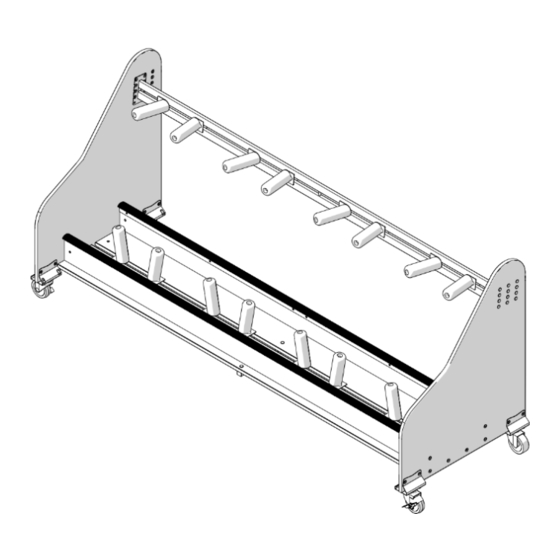
Tuba and Sousaphone
Mobile Storage Rack
Parts List � � � � � � � � � � � � � � � � � � � � � � � � � � � � � � � � � � � � � � � � � � � � 4
Assembly � � � � � � � � � � � � � � � � � � � � � � � � � � � � � � � � � � � � � � � � � � � � 5
Operation � � � � � � � � � � � � � � � � � � � � � � � � � � � � � � � � � � � � � � � � � � � � 15
Replacement Parts � � � � � � � � � � � � � � � � � � � � � � � � � � � � � � � � � � � � 16
Printed in USA 2024-10
Assembly Instructions
4-Unit Model Shown
Part #148J426-03
Advertisement
Table of Contents

Subscribe to Our Youtube Channel
Related Manuals for Wenger Tuba


Summary of Contents for Wenger Tuba
-
Page 1: Table Of Contents
Replacement Parts � � � � � � � � � � � � � � � � � � � � � � � � � � � � � � � � � � � � 16 Visit the Tuba and Sousaphone Mobile Storage Rack web page at wengercorp.com for more information. -
Page 2: Important User Information
Wenger Corporation� Wenger Corporation does not assume any responsibility for any errors that may appear in these instructions� In no event will Wenger Corporation be liable for technical or editorial omissions made herein, nor for direct, indirect, special, incidental, or consequential damages resulting from the use or defect of these instructions�... -
Page 3: Required Tools
Required Tools • Plastic mallet • 1/2" (13 mm) Open end wrench • Phillips head screwdriver or phillips head insert bit • 5/32" (4 mm) Hex insert bit or allen wrench (supplied) • Variable speed drill (to drive hex socket screws) •... -
Page 4: Parts List
Parts List Item Qty Description Item Qty Description Item Qty Description End Panel Bottom Rail Panel 8 mm x 25 mm Wood Dowel Swivel Caster Brake 1/4-20 Hex Cap Nut 1/4-20 Cross Dowel Swivel Caster 1/4-20 x 1�57" Machine Screw 3/8-16 x 1-3/4"... -
Page 5: Assembly
Assembly NOTICE This assembly procedure is shown using the 4-unit model, the procedure for the 3-unit model is similar. 1� Insert 8 x 25 mm wood dowels (19) into the larger holes in the bottom edge of both bottom rail panels (10)� (Detail A) Six dowels are used with the 4-unit model and four dowels are used with the 3-unit model�... - Page 6 Assembly (continued) 2� Assemble the two bottom support assemblies� a. Lay both bottom support panels (9) flat so the dowel holes are facing up. With a plastic mallet, pound an 1/4-20 insert nut (6) into the two center holes in both bottom support panels�...
- Page 7 Assembly (continued) 3� Attach one rack extrusion to each of the bottom support assemblies� a� Place one rack extrusion (8) over each bottom support assembly and align the sets of the pre-drilled holes� The rack extrusion must not extend beyond the edge of the bottom support assembly� (Detail C) b�...
- Page 8 Assembly (continued) 5� Attach the two bottom support assemblies to the end panels� Wood strips from the packaging can be used under the bottom support assemblies to raise them off of the floor for this step. a� Fit one 1/4-20 cross dowel (20) with the flat side facing to the inside and the slotted side facing to the outside into each end of both bottom support panels�...
- Page 9 For small tubas, the upper support weldment should be placed lower so it will be under the bell of the shortest instrument� Some experimentation may be required to find the best placement. Typical tuba or sousaphone Smaller tubas Detail F...
- Page 10 1/4-20 x �590 Machine screws (14) into the already installed 1/4-20 insert nuts on each side� (Detail G) The Wenger logo on the upper support weldment should face front� NOTICE To prevent scratching the end panels, two people should be used to position and attach the upper support weldment.
- Page 11 Assembly (continued) 7� Plug the remaining unused upper holes in both end panels by placing a 1/4-20 x �590 machine screw (14) into the insert nuts� (Detail H) Detail H 8� Pre-assemble the casters, two swivel brake casters (2) and two swivel casters (3) each to a caster mount bracket (4) using four 5/16-18 x 5/8"...
- Page 12 Assembly (continued) 9� Tip the storage rack onto the rear side� 10� Attach the caster assemblies� Swivel caster with brake Holes toward the inside Swivel caster a� Attach one swivel caster with brake to the front side of each end panel using one #8 x 5/8"...
-
Page 13: Machine Screw
Assembly (continued) 11� Attach the support bar (6) to the underside of the bottom support panels using four 1/4-20 x 1�57" machine screws (12) into the already installed insert nuts� (Detail L) Detail L 12� Assemble the cradles by sliding one 3/8-16 x 1-3/4" carriage bolt (21) into the square hole at the base of each cradle (5) as shown�... - Page 14 Assembly (continued) 13� Attach cradles (5) to the bottom of the storage rack� Two cradles are required for each instrument and should point away from each other in a "V" formation as shown� Attach each cradle using one 3/8 x 2" fender washer (15) and 3/8-16 wing nut (25)� (Detail N) Detail N 14�...
-
Page 15: Operation
Operation This storage rack has been designed to store multiple sizes of tubas, sousaphones or a combination of the two� Instruments should be placed so they lean slightly backwards against the cradles on the upper support weldment� Instruments should be placed on the bottom supports� Adjust the cradles by loosening the wing nuts and sliding each cradle to hold the instrument snuggly�... -
Page 16: Replacement Parts
Replacement Parts Item Qty Description Item Qty Description Item Qty Description End Panel Bottom Rail Panel 8 mm x 25 mm Wood Dowel Swivel Caster Brake 1/4-20 Hex Cap Nut 1/4-20 Cross Dowel Swivel Caster 1/4-20 x 1�57" Machine Screw 3/8-16 x 1-3/4"...
Need help?
Do you have a question about the Tuba and is the answer not in the manual?
Questions and answers