
Related Manuals for TRENDnet TEG-S224M


Summary of Contents for TRENDnet TEG-S224M
- Page 1 TEG-S224 Series Stackable NWay Ethernet Switch User’s Guide First Edition (Feb. 2000) Printed In Taiwan RECYCLABLE...
-
Page 2: Fcc Warning
FCC Warning This equipment has been tested and found to comply with the limits for a Class A digital device, pursuant to Part 15 of the FCC Rules. These limits are designed to provide reasonable protection against harmful interference when the equipment is operated in a commercial environment. -
Page 3: Table Of Contents
ABLE OF ONTENTS ABOUT THIS GUIDE..................X ......................ONVENTIONS ’ ............... VERVIEW OF THIS UIDE INTRODUCTION ....................1 ................1 THERNET ECHNOLOGY ..............2 IGABIT THERNET ECHNOLOGY ..................3 WITCHING ECHNOLOGY ......................... 4 EATURES Ports........................4 Performance features ..................5 Management ......................6 UNPACKING AND SETUP ................7 ...................... - Page 4 WITCH TO UB OR WITCH 10BASE-T Device....................26 100BASE-TX Device..................27 SWITCH MANAGEMENT CONCEPTS ............28 ............... 28 OCAL ONSOLE ANAGEMENT Diagnostic (Console) Port (RS-232 DCE) ...........29 IP A SNMP C ..........29 DDRESSES AND OMMUNITY AMES ........................30 RAPS ........................32 ..................33...
- Page 5 Configure Static Forwarding Table Entry..........81 Configure MAC Address Filtering............82 Configure Permanent Multicast Filtering..........83 Configure IGMP ..................84 Configure VLANs & MAC-based Broadcast Domains ........88 Configure MAC-based Broadcast Domains.......... 90 Configure IEEE 802.1Q VLANs............... 93 Update Firmware and Configuration Files..........98 Special Note Concerning Firmware Updates...........
- Page 6 Traffic Statistics ....................107 Port Utilization................... 107 Port Traffic Statistics................. 108 Port Packet Error Statistics ..............110 Port Packet Analysis Statistics............... 112 Browse Address Table ..................113 Switch History ....................114 Browse IGMP Status..................115 ................... 117 ESETTING THE WITCH Restart System....................
- Page 7 Switch History ....................169 Maintenance....................169 Firmware and Configuration Update............... 170 Save Settings To TFTP Server ................ 171 Save Switch History To TFTP Server ............172 Save Changes ....................173 Factory Reset ....................174 Restart System ....................175 TECHNICAL SPECIFICATIONS ..............176 RJ-45 PIN SPECIFICATION ...............
- Page 8 Figure 3-11. The Switch LED indicators ............22 Figure 4-1. Switch connected to an End Node ..........25 Figure 4-2. Switch connected to a n ormal (non-Uplink) port on a hub or switch using a straight or crossover cable............26 Figure 5-1.
- Page 9 Figure 6-10. Switch Stack Configuration screen..........65 Figure 6-11 Information of Individual Switch Unit screen ......66 Figure 6-12. Configure Advanced Switch Features screen......67 Figure 6-13. Port Configuration screen ............68 Figure 6-14. Port Trunk screen ................71 Figure 6-15. Port Mirroring Configuration screen......... 73 Figure 6-16.
- Page 10 Figure 7-7. Port Mirroring window..............131 Figure 7-8. STP Parameter Setting window............133 Figure 7-9. Spanning Tree Custom Setting window........134 Figure 7-10. Configure Forwarding Table And Filtering Table window .136 Figure 7-11. Static Forwarding Table window..........137 Figure 7-12. Static Forwarding Table---Edit window ........138 Figure 7-13.
- Page 11 Figure B-1. The standard RJ-45 receptacle/connector........180 Table B-1. The standard Category 3 cable, RJ-45 pin assignment....181 Figure B-2. Straight cable for Switch (uplink MDI-II port) to switch/Hub or other devices connection ..................181 Figure B-3. Crossover cable for Switch (MDI-X port) to switch/hub or other...
-
Page 12: About This Guide
Explorer, 4.x or later, are recommended). Conventions References in this manual to the TEG-S224 Series are frequently written simply as “Switch” or “Switches” where the text applies to all models. Model numbers are normally used only to differentiate among specific Switches where necessary. - Page 13 Console Management via the RS-232 DCE console port and other aspects about how to manage the Switch. Chapter 6, Using the Console Interface. Tells how to use the built-in console interface to change, set, and monitor Switch performance and security.
-
Page 15: Introduction
Stackable NWay Ethernet Switch User’s Guide NTRODUCTION This section describes the features of the Switch, as well as giving some background information about Ethernet/Fast Ethernet, Gigabit Ethernet, and switching technology. Fast Ethernet Technology The growing importance of LANs and the increasing complexity of desktop computing applications are fueling the need for high performance networks. -
Page 16: Gigabit Ethernet Technology
Likewise, since data transfers occur 10 times faster than Fast Ethernet, servers outfitted with Gigabit Ethernet NIC’s are able to perform 10 times the number of operations in the same amount of time. In addition, the phenomenal bandwidth delivered by Gigabit Ethernet is the most cost-effective method to take advantage of today and tomorrow’s rapidly improving switching and routing internetworking... -
Page 17: Switching Technology
A switch increases capacity and decreases network loading by making it possible for a local area network to be divided into different segments which don’t compete with each other for network transmission capacity, giving a decreased load on each. -
Page 18: Features
Features The TEG-S224 series of Switches can include one master (either a TEG-S224M or a TEG-S224MF) and up to three clients (TEG-S224S or TEG-S224SF). They are designed for easy installation and high performance in an environment where traffic on the network and the number of users increases continuously. -
Page 19: Performance Features
PC and Console/Out-of-band management (TEG-S224M or TEG-S224MF only). One slide-in module interface in the front panel for 1 or 2 ports 10/100M Ethernet connection. Three optional modules are available: 2-port TX, 2-port FX (MT-RJ), and 1-port FX (SC). -
Page 20: Management
Stackable NWay Ethernet Switch User’s Guide Data filtering rate eliminates all error packets, runts, etc. at 14,880 pps per port at 100% of wire-speed for 10Mbps speed. Data filtering rate eliminates all error packets, runts, etc. at 148,800 pps per port at 100% of wire-speed for 100Mbps speed. -
Page 21: Unpacking And Setup
Mounting kit: two mounting brackets and screws Four rubber feet with adhesive backing One AC power cord This user’s guide on CD-ROM with a Registration Card If any item is found missing or damaged, please contact your local reseller for replacement. Unpacking and Setup... -
Page 22: Setup
Stackable NWay Ethernet Switch User’s Guide Setup The setup of the Switch can be performed using the following steps: The surface must support at least 5 kg. The power outlet should be within 1.82 meters (6 feet) of the device. -
Page 23: Rack Installation
Figure 2-1. Switch installed on a Desktop or Shelf Rack Installation The Switch can be mounted in an EIA standard size, 19-inch rack, which can be placed in a wiring closet with other equipment. To install, attach the mounting brackets on the switch’s front panel (one on each side) and secure them with the screws provided. -
Page 24: Power On
Figure 2-2B. Installing the Switch in an equipment rack Power on The Switch can be used with AC power sources 100 - 240 VAC, 50 - 60 Hz. The power switch is located at the rear of the unit adjacent to the AC power connector and the system fan. -
Page 25: Power Failure
The 100M LED indicator may remain ON or OFF depending on the transmission speed. Power Failure As a precaution, the Switch should be unplugged in case of power failure. When power is resumed, plug the Switch back in. Unpacking and Setup... -
Page 26: Identifying External Components
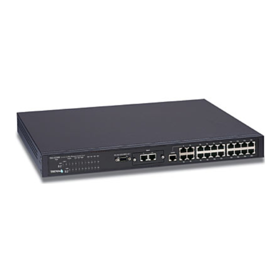
LED indicators of the Switch Front Panel The front panel of the Switch consists of either 19 or 20 (10/100 Mbps) Ethernet/Fast Ethernet ports, one or two uplink jacks, a slide- in module slot for 10/100 Mbps Ethernet ports, an RS-232 communication port (TEG-S224M and TEG-S224MF only), and LED indicators. -
Page 27: Rear Panel
Switch and status of the network. A description of these LED indicators follows (see LED Indicators). An RS-232 DCE console port is used to diagnose the Switch via a connection to a PC and Local Console Management (TEG- S224M and TEG-S224MF only). -
Page 28: Side Panels
Supported input voltages range from 100 ~ 240 VAC at 50 ~ 60 Hz. Side Panels The right side panel of the Switch contains two system fans (see the bottom part of the diagram below). The left side panel contains heat vents. -
Page 29: Stack Operation
Stack Operation The TEG-S224M and the TEG-S224MF are intelligent Switches capable of acting as a master for up to three client Switches (TEG- S224S and TEG-S224SF). Each port is referred to by unit ID and port number in your TEG-S224 Series stack. -
Page 30: Figure 3-4. Switch Stack With One Master And Three Clients
Stackable NWay Ethernet Switch User’s Guide TEG-S224M TEG-S224S Figure 3-4. Switch stack with one master and three clients Please note that two client switches can also be connected via the Stacking input/output ports. The following diagram displays some possible switch stack connections:... -
Page 31: Optional Plug-In Modules
Local 10Mbps printer Figure 3-5. Switch stack with example of possible connections Optional Plug-in Modules The TEG-S224M/TEG-S224MF Stackable NWay Ethernet Switch is able to accommodate a range of plug-in modules in order to increase functionality and performance. Identifying External Components... -
Page 32: 100Base-Fx (Mt-Rj) Module
TEG-S224S Figure 3-6. Two-port, 100BASE-FX (MT-RJ) module Two-port, front-panel module. Connects to 100BASE-FX devices at full- or half-duplex. Supports multi-mode fiber-optic cable connections of up to 412 meters in half-duplex or 2 km in full-duplex mode. 100BASE-FX (SC) Module TEG-S224S Figure 3-7. -
Page 33: 100Base-Tx Module
2 km in full-duplex mode. 100BASE-TX Module TEG-S224S Figure 3-8. Two-port, 100BASE-TX module Two-port, front-panel module. Connects to 100BASE-TX devices at full or half duplex. Supports Category 5 UTP or STP cable connections of up to 100 meters. Identifying External Components... -
Page 34: 1000Base-Sx Gigabit Module
Stackable NWay Ethernet Switch User’s Guide 1000BASE-SX Gigabit Module Figure 3-9. One-port, 1000BASE-SX gigabit module One- or two-port, rear-panel module. Connects to 1000BASE-SX devices at full duplex. Allows connections using multi-mode fiber optic cable in the following configurations: 62.5 m 62.5 m 50 m... -
Page 35: 1000Base-Lx Gigabit Module
Figure 3-10. One-port, 1000BASE-LX gigabit module One-port, rear-panel module. Connects to a 1000BASE-LX device at full duplex. Allows connections up to 5 km in length using single-mode fiber optic cable. LED Indicators The LED indicators of the Switch include Power, Console, Slot, Giga, Speed, and Link/Act. -
Page 36: Figure 3-11. The Switch Led Indicators
Figure 3-11. The Switch LED indicators Power This indicator on the front panel should light green after approximately 2 seconds to indicate the ready state of the Switch when the device is powered on. The LED will blink when the Power-On Self-Test (POST) is running or if the system’s configuration has changed. - Page 37 100M Mbps device is connected to any of the 22+2 or 20+2 ports or uplink port. If a 10 Mbps device is connected to any of the 24 ports or uplink port, these LEDs remain dark. When a port is active, these indicators will blink green.
-
Page 38: Connecting The Switch
MDI-X port. An end node can be connected to the Switch via a two-pair Category 3, 4, 5 UTP/STP straight cable (be sure to use Category 5 UTP or STP cabling for 100 Mbps Fast Ethernet connections). The end node... -
Page 39: Switch To Hub Or Switch
RJ-45 JACK Figure 4-1. Switch connected to an End Node The LED indicators for the port the end node is connected to are lit according to the capabilities of the NIC. If LED indicators are not illuminated after making a proper connection, check the PC’s LAN card, the cable, switch conditions, and connections. -
Page 40: 10Base-T Device
If the other device does not have an unused Uplink port, make the connection with a normal straight-through cable from one of the Uplink ports on the switch to any normal crossed port on the hub. -
Page 41: 100Base-Tx Device
Stackable NWay Ethernet Switch User’s Guide 100BASE-TX Device For a 100BASE-TX device, the Switch’s LED indicators should display the following: 100M LED speed indicator is ON. Link/Act is ON. Connecting The Switch... -
Page 42: Switch Management Concepts
Using the console program, a network administrator can manage, control and monitor the many functions of the Switch. Hardware components in the Switch allow it to be an active part of a manageable network. These components include a CPU, memory for data storage, other related hardware, and SNMP agent firmware. -
Page 43: Diagnostic (Console) Port (Rs-232 Dce)
If you are having problems making this connection on a PC, make sure the emulation is set to VT-100 or ANSI. If you still don’t see anything, try hitting <Ctrl> + r to refresh the screen. -
Page 44: Traps
For security, you can set in the Switch a list of IP Addresses of the network managers that you allow to manage the Switch. You can also change the default Community Name in the Switch and set access rights of these Community Names. - Page 45 IP address of the unauthorized user. New Root This trap indicates that the Switch has become the new root of the Spanning Tree, the trap is sent by a bridge soon after its election as the new root. This implies that upon expiration of the Topology Change Timer the new root trap is sent out immediately after the Switch’s selection as a new root.
-
Page 46: Mibs
Stackable NWay Ethernet Switch User’s Guide Link Change Event This trap is sent whenever the link of a port changes from link up to link down or from link down to link up. This trap is sent whenever a port is... -
Page 47: Packet Forwarding
Switch, a diskette listing the Switch’s propriety enterprise MIBs can be obtained by request. If your software provides functions to browse or modify MIBs, you can also get the MIB values and change them (if the MIBs’ attributes permit the write operation). This process however can be quite involved, since you must know the MIB OIDs and retrieve them one by one. -
Page 48: Filtering Database
Stackable NWay Ethernet Switch User’s Guide On the other hand, if the Aging Time is too short, many entries may be aged out soon, resulting in a high percentage of received packets whose source addresses cannot be found in the address table, in which case the Switch will broadcast the packet to all ports, negating many of the benefits of having a switch. -
Page 49: Spanning Tree Algorithm
STA Operation Levels STA operates on two levels: the bridge level and the port level. On the bridge level, STA calculates the Bridge Identifier for each Switch, then sets the Root Bridge and the Designated Bridges. On the port level, STA sets the Root Port and Designated Ports. -
Page 50: On The Bridge Level
Bridge Identifier Priority (a parameter that you can set) and the MAC address of the switch. Example: 4 00 80 C8 00 01 00, where 4 is the Bridge Priority. A lower Bridge Identifier results in a higher priority for the switch, and thus increases it probably of being selected as the Root Bridge. -
Page 51: User-Changeable Sta Parameters
Otherwise, a configuration error will occur. Bridge Max. Age The Max. Age can be from 6 to 40 seconds. At the end of the Max. Age, if a BPDU has still not been received from the Root Bridge, your Switch will start sending... -
Page 52: Illustration Of Sta
For instance, if Bridge 1 broadcasts a packet to Bridge 2, Bridge 2 will broadcast it to Bridge 3, and Bridge 3 will broadcast it to Bridge 1 and so on. The broadcast packet will be passed indefinitely in a loop, causing a serious network failure. -
Page 53: Figure 5-1. Before Applying The Sta Rules
Stackable NWay Ethernet Switch User’s Guide STA setup can be somewhat complex. Therefore, you are advised to keep the default factory settings and STA will automatically assign root bridges/ports and block loop connections. However, if you need to customize the STA parameters, refer to Table 5-1. -
Page 54: Port Trunking
Table 5-1. User-selective STA parameters Port Trunking Port trunking is used to combine a number of ports together to make a single high-bandwidth data pipeline. The participating parts are called members of a trunk group, with one port designated as the anchor of the group. -
Page 55: Figure 5-3. Port Trunking Example
Workstation Figure 5-3. Port trunking example The switch treats all ports in a trunk group as a single port. As such, trunk ports will not be blocked by Spanning Tree (unless a redundant link with higher STP priority is present). -
Page 56: Vlan
Stackable NWay Ethernet Switch User’s Guide packets in a data stream to arrive in the same order they were sent. A trunk connection can be made with any other switch that maintains host-to-host data streams over a single trunk port. A trunk connection cannot be made with switches that perform load- balancing on a per-packet basis. -
Page 57: Ieee 802.1Q Vlans
Take for example a packet that is transmitted by a machine on Port 1 that is a member of VLAN 2 and has the Port VLAN ID number 2 (PVID=2). If the destination lies on another port (found through a... -
Page 58: Sharing Resources Across Vlans
(Port 10) is a member of VLAN 2 (and can therefore receive VLAN 2 packets). If port 10 is not a member of VLAN 2, then the packet will be dropped by the switch and will not reach it’s destination. -
Page 59: Vlans Spanning Multiple Switches
The server attached to Port 7 is shared by VLAN 1 and VLAN 2 because Port 7 is a member of both VLANs (it is listed as a member of VID 1 and 2). Since it can receive packets from both VLANs, all ports can successfully send packets to it to be printed. - Page 60 Ports with untagging enabled will take all VLAN information out of all packets that flow into and out of a port. If the packet doesn’t have a VLAN tag, the port will not alter the packet, thus keeping the packet free of VLAN information.
-
Page 61: Vlans Over 802.1Q-Compliant Switches
Tagging puts 802.1Q VLAN information into each packet header, enabling other 802.1Q-compliant switches that receive the packet to know how to treat it. Upon receiving a tagged packet, an 802.1Q-compliant switch can use the information in the packet header to maintain the integrity of VLANs, carry out priority forwarding, etc. -
Page 62: Figure 5-5. Data Transmissions Between 802.1Q-Compliant Switches
802.1Q VLAN data encoded in its header, the ingress port can make VLAN-based decisions about its delivery: whether server #2 is attached to a port that is a member of VLAN 2 and, thus, should the packet be delivered; the queuing priority to give to the packet, etc. It... -
Page 63: Broadcast Management
Stackable NWay Ethernet Switch User’s Guide tag its own PVID onto the packet and use this information to make forwarding decisions. As a result, the packets coming from the non- compliant device would automatically be placed on the ingress ports VLAN and could only communicate with other ports that are members of this VLAN. -
Page 64: Port-Based Broadcast Packet Filter
Port-based Broadcast Packet Filter The Switch is equipped with sensors that count the number of broadcast frames arriving at each port. When a certain level ( r ising threshold) is reached, the sensors can initiate a broadcast filter (rising action) which drops all broadcast packets arriving at the affected port. -
Page 65: Using The Console Interface
TCP/IP TELNET protocol. You can use this facility to perform many basic network management functions. In addition, the console program will allow you to set up the Switch for management using an SNMP-based network management system. -
Page 66: Console Usage Conventions
One stop bit You can also access the same functions over a Telnet interface. Once you have set an I P address for your Switch, you can use a Telnet program (in a VT-100 compatible terminal mode) to access and control the Switch. -
Page 67: First Time Connecting To The Switch
When you first connect to the Switch, you will be presented with the first login screen (shown below). Press Ctrl+R (hold down the Ctrl key, press the R key, and release both keys) to call up the screen, if the initial login screen does not appear. Also Ctrl+R can be used at any time to refresh the screen. -
Page 68: User Accounts Management
Accounts Management menu and the Add/Modify User Accounts menu appears. 2. Enter the new user name, assign an initial password, and then confirm the new password. Determine whether the new user should h ave Administrator or Normal User privileges. (Use the space bar to toggle between the two options). -
Page 69: Administrator And Normal User Privileges
Stackable NWay Ethernet Switch User’s Guide 4. Press Esc. to return to the previous screen or Ctrl+T to go to the root screen. 5. To see a listing of all user accounts and access levels, press Esc. Then choose View/Delete User Accounts. The View/Delete User Accounts screen appears. -
Page 70: Save Changes
Table 6-1. Administrator and Normal User Privileges After establishing a User Account with Administrator-level privileges, press Esc. twice. Then choose the Save Changes menu (see below). Pressing any key will return to the main menu. You are now ready to operate the Switch. Save Changes The Switch has two levels of memory normal RAM and non-volatile or NV-RAM. -
Page 71: Login On The Switch Console By Registered Users
Stackable NWay Ethernet Switch User’s Guide After the settings have been saved to NV-RAM, they will become the default settings for the Switch, and they will be used every time it is powered on, reset or rebooted. The only exception to this is a factory... -
Page 72: Figure 6-4. User Accounts Management Menu
Stackable NWay Ethernet Switch User’s Guide Figure 6-4. User Accounts Management menu 2. Choose Create/Modify User Accounts. The following screen appears: Figure 6-5. Add/Modify User Accounts screen 3. Type in your Username and press Enter. Using the Console Interface... -
Page 73: View/Delete User Accounts
Stackable NWay Ethernet Switch User’s Guide 4. If you are an old user, type in the Old Password and press Enter. 5. Type in the New Password you have chosen, and press Enter. Type in the same new password in the following field to verify that you have not mistyped it. -
Page 74: Setting Up The Switch
Stackable NWay Ethernet Switch User’s Guide Figure 6-6. View/Delete User Accounts screen To delete your user password: 1. Toggle the Delete field of the user you wish to remove to Yes. 2. Press APPLY to let the user deletion take effect. Setting Up The Switch... -
Page 75: Configure Ip Address
You will need to change some settings to allow you to be able to manage the Switch from an SNMP-based Network Management System such as SNMP v1 or to be able to access the Switch using the Telnet protocol. See the next chapter for Web-based network management information. -
Page 76: Figure 6-8. Ip Address Configuration Screen
BOOTP protocol allows IP addresses, network masks, and default gateways to be assigned on a central BOOTP server; if this option is set the Switch will first look for a BOOTP server to provide it with this information before using the supplied settings. -
Page 77: Configure Console
Default Gateway IP address that determines where frames with a destination outside the current subnet should be sent. This is usually the address of a router or a host acting as an IP gateway. If your network is not part of an internetwork, or you do not want the Switch to be accessible outside your local network, you can leave this field blank. -
Page 78: Figure 6-9. Console Options Screen
Switch is restarted. In this field, you can toggle between SLIP or console port type settings. Baud Rate Determines the serial port bit rate that w ill be used the next time the Switch is restarted. Applies only when serial... -
Page 79: Configure Switch Stack
Switch using SNMP requests, allowing these settings to be used for network management purposes. Choose Configure Switch Stack to access the second item o n the System Configuration menu. The following screen appears: Figure 6-10. Switch Stack Configuration screen... -
Page 80: Information Of Individual Switch Unit
Switch. Information of Individual Switch Unit This screen allows you to view information for each Switch in your stack, including the Module, Type, and Hardware Version. Press Information of Individual Switch Unit on the Switch Stack... -
Page 81: Advance Settings
Head Of Line (HOL) Blocking Prevention Enables or disables Head-Of-Line Blocking Prevention. Head-of Line blocking occurs when a packet originating on Port 1, for instance, needs to be forwarded to Ports 2 and 3. If Port 2 is occupied (causing the Using the Console Interface... -
Page 82: Configure Port
Configure Port The port configuration screen allows you to change the port state in the case when you would like to partition a port due to e xcessive collision, or for observation, device repair, or security reasons. Great caution, however, must be observed when partitioning a port; you should make sure that the partitioned port is not being used as the port to control or monitor the condition of other devices. - Page 83 The Normal setting causes the port to examine the packet for an IEEE 802.1p/q priority tag. If no tag exists, the packet will be sent to the low priority queue. If the priority tag field in the packet header contains a value of...
- Page 84 Stackable NWay Ethernet Switch User’s Guide 0-3, the packet will be placed in the low priority queue; a value of 4-7 causes the packet to be placed in the high priority queue. Port Lock When Enabled, automatic learning for all stations connected to this port will stop and entries in the Forwarding Table for all devices residing on this port will age out.
-
Page 85: Configure Trunk
Stackable NWay Ethernet Switch User’s Guide Press CTRL+S to let the changes take effect. If you wish these changes to be the default for the switch, return to the main menu and choose Save Changes. STP Port State (whether the Spanning Tree Protocol is enabled or disabled on this port) and Status reflect the current conditions of the port. -
Page 86: Configure Port Mirroring
7 floor Members Select between 2 to 8 ports in the first two entries for this field. The number of ports defined here start from the anchor port. Thus, in the example pictured above containing 4 ports in the first trunk, the ports in the trunk group will include ports (anchor), 5, 6, 8, and 11. -
Page 87: Configure Spanning Tree Protocol
RMON probe. Note: You cannot mirror a fast port onto a slower port. For example, if you try to mirror the traffic from a 100 Mbps port onto a 10 Mbps port, this can cause throughput problems. The port you... -
Page 88: Stp Parameter Settings
Stackable NWay Ethernet Switch User’s Guide been fully explained in the previous chapter. It is recommended that you read this, as well as the introductory section in the same chapter entitled Spanning Tree Algorithm, before changing any of the parameters. -
Page 89: Figure 6-17. Stp Parameter Setting Screen
Figure 6-17. STP Parameter Setting screen 3. Change the Disabled setting to Enabled in the Spanning Tree Protocol field. 4. Enter the Bridge Max Age in the Max Age(6-40 sec) field. 5. Enter the Bridge Hello Time in the Hello Time(1-10 sec) field. - Page 90 STP root. Root Cost Read-only object displays the cost for the path between the switch and the root bridge. If the switch is the root bridge, then the root cost is zero. Root port Read-only object identifies the port (on the bridge) that offers the least path cost from the bridge to the root bridge.
- Page 91 0 to 65535, with 0 being the highest priority. Max Age(6-40 Sec) Maximum Age is a read-write object that can be set from 6 to 40 seconds. At the end of the Maximum Age, if a BPDU has still not been received from...
-
Page 92: Stp Custom Settings
Cost Defines the cost for the connection. Priority Port Priority is a read-write object that can be set from 0 to 255. This is the priority number of the port. The higher the port priority, the more chance the bridge has of becoming the root port. -
Page 93: Configure Filtering And Forwarding Table
Stackable NWay Ethernet Switch User’s Guide Note: If a port is a member of a trunk group but is not the anchor, the items shown in the above table will be read- only and the values will be the same as those for the anchor port. -
Page 94: Figure 6-19. Configure Filtering And Forwarding Table Screen
Address Table Lookup Mode This setting allows the user to tailor the MAC address look up procedure. Choices are Level 0, Level 1, Level 2, Level 3, Level 4, Level 5, Level, 6, Level 7. The higher the level, the more MAC addresses can be learned by the Switch. -
Page 95: Configure Static Forwarding Table Entry
Figure 6-20. Static Forwarding Table Configuration screen By mapping a MAC address to a destination port, the switch can permanently forward traffic for a specified device through a specific port, even after long periods of network inactivity or during times of network congestion. -
Page 96: Configure Mac Address Filtering
Stackable NWay Ethernet Switch User’s Guide Action Choose Add or Remove for each entry from the table. MAC Address Enter a MAC address in this field at the top of the screen. This is the MAC address of the device that you are creating a permanent forwarding address for. -
Page 97: Configure Permanent Multicast Filtering
Stackable NWay Ethernet Switch User’s Guide Figure 6-21. Custom Filtering Table screen To make a change to the Custom Filtering Table, choose Add or Remove in the Action field. Then enter the MAC Address and press APPLY. Configure Permanent Multicast Filtering Multicast filtering allows you to block or forward traffic over each port for one multicast group. -
Page 98: Configure Igmp
Add or Remove in the Action field. Then enter the MAC Address and the member port numbers in the desired fields, for example Master and Slave 1 if there are two Switches in your stack. Press APPLY to put the changes into effect. -
Page 99: Figure 6-23. Igmp Configuration Screen
Items in the above window are defined as follows: IP Multicast Filtering Age-out Timer (30-9999) When this timer expires and the switch has not observed (snooped) any IGMP query packets asking whether any stations belong to any Multicast groups, the switch itself will send out queries and become the IGMP host on your network. -
Page 100: Figure 6-24. Ieee 802.1Q Igmp Configuration Screen
Highlight Configure 8 02.1Q IGMP and press Enter to access this screen: Figure 6-24. IEEE 802.1q IGMP Configuration screen Choose Add/Remove IGMP Control Table from the screen above to define up to 12 VLANs on the Switch which can send and receive IGMP packets: Using the Console Interface... -
Page 101: Figure 6-25. Add/Remove Igmp Entry Screen
Stackable NWay Ethernet Switch User’s Guide Figure 6-25. Add/Remove IGMP Entry screen The above window is used to specify an agent to interface between IGMP and VLAN. The agents are assigned to a VLAN and allow IGMP query and report packets to be present on the given VLAN. -
Page 102: Configure Vlans & Mac-Based Broadcast Domains
This allows you to enable/disable these agents and set aging timers for them. Items in the above window are defined as follows: VLAN ID This is the VID number for the VLAN that has an agent attached to it which enables IGMP packets to be sent and received. -
Page 103: Figure 6-27. Vlans & Mac-Based Broadcast Domains Configuration Screen
Switch will implement the setting you have chosen. SNMP Vlan If the IEEE 802.1Q VLANs mode is selected, you must also enter a SNMP VLAN ID number in this field. This is a Using the Console Interface... -
Page 104: Configure Mac-Based Broadcast Domains
Stackable NWay Ethernet Switch User’s Guide special VLAN that you designate for SNMP management packets. Make sure the Switch port that the management station is connected to has this PVID number and is a static member of this VLAN. Configure MAC-based Broadcast Domains... -
Page 105: Figure 6-28. Mac-Based Broadcast Domains Configuration Menu
Figure 6-29. Add/Remove MAC-based Broadcast Domains screen The fields you can set are: Action Select the desired action by toggling between Add and Remove. Domain Name Enter the name of the broadcast domain. Press APPLY to add/remove the designated MAC-based broadcast domain. -
Page 106: Figure 6-30. Add/Remove Mac-Based Broadcast Domain Members Screen
Figure 6-30. Add/Remove MAC-based Broadcast Domain Members screen To configure a broadcast domain, highlight the desired entry on the screen above and press ENTER. The following Add/Remove MAC- based Broadcast Domain Members screen appears: Using the Console Interface... -
Page 107: Configure Ieee 802.1Q Vlans
To configure an IEEE 802.1Q port-based VLAN, you must do three things: 1. Decide if you want to enable Ingress Filtering and enable it on the chosen ports. Ingress filtering applied on a port causes the port to examine all incoming packets and check whether the port itself is a member of the VLAN. -
Page 108: Figure 6-32. Ieee 802.1Q Vlans Configuration Menu
Stackable NWay Ethernet Switch User’s Guide 3. Define the VLAN itself and which ports will be members (able to receive packets from a port that has this PVID number). At this point, you need to designate whether a member port will be a Tagging or Untagging member port. -
Page 109: Figure 6-33. Ingress Filtering Check Screen
VIDs. If there is a match, the port will receive the packet. If the packet doesn’t have a VLAN tag or the port is not a member of the VLAN for which the packet is tagged, the packet will be discarded. -
Page 110: Figure 6-33. Default Port Vlan Assignment Screen
This screen allows you to set a Default port VLAN ID number (Vid) for each port. Press CTRL+S to let the changes take effect. Note: If a port is a member of a trunk group but is not the anchor, the items shown in the above table will be read- only and the values will be the same as those for the anchor port. -
Page 111: Figure 6-34. 802.1Q Static Vlan Settings Screen
Stackable NWay Ethernet Switch User’s Guide Figure 6-34. 802.1Q Static VLAN Settings screen The fields you can set are: V-ID Enter a VLAN ID from 1 to 4094. This is the VLAN that will be defined on this screen. VLAN Name Description of the VLAN. -
Page 112: Update Firmware And Configuration Files
This table displays the current V-ID and VLAN Name as well as Tag/Untag and Egress (membership) status for all 802.1Q static VLAN entries. Use the F3 key to move to the next page and the F4 key to move to the previous page. -
Page 113: Figure 6-36. Update Firmware And Configuration Files Screen
Firmware Update Determines whether or not the Switch will try to look for a runtime image file on the TFTP server. File Name The complete path and filename of the runtime image file on your TFTP server to be uploaded to the Switch. -
Page 114: Special Note Concerning Firmware Updates
Doing so may result in a failed download, broadcast storm, or other network problems. 2. Avoid changing active links and do not make new loops on the network when downloading new firmware. 3. Downloading new firmware may result in the loss of some or all Switch settings. -
Page 115: Ping Test
Stackable NWay Ethernet Switch User’s Guide Figure 6-37. Utilities menu Ping Test Choose Ping Test to access the following screen: Figure 6-38. Ping Test screen After filling in the fields above, press START to initiate the Ping test. Using the Console Interface... -
Page 116: Save Settings To Tftp Server
Repetition Amount of times the Switch should send the Ping (1- 255). If zero is chosen, the Switch will continue Pinging indefinitely. In the lower part of the Ping Test screen, you can view the Ping status, including Result, Reply, Time out, and Unreachable. Save Settings to TFTP Server... -
Page 117: Save Switch History To Tftp Server
(under System Utilities on the main menu) to access the following screen: Figure 6-40. Save Switch History to TFTP Server screen Press START to begin the file save. The result will be displayed in the lower part of the screen. The fields you can set are: Server IP Address The IP address of the TFTP server where the switch history file will be located. -
Page 118: Clear Address Table
The Switch allows traps to be routed to up to four different network management hosts. For a detailed list of trap types used for this Switch, see the Traps section in the “Switch Management Concepts” chapter. -
Page 119: Figure 6-41. Snmp Manager Configuration Screen
Read/Write, which allows the member to change settings in the switch. Status/Trap Status Determines whether this community name entry is Valid or Invalid. An entry can be disabled by changing its status to Invalid. IP Address The IP address of the network management station to receive traps. -
Page 120: Switch Monitoring
The Switch uses an SNMP agent which monitors different aspects of network traffic. The SNMP agent keeps counters and statistics on the operation of the Switch itself, and on each port on the Switch. The statistics obtained can be used to monitor the conditions and general efficiency of the Switch. -
Page 121: Traffic Statistics
Stackable NWay Ethernet Switch User’s Guide Traffic Statistics To display the Traffic Statistics menu, choose the first item on the Network Monitoring menu. The following menu appears: Figure 6-43. Traffic Statistics menu Port Utilization To access the first item on the Traffic Statistics menu, choose Port Utilization. -
Page 122: Port Traffic Statistics
Figure 6-44. Port Utilization screen Select the desired device in the Switch field and the desired increment setting in the Update Interval field: 5 sec, 15 sec, 30 sec, 1 min, or Suspend. The statistic counters displayed are defined as follows: TX/sec The number of good bytes sent from the respective port per second. -
Page 123: Figure 6-45. Port Traffic Statistics Screen
“-” will be displayed. % Utilization This shows the percentage of available bandwidth each port is using over the amount of time specified by the update interval. For example, when a 10 Mbps port is relaying packets at 5 Mbps, the utilization is 50%. -
Page 124: Port Packet Error Statistics
Total Bytes Recv. The number of bytes received, good and bad. Total Frames Recv. The number of frames received, good and bad. Last Seen MAC The MAC address of the last device that sent packets over this port. Port Packet Error Statistics To access the third item on the Traffic Statistics menu, choose Port Packet Error Statistics. - Page 125 Stackable NWay Ethernet Switch User’s Guide Speed If the link is up, the speed and duplex status will be displayed; if the link is down “-” will be displayed. CRC Error The number of frames that fail the CRC integrity check.
-
Page 126: Port Packet Analysis Statistics
Analysis Statistics. The following table appears: Figure 6-47. Packet Analysis Statistics table Select the desired device in the Switch field, the desired port in the Port field, and the desired increment setting in the Update Interval field: 5 sec, 15 sec, 30 sec, 1 min, or Suspend. -
Page 127: Browse Address Table
The Browse Address Table allows the user to view which Switch port(s) a specific network device uses to communicate on the network. You can sort this table by MAC address or port. This is useful for viewing which ports one device is using, or which devices are using one port. -
Page 128: Switch History
The lower part of the screen is a read-only Browse Address Table that contains the Total Addresses in Table, as well as the Switch, Module, Port, MAC Address, and Learned status of each entry. Use F3 to advance to the next page and F4 to return to the previous page. Switch History The Network Monitoring menu allows the user to view the Switch history. -
Page 129: Browse Igmp Status
The switch history entries are listed chronologically from the last time the Switch was rebooted. Use the following keys to move around the screen above: F3 – Page down, F4 – Page up, B – Begin, E – End, and C – Clear Log. CTRL+R will refresh the screen. -
Page 130: Figure 6-50. Ip Multicast Information Screen
Figure 6-50. IP Multicast Information screen This screen displays the number of IGMP queries and reports for each active IP multicast group detected by the Switch. You can also view which Switch ports support each multicast group and enter a VLAN number in the field on the right. -
Page 131: Resetting The Switch
Reports The number of notifications sent from each station to the IGMP host, signifying that the station is still (or wants to be) part of a multicast group. Ports The Switch ports supporting the selected multicast group. -
Page 132: Factory Reset
Factory Reset Before performing a Factory Reset, be absolutely certain that this is what you want to do. Once the reset is done, all of the Switch’s settings stored in NV-RAM (including TCP/IP parameters, SNMP parameters, the enabled/disabled settings of ports, security settings, etc.) will be erased and restored to values present when the Switch... -
Page 133: Logout
Logout To exit the console program, choose Logout from the main menu. Make sure you have performed a Save Changes if you have made changes to the settings and wish them to become defaults for the switch. After logging out, you will be returned to the opening login screen. -
Page 134: Web-Based Network Management
Netscape Navigator/Communicator, 4.x or later, or Microsoft Internet Explorer, 4.x or later. The Web browser acts as a universal access tool and can communicate directly with the Switch using HTTP protocol. Your browser screen may vary with the screen shots (pictures) in this guide. -
Page 135: Getting Started
The top of each page contains an interactive view of the Switch’s front panel. If your Switch is part of a stack, there will also be an icon representing each Switch in the stack on the left side of this panel. -
Page 136: Configuration
Stackable NWay Ethernet Switch User’s Guide indicates which Switch’s front panel is currently being displayed: Clicking on one of the ports opens a configuration window for that particular port. Each page contains the following list of buttons in the panel on the left side: Configuration,... -
Page 137: Ip Address
Figure 7-1. Configure IP Address window You can change the IP Address, Subnet Mask, and Default Gateway on the Switch. If your are not using BOOTP, enter the IP Address, Subnet Mask, and Default Gateway of the Switch. If you enable BOOTP Service, you do not need to configure any IP parameters because a BOOTP server automatically assigns IP configuration parameters to the Switch. -
Page 138: Switch
Switch Figure 7-2. Configure Switch Stack window To set basic Switch settings, enter a System Name in the first field, the physical location of the Switch in the System Location field, and the name of the contact person responsible for the Switch in the System Contact field. - Page 139 Stackable NWay Ethernet Switch User’s Guide Two hyperlinks at the bottom of this window provide access to the Information Of Individual Switch Unit and Configure Switch Stack – Advanced windows, respectively. These windows are described in the two sections that immediately follow.
-
Page 140: Advanced
Advanced Figure 7-3. Configure Switch Stack – Advanced window The first setting allows you to enable or disable port auto-partitioning by the Port’s Auto-Partition Capability on All Ports function. If you enable auto-partitioning on all ports, when more than 62 collisions occur while a port is transmitting data, the port automatically stops transmissions. -
Page 141: Switch Unit
Figure 7-4. Information Of Individual Switch Unit window This window displays the Module, Type, and Hardware Revision of each individual Switch unit. Select the desired Switch in the field in the lower left-hand corner. A Refresh button is located in the lower right-hand corner. -
Page 142: Port
Port Figure 7-5. Configure Port window Select the port you want to configure by clicking on the port in the Switch front panel display at the top of the screen or by using the Switch, Slot, and Port fields at the bottom of the screen. - Page 143 Select Off for no flow control. Also, if the port is set for Auto (NWay) in the speed/duplex field above and flow control is enabled, flow control (whether full- or half-duplex) will only be implemented if the other device can auto-negotiate flow control.
-
Page 144: Port Trunk
9. Click Apply to let your changes take effect. Port Trunk Figure 7-6. Port Trunk window The Switch supports up to three trunk groups. Trunks are groups of ports that are banded together to form a single, logical, high- bandwidth data pipe. -
Page 145: Port Mirroring
The Switch allows you to copy frames transmitted and received on a port and redirect the copies to another port. You can attach a monitoring device to the mirrored port, such as a sniffer or an RMON Web-Based Network Management... -
Page 146: Spanning Tree Protocol
RMON probe. To complete the port mirroring, select Enable in the Status field and click Apply. Note: You should not mirror a fast port onto a slower port. For example, if you try to mirror the traffic from a 100 Mbps port onto a 10 Mbps port, this can cause throughput problems. -
Page 147: Stp Parameters Setting
Spanning Tree Protocol This option offers Disabled or Enabled to implement the Spanning Tree Protocol. Max Age: (6 . . 40 sec) The Maximum Age can be from 6 to 40 seconds. At the end of the Maximum Age, if a BPDU has... -
Page 148: Stp Custom Setting
Stackable NWay Ethernet Switch User’s Guide Hello Time: (1 . . 10 sec) The Hello Time can be from 1 to 10 seconds. This is the interval between two transmissions of BPDU packets sent by the Root Bridge to tell all other switches that it is indeed the Root Bridge. -
Page 149: Forwarding And Filtering
When a packet hits the Switch, it looks in the filtering and forwarding tables to decide what to do with the packet; either to filter it off the n etwork, or to forward it through the port on which its destination lies. -
Page 150: Figure 7-10. Configure Forwarding Table And Filtering Table Window
Figure 7-10. Configure Forwarding Table And Filtering Table window This window allows you to stop or start address learning, use an address look-up mode, and select an age-out time of the MAC address in the selected address table. Click Apply to let your changes take effect. -
Page 151: Static Forwarding Table
MAC forwarding allows the Switch to permanently forward outbound traffic to specific destination MAC addresses over a specified port. You can also use this feature to restrict inbound traffic based on source MAC addresses. Click New to access the Static Forwarding Table - Edit window:... -
Page 152: Figure 7-12. Static Forwarding Table
Stackable NWay Ethernet Switch User’s Guide Figure 7-12. Static Forwarding Table---Edit window To use the MAC forwarding function, enter the MAC address of the device to which the specified port permanently forwards traffic in the Destination MAC Address field and enter the port number that permanently forwards traffic from the specified device in the Destination Port Number field. -
Page 153: Mac Address Filtering Table
Figure 7-13. Static MAC Address Filtering window The static filtering function allows the Switch to block inbound traffic from unknown or unwanted devices by mapping a port to a source MAC address. Click New to access the Static MAC Address Filtering - Edit... -
Page 154: Figure 7-14. Static Mac Address Filtering
Stackable NWay Ethernet Switch User’s Guide Figure 7-14. Static MAC Address Filtering---Edit window To use the static filtering function, enter the MAC address of the device allowed to send traffic in the MAC Address field and then click Apply. The information above is described as follows:... -
Page 155: Permanent Multicast Filtering
Figure 7-15. Static Permanent Multicast Filtering window Static multicast filtering blocks or forwards traffic over each port for one multicast group. You can configure each port on the Switch to forward traffic for the specified multicast group. Click New to access the Static Permanent Multicast... -
Page 156: Igmp
Stackable NWay Ethernet Switch User’s Guide Figure 7-16. Static Permanent Multicast Filtering--Edit window To edit or create a new filter, enter the MAC address in the MAC Address field, select the desired Switch and Port in the next two fields. Next, select Forward or Block for each port, deciding whether that port transmits or blocks traffic for the specified multicast group. -
Page 157: Igmp Settings
Stackable NWay Ethernet Switch User’s Guide IGMP Settings Figure 7-17. Configure IGMP window To configure the IGMP, enter a value between 30 and 999 seconds in the IP Multicast Filtering Age-out Timer field and then change the IP Multicast Filtering (IGMP Snooping) setting from Disabled to Enabled. -
Page 158: 802.1Q Igmp
Stackable NWay Ethernet Switch User’s Guide 802.1Q IGMP Figure 7-18. Add/Remove IGMP Table window Click the X in the Delete column next to an entry to remove it from the table. Click the pointer icon on the far right to access the Add/Remove... -
Page 159: Vlans & Mac-Based Broadcast Domains
Stackable NWay Ethernet Switch User’s Guide Figure 7-19. Add/Remove IGMP Table-Edit window To edit an 802.1Q IGMP entry, enter a value from 1 to 4094 in the VLAN ID field and then click Apply. VLANs & MAC-based Broadcast Domains IEEE 802.1Q VLANs allow you to construct a port group as well as to reduce traffic. -
Page 160: Mac-Based Broadcast Domains
To use one of these two modes, select MAC-based Broadcast Domains or IEEE 802.1Q VLANs under Restart VLAN Mode--otherwise, leave the setting at Disabled. Then specify the VLAN ID number in the SNMP VLAN field and click Apply. The SNMP VLAN ID sets up a VLAN for management packets. -
Page 161: Figure 7-21. Add/Remove Mac-Based Broadcast Domains Window
Number of MAC address members The number of MAC addresses belonging to the Broadcast Domains. Click the X in the Delete column next to an entry to remove it from the table. Click New to access the Add/Remove MAC-based Broadcast... -
Page 162: Figure 7-22. Add/Remove Mac-Based Broadcast Domains --- Edit Window
Figure 7-22. Add/Remove MAC-based Broadcast Domains --- Edit window To add a MAC-based broadcast domain, enter a Description in the field offered. Click Apply to let the change take effect. Description The name of the Broadcast Domain to be added. -
Page 163: Figure 7-23. Add/Remove Mac-Based Broadcast Domain Member Window
Description Lists all MAC-based broadcast domains. Status Not-Apply or Apply will be displayed here Click the X in the Delete column next to an entry to remove it from the table. Click New to access the Add/Remove MAC-based Broadcast... - Page 164 To add or edit a MAC-based broadcast domain member, enter the MAC Address in the first field and use the drop-down Description menu to select the desired broadcast domain. Click Apply to let the changes take effect. Items in this window are defined as follows:...
-
Page 165: Ieee 802.1Q Vlans
Stackable NWay Ethernet Switch User’s Guide IEEE 802.1Q VLANs Figure 7-25. Default Port VLAN ID window Use this window to assign a default VLAN ID for each desired port. Click Apply to let the settings take effect. Web-Based Network Management... -
Page 166: Figure 7-26. Port Ingress Filtering Check Window
Use this window to enable or disable the ingress filtering check for each desired port. Ingress filtering means that a receiving port will check to see if it is a member of the VLAN ID in the packet before forwarding the packet. Click Apply to let the settings take effect. -
Page 167: Figure 7-27. 802.1Q Static Vlan Entry Window (Number One)
Stackable NWay Ethernet Switch User’s Guide Figure 7-27. 802.1Q Static VLAN Entry window (number one) Click the X in the Delete column next to an entry to remove it from the table. Click the pointer icon to access the second 802.1Q VLAN Entry... -
Page 168: Management
Finally, check Tag for each member port you wish to be a tagging port. None should be checked if you don’t want a port to belong to a VLAN. Otherwise, check Egress to statically set a port to belong to a VLAN. -
Page 169: Community Strings And Trap Stations
SNMP information in the Community Strings and Trap Receiving Stations sections--you may enter up to four entries in each section. A trap receiving station is a device that constantly runs a network management application to receive and store traps. Then click Apply to put the settings into effect. -
Page 170: User Account
Community String A user-defined SNMP community name. Status Option to set the trap receiving station to Enabled or Disabled. User Account Figure 7-30. User Accounts window Click the pointer icon on the right-hand side to access the User Account - Edit window: Web-Based Network Management... -
Page 171: Figure 7-31. User Account-Edit Window
Stackable NWay Ethernet Switch User’s Guide Figure 7-31. User Account-Edit window To add or change a User Account, fill in the appropriate information in the User Name, Old Password, New Password, and Confirm New Password fields. Then select the desired access, Normal User or Administrator in the Access Level control and click Apply. -
Page 172: Console
Console or SLIP, in the Serial Port field. Use SLIP for out-of-band management. If SLIP is being used, you may also set the Baud Rate in the last field. Click Apply and then reboot the Switch for console port settings to take effect. -
Page 173: Monitoring
Stackable NWay Ethernet Switch User’s Guide Parity=None Stop Bits=1 Monitoring This third main category of the Switch Web-based management program includes: Switch Overview, Port Utilization, Port Traffic Statistics, Port Error Packet Statistics, Port Packet Analysis Statistics, Browse Address Table, Browse IGMP Status, and Switch History. -
Page 174: Port Utilization
% of Utilization This shows the percentage of available bandwidth each port is using over the amount of time specified by the update interval. For example, when a 10 Mbps port is relaying packets at 5 Mbps, the utilization is 50%. Port Utilization Figure 7-34. -
Page 175: Port Traffic Statistics
Port Traffic Statistics Figure 7-35. Port Traffic Statistics window The port statistics shown by default are those for the port you last configured. Once in the individual window, you can click any port on the Switch graphic to show statistics for that port. - Page 176 (On) or not (Off). Current utilization for the port, as a Utilization percentage of total available bandwidth. Last Screen MAC The MAC address of the most recent screen. Traffic in Bytes: Bytes Sent Counts the number of bytes successfully sent from the port.
-
Page 177: Port Error Packet Statistics
(Speed/Duplex/Flow Control) Indicates the current link status. Other errors: CRC Error Counts otherwise valid frames that did not end on a byte (octet) boundary. Counts packets received that were Oversize Frames longer than 1536 octets (excluding framing bits, but including FCS octets) and were otherwise well formed. - Page 178 Late Collision Counts collisions that occur at or after the byte (octet) in the frame. This may indicate that delays on your Ethernet are too long, and you have either exceeded the repeater count or cable length specified in the Ethernet standard.
-
Page 179: Port Packet Analysis Statistics
64 octets in length (excluding framing bits but including FCS octets). 65-127 The total number of packets (including bad packets) received that were between 65 and 127 octets in length inclusive (excluding framing bits but including FCS octets). The total number of packets (including bad 128–255... - Page 180 Total Rx The number of bytes received, good and bad. Unicast Rx/Tx The total number of good packets that were received by and directed to a unicast address. Note that this does not include dropped unicast packets Multicast Rx/Tx The total number of good packets that were received by and directed to a multicast address.
-
Page 181: Browse Address Table
MAC addresses, and respective learned statuses. If the table doesn’t display the information you want, fill in the requested information in the Find by MAC Address or Find by Port sections above and then click the button on the right side of the section used. -
Page 182: Browse Igmp Status
Browse IGMP Status Figure 7-39. Browse IGMP Status window This window allows you to enter the Current VID at the top of the window and then display the Queries (Tx)/(Rx) for that VLAN ID. The bottom of the window displays Multicast Group, MAC Address, Reports, and Ports for IGMP Snooping in a table format. -
Page 183: Switch History
Switch History Figure 7-40. Switch History window This window allows you to view the Switch history. This works like a trap and event receiver except it only captures trap/events generated by the Switch itself. Click the Next button to view additional pages. -
Page 184: Firmware And Configuration Update
Stackable NWay Ethernet Switch User’s Guide Firmware and Configuration Update Figure 7-41. Firmware and Configuration Update window To update firmware or change a configuration file, fill in the requested information above and then click the Apply button. The information is described as follows: Software Update Mode &... -
Page 185: Save Settings To Tftp Server
Firmware Update Determines whether or not the Switch should download its new firmware code the next time it is booted. File Name The path and the name of the file which holds the new firmware code on the TFTP server. Change Configuration File:... -
Page 186: Save Switch History To Tftp Server
Stackable NWay Ethernet Switch User’s Guide To upload a configuration file, enter the Server IP Address where the configuration file is located and the File Name and file path. Then click the Apply button. The information is described as follows: Server IP Address The IP address of the TFTP server where the configuration file is. -
Page 187: Save Changes
Stackable NWay Ethernet Switch User’s Guide To save a switch history file to your TFTP server, fill the fields in above and then click Apply. The information is described as follows: Server IP Address The IP address of the TFTP server where the log file will be saved. -
Page 188: Factory Reset
Factory Reset Figure 7-45. Factory Reset to Default Value window Doing a remote reset is equivalent to turning the Switch off and on again. All parameters are returned to the values stored in EEPROM. Click the Reset to Factory Default button to initiate the reset. -
Page 189: Restart System
Stackable NWay Ethernet Switch User’s Guide Restart System Figure 7-46. Restart System window To perform a reboot of the Switch, which resets the system, click the Reset button. Web-Based Network Management... -
Page 190: Technical Specifications
Stackable NWay Ethernet Switch User’s Guide ECHNICAL PECIFICATIONS General Standards: IEEE 802.3 10BASE-T Ethernet IEEE 802.3u 100BASE-TX Fast Ethernet IEEE 802.3z 1000BASE Ethernet IEEE 802.1 P/Q IEEE 802.3x Protocol: CSMA/CD Data Transfer Rate: Fast Ethernet: 100Mbps (half duplex) 200Mbps (full duplex) -
Page 191: Physical And Environmental
24x or 22x 10/100 Mbps NWay ports Ports: Media Connectors 1x and 2x in client devices are MDI-X Interface jacks for ports 1 and 2. Connector 1x in the master Exchange: device is an MDI-X jack for port 1. Physical and Environmental AC inputs:... - Page 192 Temperature: Humidity: Operating: 5% to 95% RH non-condensing; Storage: 0% to 95% RH non-condensing Dimensions: 441 mm x 367 mm x 44 mm (1U), 19 inch rack-mount width Weight: 5 kg EMI: FCC Class A, CE Class A, VCCI Class A, BSMI Class...
- Page 193 Stackable NWay Ethernet Switch User’s Guide Performance Packet 148,800 pps per port (for 100Mbps) Filtering/Forwarding Rate: MAC Address Learning: Aging time: 10 to 9999 seconds Technical Specifications...
-
Page 194: Pin Specification
RJ-45 P PECIFICATION When connecting the TEG-S224 Switch to another switch, a bridge or a hub, a modified crossover cable is necessary. Please review these products for matching cable pin assignment. The following diagram and table show the standard RJ-45... -
Page 195: Figure B-2. Straight Cable For Switch (Uplink Mdi-Ii Port) To Switch/Hub Or Other Devices Connection
Not used Not used Rx - (receive) Not used Not used Table B-1. The standard Category 3 cable, RJ-45 pin assignment The following shows straight cable and crossover cable connection: Figure B-2. Straight cable for Switch (uplink MDI-II port) to switch/Hub or other devices connection... -
Page 196: Figure B-3. Crossover Cable For Switch (Mdi-X Port) To Switch/Hub Or Other Network Devices (Mdi-X Port) Connection
Stackable NWay Ethernet Switch User’s Guide Figure B-3. Crossover cable for Switch (MDI-X port) to switch/hub or other network devices (MDI-X port) connection RJ-45 Pin Specification... -
Page 197: Sample Configuration File
The configuration file is a simple text file that you create. It has two functions: to point to the location of a file on a TFTP server, and to set the IP address, subnet mask and default gateway for the Switch. -
Page 198: Notes About The Configuration File
CONFIG – Image file of switch settings created by the settings backup procedure. – This command tells the switch the complete Image_file path and filename for the file to be loaded into the switch. For example, “ ”. Make sure double- e:\3624\3624prom.tfp quotes are used as in the example file below. - Page 199 The Config image file, which contains all configuration settings and was created by the switch is prefixed with the version number of the runtime software to help with file management.
-
Page 200: Runtime Software Default Settings
Stackable NWay Ethernet Switch User’s Guide UNTIME OFTWARE EFAULT ETTINGS Load Mode Network Configuration update Disable Firmware update Disable Out-of-band baud rate 9600 Rs232 mode Console Ip address 0.0.0.0 Subnet mask 0.0.0.0 Default router 0.0.0.0 Bootp service Enable TFTP server IP address 0.0.0.0... - Page 201 Stackable NWay Ethernet Switch User’s Guide Port STP priority Forwarding MAC address aging time 300 secs Address lookup mode Level 1 NWay Enable` Flow control Enable Backpressure Disable Port lock Disable Port priority Normal Broadcast storm rising action Do nothing...
-
Page 202: Index
Stackable NWay Ethernet Switch User’s Guide NDEX 100BASE-TX networks, 3 Automatic topology re- 100Mbps Fast Ethernet, 1 configuration 1024-1536, 115 Spanning Tree Algorithm, 36 128-255, 115 Baud Rate, 66 256-511, 115 Blocking, 72 512-1023, 115 BOOTP (the BOOTstrap Protocol), 64, 115... - Page 203 Stackable NWay Ethernet Switch User’s Guide Connecting to the Switch Ports, 4 VT100-compatible terminal, 53 RE-232 DCE console port, 5 Console 100M (speed indicator), 24 Uplink/ MDI-II, 4 Console Giga indicator, 24 File Name, 102 Console LED indicator, 23 Filtering Database, 35...
- Page 204 Bridge Forward Delay field, 77 MIB-II (RFC 1757), 7 Bridge Hello Time field, 77 Network Classes Bridge Max Age field, 77 Class A, B, C for Subnet Mask, Bridge Priority field, 77 Rack Installation, 10 Network loop detection and RAM Buffer, 181...
- Page 205 Stackable NWay Ethernet Switch User’s Guide SNMP Security (Community TCP/IP Parameters Configuration, Names), 107 SNMP Trap Manager TCP/IP Settings, 64 Configuration, 107 TCP/IP TELNET protocol, 53 Software Update Mode TELNET program, 54 Network, 101 Terminal emulator program Out-of-Band, 101 Under Windows operating...
- Page 206 Stackable NWay Ethernet Switch User’s Guide Using the Console Interface, 53– VLANs Sharing Resources Across utilization, 72 VLANs, 46 ventilation, 9 VLANs Spanning Multiple VLAN, 44 Switches, 47 VLAN considerations, 45 VT100-compatible terminal, 53 VLAN ID numbers (VID)., 45 Weight, 181...
Need help?
Do you have a question about the TEG-S224M and is the answer not in the manual?
Questions and answers