Advertisement
Overview
The FS-20 is an input/output controller with IP network
and Ethernet connectivity. Use this guide to complete the
following tasks:
•
Understand the controller components.
•
Mount the controller on a DIN rail or enclosure base
plate.
•
View a wiring diagram of the controller in a system.
•
Connect to the controller with a LAN connection.
•
Connect to the controller with the CPT application.
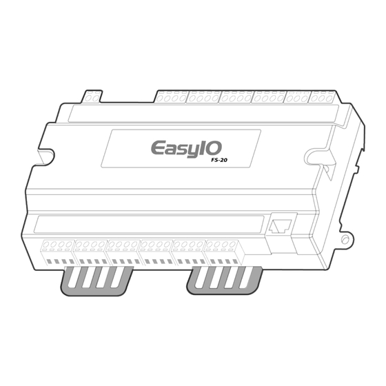
Figure 1: FS-20 front view
Figure 2: FS-20 back and side view
FS-20 Quick Start Guide
•
Connect to the controller's web server dashboard with
CPT Graphics.
Important: Use the FS-20 controller as an operating
control only. Where failure or malfunction of the
FS-20 could lead to personal injury or property
damage to the controlled equipment or other
property, design additional precautions into the
control system. Incorporate and maintain other
devices, such as supervisory or alarm systems or
safety or limit controls, intended to warn of or
protect against failure or malfunction of the FS-20.
Callout
Description
1
DIN rail
2
Enclosure mounting holes
3
Cover screw
4
Hot and ground terminal
5
Digital output (DO) terminals
LIT-12013995
Version 1.0
2023-04-25
Advertisement
Table of Contents

Subscribe to Our Youtube Channel
Related Manuals for Johnson Controls easyIO FS-20


Summary of Contents for Johnson Controls easyIO FS-20
- Page 1 FS-20 Quick Start Guide LIT-12013995 Version 1.0 2023-04-25 Overview • Connect to the controller's web server dashboard with CPT Graphics. The FS-20 is an input/output controller with IP network Important: Use the FS-20 controller as an operating and Ethernet connectivity. Use this guide to complete the control only.
-
Page 2: Mounting Guidelines
Callout Description Callout Description Status LED Universal output (UO) and COM terminals Error LED RS-485 serial port terminals DO1 to DO2 Digital output status LED DIN rail end clips TX1 and TX2 Transmitting communication Ethernet port Universal input (UI) and COM terminals RX1 and TX2 Receiving communication LED Mounting clips... -
Page 3: Removing The Controller Cover
Mounting the controller to an enclosure base plate About this task: If a DIN rail mount is not practical, the controller features two mounting holes to screw mount the controller to an enclosure base plate. Place the controller on the enclosure surface and mark the enclosure mounting holes on the surface. - Page 4 Input, output, and 24 VAC Class Important 2 transformer power input wiring diagrams Only use copper conductors. Wire the controller in accordance with local, national, and regional regulations WARNING Risk of electric shock CAUTION Disconnect the power supply before you make electrical connections.
- Page 5 Figure 10: FS-20 wiring diagram Table 1: FS-20 wiring inputs and outputs Callout Description Power input 24 VAC or 24 VDC Pilot duty output Current-controlled VSD Voltage-controlled actuator Connection to serial devices Current transmitter 0 mA to 20 mA or 4 mA to 20 mA Voltage transmitter 0 V to 10 V or 0 V to 5 V Thermistor, RTD, or potentiometer...
- Page 6 Figure 11: 24 VAC Class 2 transformer power input Figure 13: DO wiring Callout Description 20 AWG copper stranded wire Controller H terminal Callout Description G terminal Field device 20 AWG copper stranded twisted wire up to Figure 12: Analog output wiring 100 m in length DO terminal COM terminal...
- Page 7 Figure 15: UI current mode wiring in loop Callout Description Field device 22 AWG copper stranded twisted wire up to 100 m in length Controller UI terminal COM terminal Dry contact Normally open or normally closed as required Callout Description Power supply terminal wiring Field device Connect the 24 VAC supply power wires from the...
- Page 8 Input and output terminal wiring Figure 19: RS-485 wiring considerations • Run all low-voltage wiring and cables separate from high-voltage wiring. • For all input and output cables, use twisted, insulated, and stranded copper wires. • Use shielded cables for input and output cables that are exposed to high electromagnetic or radio frequency noise.
- Page 9 Universal jumper setting Figure 20: Universal jumpers Figure 21: Current mode Callout Component Universal output jumper configuration Universal input jumper configuration Universal output jumper configuration Figure 22: Voltage mode The FS-20 controller supports current, voltage, and digital field devices. For current mode, position the jumper on the two left pins.
- Page 10 Figure 23: Digital mode Note: Use the same subnet mask and gateway as the controller. For the IP address, enter the same IP address as the controller, but change the last octet to a unique number. Use a high number that is less than 255 to avoid using an IP address that is already in use.
- Page 11 Interfacing with a controller's web d. In the IPv4 address, Subnet Mask, and Router fields, set the IP address, subnet mask, default server gateway, then click OK. About this task: From the terminal, complete the following steps: To interface with a controller's web server, complete the a.
- Page 12 What to do next: Note: By default, there is no password. To For more information about CPT, Refer to EasyIO CPT User increase security, when you log on, complete Guide (LIT-12013978). the steps outlined in Creating a new CPT admin password for a controller in EasyIO Hardening Guide (LIT-12013986).
-
Page 13: Troubleshooting
Callout Component Micro SD card slot Micro SD card Micro SD card specifications You can use a micro SD card with FS controllers for extra backup storage. Use a micro SD card that meets the following specifications: Table 4: Micro SD card specifications Specification Remark Recommended tested brands... -
Page 14: Technical Specifications
Table 5: FS troubleshooting Problem Cause Solution Analog mode for a The COM terminal is not connected. Connect the COM terminal of the configurable output to configurable output is the common of the connected end device. invalid. For example, 0 V Measure the output and verify that it matches the to 10 V output results in command. -
Page 15: Product Warranty
LANE GLENDALE, WI NO. 32 53209 NETHERLANDS MANCHESTER CHANGJIANG M40 2WL RD NEW UNITED DISTRICT KINGDOM WUXI JIANGSU PROVINCE 214028 CHINA Contact information Contact your local Johnson Controls representative: www.johnsoncontrols.com/locations Contact Johnson Controls: www.johnsoncontrols.com/ contact-us FS-20 Quick Start Guide... - Page 16 © 2023 Johnson Controls. All rights reserved. All specifications and other information shown were current as of document revision and are subject to change without notice. www.johnsoncontrols.com...
Need help?
Do you have a question about the easyIO FS-20 and is the answer not in the manual?
Questions and answers