Table of Contents
Advertisement
Application
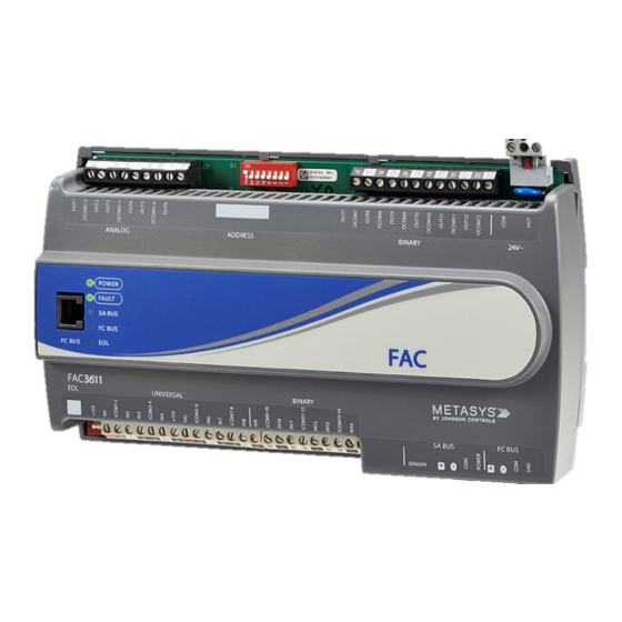
The FAC3611 Advanced Application Field Equipment
Controller (FAC) is part of the Metasys
Equipment Controller family. The FAC36 Series controllers
run pre-engineered and user-programmed applications
and provides the inputs and outputs required to monitor
and control a wide variety of HVAC and other facility
equipment.
FAC36 controllers operate on an RS-485 BACnet
Bus as BACnet Advanced Application Controllers (B-AACs)
and integrate into Johnson Controls
BACnet systems.
FAC36 field controllers include an integral real-time
clock, which enables the controllers to monitor and
control schedules, calendars, and trends, and operate for
extended periods of time as stand-alone controllers when
offline from the Metasys system network.
Switchable communications protocols
By default, the Metasys system FEC Family Controllers
and network sensors communicate using the standard
BACnet protocol based on the ANSI/ASHRAE 135-2008. The
BACnet protocol is a standard for ANSI, ASHRAE, and the
International Standards Organization (ISO) for building
controls.
FEC, VMA16, and VMA18 are BTL-listed as BACnet
Application Specific Controllers (B-ASCs). FAC Field
Controllers and the VMA1930 Field Controller are BTL-
listed as BACnet Advanced Application Controllers (B-
AACs). The NS Series Sensors are BTL-listed as BACnet
Smart Sensors (B-SSs).
Release 10.1 and later of the Controller Configuration Tool
(CCT) can be used to switch the Field Bus communications
protocol in supported FEC Family Field Controllers to be
either the standard BACnet MS/TP or the N2 protocol.
All new controllers use BACnet MS/TP as the default
communications protocol. Switchable communications
protocols in the MS/TP models provide a cost-effective
upgrade and modernization path for customers with
existing N2 controllers.
The N2-capable FEC Family Controllers can be used as
functional replacements for legacy N2 controllers. The N2-
capable FEC Family Controllers:
• have the input and output (I/O) quantities and
characteristics of the FEC Family Controllers
• must be programmed with CCT
• support SA Bus devices
• support WRZ wireless sensors from the controller using
the WRZ-7860 receiver (most models)
• are available in Buy American versions (most models)
FAC3611 Advanced Application Controller
system Field
®
MS/TP
®
and third-party
®
Installation Guide
The N2-capable controllers:
• do not support Zone Bus (for example, TMZ sensors
and M100 actuators) or XT-Bus (System 91) devices (for
example, XT, XTM, and XP modules)
• do not support a wireless connection to the N2 bus
• do not support NxE passthrough
Fast persistence
The FAC3611 model has been significantly upgraded and
now includes a fast persistence feature that allows you to
retain data values at a configurable interval, up to once
per second. Persistence refers to how often samples of
data are stored locally. This upgrade to the persistence
feature ensures that in the event of a problem, such as a
loss of power, more recent data can be retrieved up to the
rate that the data is persisted, minimizing the potential
loss of data. When power is restored, previously persisted
data, up to the rate of persistence, is still available and
accessible. When persistence is configured for once per
second, you risk losing only the most recent one second
of data before the power loss. Persisting data may be
essential for situations that require greater data accuracy.
This may include certain methods of utility data collection
and billing
Attributes that can be persisted in the FAC3611 include:
Counter Input Present Value Attributes, Binary Input,
Binary Output, and Binary Value COS Counts and Active
Time Attributes, and PID/PRAC tuning parameters.
North American emissions compliance
United States
This equipment has been tested and found to comply with
the limits for a Class A digital device pursuant to Part 15
of the FCC Rules. These limits are designed to provide
reasonable protection against harmful interference when
this equipment is operated in a commercial environment.
This equipment generates, uses, and can radiate radio
frequency energy and, if not installed and used in
accordance with the instruction manual, may cause
harmful interference to radio communications. Operation
of this equipment in a residential area may cause harmful
interference, in which case the users will be required to
correct the interference at their own expense.
Canada
This Class (A) digital apparatus meets all the requirements
of the Canadian Interference-Causing Equipment
Regulations.
Cet appareil numérique de la Classe (A) respecte toutes
les exigences du Règlement sur le matériel brouilleur du
Canada.
Part No. 24-10143-470 Rev. G
2019-10-18
*2410143470G*
(barcode for factory use only)
MS-FAC3611
Advertisement
Table of Contents

Subscribe to Our Youtube Channel
Related Manuals for Johnson Controls FAC3611


Summary of Contents for Johnson Controls FAC3611
- Page 1 BACnet protocol is a standard for ANSI, ASHRAE, and the and billing International Standards Organization (ISO) for building Attributes that can be persisted in the FAC3611 include: controls. Counter Input Present Value Attributes, Binary Input, FEC, VMA16, and VMA18 are BTL-listed as BACnet Binary Output, and Binary Value COS Counts and Active Application Specific Controllers (B-ASCs).
-
Page 2: Installation
Binary Input (BI) Terminal Block: Dry Contact Maintained controller, DIN rail, and any user-supplied enclosure. or Pulse Counter/Accumulator Mode (see Terminal wiring • Mount the controller horizontally on 35 mm DIN rail guidelines, functions, ratings, and requirements whenever possible. FAC3611 Advanced Application Controller Installation Guide... -
Page 3: Wall Mount Applications
Securely mount a 23 cm (9.125 in.) or longer section of 35 mm DIN rail, horizontally and centered in the desired space. Pull the two bottom mounting clips outward from the controller to the extended position (Figure 3). FAC3611 Advanced Application Controller Installation Guide... - Page 4 Wiring Terminal blocks and bus ports FAC3611 physical features for terminal block and bus port locations on the FAC3611 controller. Observe the CAUTION following guidelines when wiring a controller. Input and Output terminal blocks Risk of Electric Shock: The fixed input terminal blocks are located on the bottom...
-
Page 5: Supply Power Terminal Block
Powering network devices with uniform 24 VAC supply power phasing reduces noise, interference, and ground loop problems. The field controller does not require an earth ground connection. FAC3611 Advanced Application Controller Installation Guide... -
Page 6: I/O Terminal Blocks, Ratings, And Requirements
Note: All Universal ICOMn terminals share a ICOMn Same as (Universal) INn common, which is isolated from all other commons, except the SA bus common. One common screw terminal point is provided for every two input screw terminal points. FAC3611 Advanced Application Controller Installation Guide... -
Page 7: Cable And Wire Length Guidelines
The following table defines cable length guidelines for the regional electrical codes. various wire sizes that may be used for wiring low-voltage (<30 V) input and outputs. FAC3611 Advanced Application Controller Installation Guide... -
Page 8: Maximum Cable Length Versus Load Current
Recommended cable type Port label FC Bus Communications 0.6 mm (22 AWG) stranded, 3-wire Signal Reference (Common) for Bus FC BUS twisted, shielded cable recommended communications Isolated terminal (optional shield drain SHLD connection ) FAC3611 Advanced Application Controller Installation Guide... - Page 9 24 VAC Power Supply - Hot Supply 20–30 VAC (Nominal 24 VAC) 0.8 mm to 1.0 mm 24 VAC Power Supply Common (Isolated from (18 AWG) 2-wire all other Common terminals on controller) 14 VA FAC3611 Advanced Application Controller Installation Guide...
-
Page 10: Termination Diagrams
Termination diagrams See the figures in this section for the applicable termination diagrams. A set of Johnson Controls termination diagrams provides details for wiring inputs and outputs to the controllers. Table 5: Termination details Type of field Type of Input/... - Page 11 Termination diagrams device Output Current Input - External Source (Isolated) Current Input - Internal Source (2- wire) Current Input - Internal Source (3 wire) Current Input - External Source (in Loop) Feedback from EPP-1000 FAC3611 Advanced Application Controller Installation Guide...
- Page 12 0–10 VDC Output to Actuator CO or AO (External Source) 0–10 VDC Output to Actuator CO or AO (Internal Source) Current Output CO or AO 24 VAC Triac Output (Switch CO or AO Low, External Source) FAC3611 Advanced Application Controller Installation Guide...
- Page 13 Type of Input/ Termination diagrams device Output Analog Output (Current) 4–20 mA Output to Actuator 4–20 mA Output to Actuator Incremental Control to Actuator (Switch Low, Externally Sourced) 24 VAC Binary Output (Switch Low, Externally Sourced) FAC3611 Advanced Application Controller Installation Guide...
- Page 14 SA Bus Address = 199) Note: The bottom jack (J2) on the TE-700 and TE-6x00 Series Sensors is not usable as a zone bus or an SAB connection. Network Stat with Terminals SA Bus Addressable FAC3611 Advanced Application Controller Installation Guide...
-
Page 15: Setup And Adjustments
DIP switch block on the expansion module's cover. The following table describes the FC bus and SA bus device addresses for Johnson Controls MS/TP communica- tions bus applications. Table 6: SA/FC bus device address descriptions... -
Page 16: Setting The N2 Controller Address To Be Greater Than 127
Setting the End-of-Line (EOL) switch Each field controller has an EOL switch, which, when set to ON, sets the controller as a terminating device on the bus. The default EOL switch position is OFF. FAC3611 Advanced Application Controller Installation Guide... -
Page 17: Ui Current Loop Jumpers
The following table identifies the current loop switches associated with each UI on the controller. Setting the Input Jumpers Table 7: FAC3611 UI Inputs and jumper labels CAUTION Universal Input label Jumper label on circuit board Risk of Electric Shock:... -
Page 18: Troubleshooting Controllers
On Steady = EOL switch in ON position Amber terminating Off Steady = EOL switch in Off position devices) Repair information If controller fails to operate within its specifications, replace the controller. For a replacement controller, contact your Johnson Controls representative. FAC3611 Advanced Application Controller Installation Guide... -
Page 19: Accessories Ordering Information
Wireless Field Bus System Product Bulletin (LIT-12012320) for a list of available products. WRZ Series Wireless Refer to the WRZ Series Wireless Room Sensors Product Bulletin (LIT-12000653) for specific sensor model Room Sensors descriptions. FAC3611 Advanced Application Controller Installation Guide... -
Page 20: Technical Specifications
Canada: UL Listed, File E107041, CCN PAZX7 CAN/CSA C22.2 No.205, Signal Equipment Industry Canada Compliant, ICES-003 Europe: Johnson Controls, Inc. declares that this product is in compliance with the essential requirements and other relevant provisions of the EMC Directive. Australia and New Zealand: RCM Mark, Australia/NZ Emissions Compliant BACnet International: BACnet Testing Laboratories™... -
Page 21: Product Warranty
The performance specifications are nominal and conform to acceptable industry standard. For application at conditions beyond these specifications, consult the local Johnson Controls office. Johnson Controls shall not be liable for damages resulting from misapplication or misuse of its products. - Page 22 FAC3611 Advanced Application Controller Installation Guide...
Need help?
Do you have a question about the FAC3611 and is the answer not in the manual?
Questions and answers