Table of Contents
Advertisement
Quick Links
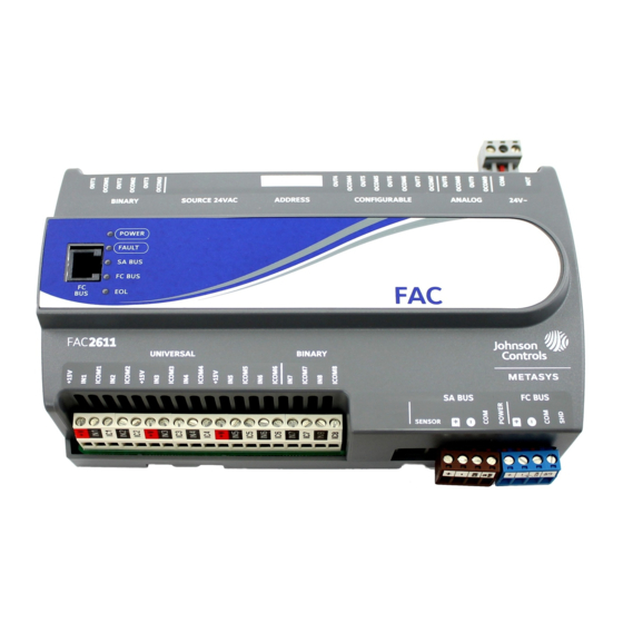
FAC2611-0U Advanced Application Field Equipment
Controller Installation Instructions
MS-FAC2611-0U
Application
The FAC2611 Advanced Application Field Equipment
Controller (FAC) is part of the Metasys® system Field
Equipment Controller family. The FAC26 Series
controllers run pre-engineered and user-programmed
applications and provide the inputs and outputs required
to monitor and control a wide variety of HVAC equipment.
FAC26 field controllers operate on an RS-485 BACnet®
MS/TP Bus as BACnet Advanced Application Controllers
(B-AACs) and integrate into Johnson Controls® and
third-party BACnet systems.
FAC26 controllers include an integral real-time clock,
which enables the controllers to monitor and control
schedules, calendars, and trends; and operate for
extended periods of time as stand-alone controllers when
offline from the system network.
Important: The MS-FAC2611-0U model is used in
Metasys Release 8.1 smoke control
applications and is UL 864 UUKL/UUKLC
10th Edition Smoke Control Listed. You
must refer to the Metasys® System UL 864
10th Edition UUKL/ORD-C100-13 UUKLC
Smoke Control System Technical Bulletin
(LIT-12012487) for detailed requirements
and procedures for installing,
commissioning, and operating UL 864
UUKL/UUKLC Listed Metasys system
devices. The UL 864 UUKL/UUKLC listing
for Smoke Control Equipment is voided if
(1) you do not use the required software
tools at the required versions; or (2) you do
not meet the requirements or do not follow
the procedures as documented in the
Metasys® System UL 864 10th Edition
UUKL/ORD-C100-13 UUKLC Smoke
Control System Technical Bulletin
(LIT-12012487).
FAC2611-0U Advanced Application Field Equipment Controller Installation Instructions
Part No. 24-10143-01620, Rev. —
Switchable Communications
Protocols
The Family Controllers and network sensors communicate
using the standard BACnet protocol, based on the
ANSI/ASHRAE 135-2004. The BACnet protocol is a
standard for ANSI, ASHRAE, and the International
Standards Organization (ISO) for building controls.
Most FEC, VMA16, VMA18,IOM field controllers are
BTL-listed as BACnet Application Specific Controllers
(B-ASCs). FAC field controllers and the VMA1930 Field
Controller are BTL-listed as BACnet Advanced Application
Controllers (B-AACs).
You can use Release 10.3 and Release Module (RM)
10.2 of the Controller Configuration Tool (CCT) to switch
the Field Bus communications protocol in supported FEC,
FAC and VMA controllers to be either the standard
BACnet MSTP or the N2 protocol. All new controllers use
BACnet MSTP as the default communications protocol.
Switchable communications protocols in the MSTP
models provide a cost-effective upgrade and
modernization path for customers with existing N2
controllers.
The N2-capable FEC Family Controllers can be used as
functional replacements for legacy N2 controllers. The
N2-capable FEC Family Controllers:
•
have the input and output (I/O) quantities and
characteristics of the FEC Family Controllers
•
must be programmed with CCT, which has similar,
but not identical programming capabilities as
HVACPro, GX9100, GPL, and other legacy tools
•
support SA Bus devices
•
are available in Buy American versions (most models)
•
are listed for UL864 UUKL/UUKLC (some models).
N2 is supported as part of the Metasys® 10th Edition
listing for Smoke Control System Equipment.
Software Release 8.1
Issued March 2018
1
Advertisement
Table of Contents

Related Manuals for Johnson Controls FAC2611-0U


Summary of Contents for Johnson Controls FAC2611-0U
- Page 1 UUKL/ORD-C100-13 UUKLC Smoke • are listed for UL864 UUKL/UUKLC (some models). Control System Technical Bulletin N2 is supported as part of the Metasys® 10th Edition (LIT-12012487). listing for Smoke Control System Equipment. FAC2611-0U Advanced Application Field Equipment Controller Installation Instructions...
-
Page 2: North American Emissions Compliance
• one field controller with removable terminal blocks • Do not install the controller in an airtight enclosure. (Power, SA, and FC bus are removable) • one installation instructions sheet FAC2611-0U Advanced Application Field Equipment Controller Installation Instructions... -
Page 3: Din Rail Mount Applications
DIN rail. To remove the controller from the DIN rail, pull the bottom mounting clips out to the extended position and carefully lift the controller off the DIN rail. FAC2611-0U Advanced Application Field Equipment Controller Installation Instructions... - Page 4 End-of-Line (EOL) Switch, located under the cover. (see Setting the End-of-Line (EOL) Switch) LED Status Indicators (see Table FC Bus Port (RJ-12 6-pin Modular Jack) (see FC Bus Port) Binary Outputs (BO) Terminal Block: 24 VAC Triac (see Table FAC2611-0U Advanced Application Field Equipment Controller Installation Instructions...
-
Page 5: Input And Output Terminal Blocks
FAC Terminal Blocks and Bus Ports Terminal Block Rating and Requirements Table for more information. Figure 3 for terminal block and bus port locations on the FAC2611 controller. Observe the following guidelines when wiring a controller. FAC2611-0U Advanced Application Field Equipment Controller Installation Instructions... -
Page 6: Sensor Port
Powering network devices with uniform 24 VAC supply power phasing reduces noise, interference, and ground loop problems. The field controller does not require an earth ground connection. FAC2611-0U Advanced Application Field Equipment Controller Installation Instructions... -
Page 7: Wireless Network Applications
UUKL/UUKLC Listed Metasys system devices. Termination Details A set of Johnson Controls® termination diagrams provides details for wiring inputs and outputs to the controllers. See the figures in this section for the applicable termination diagrams. Table 2: Termination Details Type of Field... - Page 8 Termination Diagrams Device Input/Output Voltage Input (Self-Powered) Current Input - External Source (Isolated) Current Input - Internal Source (2-wire) Current Input - Internal Source (3 wire) Current Input - External Source (in Loop) FAC2611-0U Advanced Application Field Equipment Controller Installation Instructions...
- Page 9 Type of Termination Diagrams Device Input/Output Feedback from EPP-1000 Dry Contact UI or BI (Binary Input) 0–10 VDC Output to Actuator (External Source) 0–10 VDC Output to Actuator (Internal Source) Current Output FAC2611-0U Advanced Application Field Equipment Controller Installation Instructions...
- Page 10 Table 2: Termination Details Type of Field Type of Termination Diagrams Device Input/Output 24 VAC Triac Output (Switch Low, External Source) Analog Output (Current) 4–20 mA Output to Actuator 4–20 mA Output to Actuator FAC2611-0U Advanced Application Field Equipment Controller Installation Instructions...
- Page 11 Output (Switch Low, Externally Sourced) (Triac Jumpers Where Applicable) 24 VAC Binary Output (Switch High, Externally Sourced) (Triac Jumpers Where Applicable) Incremental Control to Actuator (Switch High, Externally Sourced) (Triac Jumpers Where Applicable) FAC2611-0U Advanced Application Field Equipment Controller Installation Instructions...
- Page 12 Note: The bottom jack (J2) on the TE-700 and TE-6x00 Series Sensors is not usable as a zone bus or an SAB connection. Network Stat with SA Bus Terminals Addressable Network Stat with SA Bus Terminals (Fixed Address = 199) FAC2611-0U Advanced Application Field Equipment Controller Installation Instructions...
-
Page 13: Terminal Wiring Guidelines, Functions, Ratings, And Requirements
Internal 12 V. 15k ohm pull up ICOMn Universal Input Common for all Universal Input terminals Same as (Universal) INn Note: All Universal ICOMn terminals share a common, which is isolated from all other commons. FAC2611-0U Advanced Application Field Equipment Controller Installation Instructions... - Page 14 300 may not operate as intended for Current Mode applications. OCOMn Analog Output Signal Common for all Analog OUT terminals. Note: All Analog Output Common terminals (OCOMn) share a common, which is isolated from all other commons. FAC2611-0U Advanced Application Field Equipment Controller Installation Instructions...
- Page 15 Internal (INT) power. Internal Power Source: 30 VAC maximum output voltage 0.5 A maximum output current 1.3 A at 25% duty cycle Maximum 6 cycles/hour with M9220BGx-3 40 mA minimum load current FAC2611-0U Advanced Application Field Equipment Controller Installation Instructions...
- Page 16 Binary Input common. Binary Output Signal Common All Configurable Outputs (COs) defined as Binary Outputs are isolated from all other commons, including other CO commons. FAC2611-0U Advanced Application Field Equipment Controller Installation Instructions...
-
Page 17: Cable And Wire Length Guidelines
Note: Figure 8 applies to low-voltage (<30 V) inputs and outputs only. Figure 8: Maximum Wire Length for Low-Voltage (<30 V) Inputs and Outputs by Current and Wire Size FAC2611-0U Advanced Application Field Equipment Controller Installation Instructions... -
Page 18: Sa/Fc Bus And Supply Power Wiring Guidelines
24 AWG 3-pair CAT3 cable <30.5 Sensor m (100 ft) SA Bus Communications SA Bus Signal Reference and 15 VDC Common 15 VDC Power for devices on the SA bus and Bluetooth Commissioning Converter FAC2611-0U Advanced Application Field Equipment Controller Installation Instructions... -
Page 19: Setup And Adjustments
Table 6 describes the FC bus and SA bus devices To set the device addresses on Metasys® field addresses for Johnson Controls® MS/TP controllers: communications bus applications. FAC2611-0U Advanced Application Field Equipment Controller Installation Instructions... -
Page 20: Setting The N2 Controller Address To Be Greater Than 127
N2. Click OK. After the download is finished, disconnect the 24 VAC supply to the controller. Set the address switch segment labeled 128 to ON. FAC2611-0U Advanced Application Field Equipment Controller Installation Instructions... -
Page 21: Setting The End-Of-Line (Eol) Switch
Mise En Garde: Risque de décharge électrique Débrancher l'alimentation de l'controller avant tout réglage du Binary Output Source Power Selection Jumpers. Le non-respect de cette précaution risque de provoquer une décharge électrique. FAC2611-0U Advanced Application Field Equipment Controller Installation Instructions... -
Page 22: Ui Current Loop Jumpers
UI terminals, which maintains the 4-20 mA current the Controller Configuration Tool (CCT) software. Refer loop circuit even when power to the controller is to Controller Tool Help (LIT-12011147) for detailed interrupted or off. information on commissioning field controllers. FAC2611-0U Advanced Application Field Equipment Controller Installation Instructions... -
Page 23: Troubleshooting Field Controllers
Control Technical Specifications Table 10: FAC2611-0U Field Application Controller Product Code Numbers MS-FAC2611-0U Field Application Controller, UL/cUL 864 Listed for Smoke Control Supply Voltage 24 VAC (nominal, 20 VAC minimum/30 VAC maximum), 50/60 Hz, power supply Class 2 (North America) - Page 24 Note: Mounting space requires an additional 50 mm (2 in.) space on top, bottom and front face of controller for easy cover removal, ventilation and wire terminations. Weight 0.5 kg (1.1 lb) FAC2611-0U Advanced Application Field Equipment Controller Installation Instructions...
- Page 25 The performance specifications are nominal and conform to acceptable industry standard. For application at conditions beyond these specifications, consult the local Johnson Controls® office. Johnson Controls shall not be liable for damages resulting from misapplication or misuse of its products.
Need help?
Do you have a question about the FAC2611-0U and is the answer not in the manual?
Questions and answers