Table of Contents
Advertisement
Quick Links
Applications
FX-PCV1826 controllers are well-suited for commercial zoning applications and can be used
for pressure dependent VAV box applications where no differential pressure tranduser (DPT) is
required.
Note: At Controller Configuration Tool (CCT) 13.0 or later, using Release Mode 10.1, the PCV18
Series controllers can be configured as either N2 devices or as standard BACnet
devices. This ability provides a potential cost-effective protocol upgrade path for existing
customers and should be considered when you install the controller.
Important: When you receive an FX-PCV18 Series controller from the factory or upgrade the
firmware or main code, the controller defaults to using the MS/TP communications protocol.
The Load Summary screen of CCT shows the connection as Wired Field Bus, indicating that
the MS/TP protocol is in use. If you have an N2 application, the Load Summary screen indicates
that you need to switch the communications protocol to N2.
These FX-PCV controllers feature an integral digital pressure sensor (FX-PCV1832 model only), a
damper actuator, and a 32-bit microprocessor. The controller's small package size facilitates quick
field installation and efficient use of space for field replacements, while still enabling precision
control performance.
Note: Connecting an FX-PCX to the FX-PCV via the SA Bus connection is not supported.
North American Emissions Compliance
United States
This equipment has been tested and found to comply with the limits for a Class A digital device
pursuant to Part 15 of the FCC Rules. These limits are designed to provide reasonable protection
against harmful interference when this equipment is operated in a commercial environment.
This equipment generates, uses, and can radiate radio frequency energy and, if not installed
and used in accordance with the instruction manual, may cause harmful interference to
radio communications. Operation of this equipment in a residential area may cause harmful
interference, in which case the users will be required to correct the interference at their own
expense.
Canada
This Class (A) digital apparatus meets all the requirements of the Canadian Interference-Causing
Equipment Regulations.
Cet appareil numérique de la Classe (A) respecte toutes les exigences du Règlement sur le
matériel brouilleur du Canada.
Installation
Observe these guidelines when installing an FX-PCV18 Series controller:
Part No. 24-10143-381 Rev H
2019-03-22
FX-PCV1826/1832 Programmable VAV Box
Controller Installation Instructions
MS/TP
®
*2410143381H*
(barcode for factory use only)
FX-PCV1826-1, FX-PCV1832-1
Advertisement
Table of Contents

Related Manuals for Johnson Controls FX-PCV18 Series


Summary of Contents for Johnson Controls FX-PCV18 Series
- Page 1 This ability provides a potential cost-effective protocol upgrade path for existing customers and should be considered when you install the controller. Important: When you receive an FX-PCV18 Series controller from the factory or upgrade the firmware or main code, the controller defaults to using the MS/TP communications protocol.
-
Page 2: Parts Included
• Do not drop the FX-PCV controller or subject it to physical shock. Parts included • One FX-PCV18 Series controller with removable N2/FC bus terminal block • One installation instructions sheet • Two 6.35 mm x 6.35 mm (1/4 in. x 1/4 in. ) brass fittings •... - Page 3 To mount the FX-PCV18 Series controller, complete the following steps: 1. Place the FX-PCV18 Series controller in the proper mounting position on the damper shaft so that the wiring connections are easily accessible. Note: The line from the captive spacer and screw through the center of the damper shaft must be either horizontal or vertical, and the wall plate must be wall-mounted to comply with UL requirements.
- Page 4 3. Locate the damper position using the typical marking on the end of the damper shaft. See the following figure. Figure 2: Typical damper end shaft icons 4. Note the direction, clockwise (CW) or counterclockwise (CCW), required to close the damper. Grasp the damper shaft firmly with pliers, and either manually close the damper (for 90°...
-
Page 5: Wiring Diagram
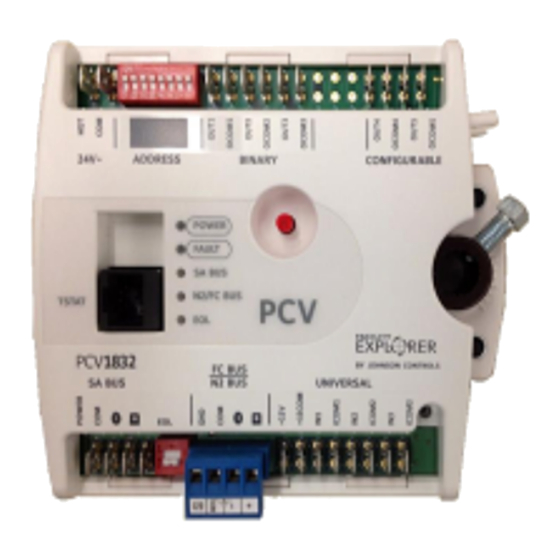
CAUTION Risk of Property Damage Rotate the damper to the full-open position before starting the air handler. Failure to rotate the damper to the full-open position may result in damage to the VAV box or ductwork when the air handler is started. - Page 6 Table 1: FX-PCV18 Series Controller feature callout numbers and descriptions Callout Physical features: description and references 24 VAC, Class 2 Supply Power Spade Terminals (see Supply power spade terminals) Device Address DIP Switch Block (see Setting the device address) Binary Outputs, 24 VAC Triacs (see Table 4) Configurable Outputs: Voltage Analog Output (0–10 VDC) and Binary Output (24 VAC...
-
Page 7: Input And Output Terminals
For detailed information on configuring and wiring an N2 Bus, refer to the N2 Communications Bus Technical Bulletin (LIT-636018). FX-PCV terminals and bus ports See Figure 3 for input and output terminal and bus port locations on the FX-PCV18 Series controllers. Observe the following guidelines when wiring an FX-PCV18 controller. Input and Output terminals The input spade terminals are located on the side of the FX-PCV near the N2/FC Bus terminal block. -
Page 8: Sa Bus Spade Lugs
SA bus spade lugs Wire the SA Bus spade lugs on the FX-PCV and other SA Bus devices in a daisy-chain configuration using 4-wire twisted, shielded cable as shown in Figure 5. See Table 6 for more information. Figure 5: SA bus spade lug wiring Note: Connecting an FX-PCX to the FX-PCV by using the SA Bus connection is not supported. - Page 9 Improper wiring of this terminal may cause a short circuit across the 24 VAC power supply on -1 models. To wire the FX-PCV18 Series controller, complete the following steps: 1. Terminate wiring per engineering drawings. 2. Wire network sensors and other devices to the FX-PCV's SA Bus.
-
Page 10: Termination Diagrams
Termination diagrams A set of Johnson Controls termination diagrams provides details for wiring inputs and outputs ® to the FX-PCV18 Series controllers. See the figures in this section for the applicable termination diagrams. FX-PCV1826/1832 Programmable VAV Box Controller Installation Instructions... - Page 11 Table 2: Termination details Type of field Type of Termination diagrams device Input/ Output Voltage Input - External Source Voltage Input - Internal Source Voltage Input (Self-Powered) Temperature Sensor Dry Contact 0–10 VDC Output to Actuator (External Source) FX-PCV1826/1832 Programmable VAV Box Controller Installation Instructions...
- Page 12 Table 2: Termination details Type of field Type of Termination diagrams device Input/ Output 0–10 VDC Output to Actuator (Internal Source) 24 VAC Triac Output (Switch Low, External Source) Note: Only applies to CO4 and CO5. Incremental Control to Actuator (Switch Low, External Source) Note: Applies to CO4 and CO5.
- Page 13 Table 2: Termination details Type of field Type of Termination diagrams device Input/ Output Temperature SA Bus Sensor with Modular Jack Note: The bottom jack (J2) on the TE-700 and TE-6x00 Series Sensors are not usable as a zone bus or an SAB connection. Network Stat SA Bus with Terminals...
-
Page 14: Sensor Replacement And Reuse Scenarios
Figure 8: FX-PCV replacement wiring diagram Sensor replacement and reuse scenarios This section describes sensor replacement and reuse scenarios for replacing a PCV1410, PCV1415, PCV1420, or the PCV controller with FX-PCV18 controllers. See Table 3 for a description of the most popular sensor models used with the PCV1410, PCV1415, PCV1420, and the PCV controllers, the sensor replacement and reuse scenarios for that sensor model, and sensor replacement and reuse instructions. -
Page 15: Sensor Replacement And Reuse Scenarios Table
Sensor replacement and reuse scenarios table Table 3: Sensor replacement and reuse scenarios Sensor used with PCV1410, Sensor replacement and Instructions PCV1415, PCV1420, PCV1440 reuse scenarios Controller TE-6xxx Series (see TE-6xxx Replace a sensor with an NS Replacing a TE-6xxx series series sensor connected to FX- Series Sensor sensor... -
Page 16: Replacing A Te-6Xxx Series Sensor
Note: If temporary occupancy is required for the application on the TE-67xx and TE-68xx Series Sensors, set the DIP switch positions on the back of the sensor to down, up, and down. This setting only applies to single and no setpoint controller models (not dual setpoint controller models). -
Page 17: Reusing A Te-6Xxx Series Sensor
Reusing a TE-6xxx series sensor To reuse a TE-6xxx Series Sensor with the FX-PCV controller, complete the instructions in this section. The Y adapter provided in the FX-PCV18 accessory pack is required for this procedure. Note: The adapter must be installed at the FX-PCV controller location. To install the adapter at the FX-PCV controller location, see Installing the adapter at the FX-PCV Controller... - Page 18 3. Plug the 6-pin male jack on the single socket adapter into the modular jack connection on the back of the NS Series Network Sensor. 4. Mount the NS Series Network Sensor in the same location the AP-TMZ1600-0 Sensor was previously mounted, concealing the adapter assembly in the existing wall opening behind the sensor.
-
Page 19: Input And Output Wiring Guidelines Tables
Replacing a TE-700 Series sensor Replace a TE-700 Series Sensor with a TE-730 Series Sensor. No cable adapters are required for this scenario. Note: Refer to the TE-730 Series Sensor Installation Instructions (Part No. 24-10674-0) to install the TE-730 Series Sensor. Reusing a TE-700 Series sensor See the instructions in this section to reuse a TE-700 Series Sensor when connected to an FX-PCV18 controller. - Page 20 Analog Input - Resistive Mode (0– See Guideline A in Table 600k ohm) Internal 12 V, 15k ohm pull up Qualified Sensors: 0–2k potentiometer, RTD (1k Nickel [ Johnson Controls sensor], 1k Platinum, and A99B Silicon Temperature Sensor) Negative Temperature Coefficient (NTC) Sensor 10K Type L (10K JCI Type II is equivalent to Type L) or 2.252K Type...
- Page 21 Table 4: I/O terminal blocks, functions, ratings, requirements, and cables Terminal block Terminal Function, ratings, and To determine wire size label labels requirements and maximum cable length OCOMn Binary Output - 24 VAC Triac See Guideline C in Table (Internal Power) Connects OCOMn to 24~ COM when activated.
- Page 22 Table 5: Cable length guidelines for recommended wire sizes Guideline Wire size/Gauge and type Maximum cable length Assumptions and type 1.0 mm² (18 AWG) stranded 457 m (1,500 ft) twisted 100 mV maximum copper wire voltage drop 0.8 mm (20 AWG) stranded 297 m (975 ft) twisted Depending on the copper 297 m (975 ft) twisted...
-
Page 23: Communication Bus And Supply Power Table
Communication bus and supply power table Table 6: Communication bus and supply power terminal blocks, functions, ratings, requirements, and cables Terminal block/ Terminal labels Function, electrical Recommended cable type Port label ratings/Requirements N2/FC Bus Use existing cable or 18 N2/FC BUS Communications Signal Reference (Common) for bus communications... -
Page 24: Setup And Adjustments
Setup and adjustments Important: Electrostatic discharge can damage controller components. Use proper electrostatic discharge precautions during installation, setup, and servicing to avoid damaging the controller. Setting the device address FX-PCV18 controllers are subordinate devices on N2 buses. Before operating field controllers on a bus, you must set a valid and unique device address for each controller on the bus. -
Page 25: Setting The Eol Switch
Setting the EOL switch Each field controller has an EOL (End of Line) switch, which, when set to ON (up), sets the field controller as a terminating device on the bus. See Figure 3 for the EOL switch location on the field controller. -
Page 26: Troubleshooting
24 VAC power supply on -1 models. Repair information If the FX-PCV18 Series controller fails to operate within its specifications, replace the unit. For a replacement unit, contact the nearest Johnson Controls representative. -
Page 27: Technical Specifications
Table 8: FX-PCV18 Controller accessories. Order separately Product Code Number Description Mobile Access portal To identify the appropriate product for your region, refer to the Mobile (MAP) Gateway Access Portal Gateway Catalog Page (LIT-1900869). NS Series Network Refer to the NS Series Network Sensors Product Bulletin (LIT-12011574) for Sensors specific sensor model descriptions. - Page 28 Table 9: FX-PCV18 Controllers Ambient Conditions Operating: 0°C to 50°C (32°F to 122°F) Storage: -40°C to 70°C (-40°F to 158°F) Terminations Inputs/Outputs, SA bus, and Supply Power: 6.3 mm (1/4 in.) Spade Lugs N2/FC Bus Pluggable Screw Terminal Block TSTAT Modular Port: RJ-45 8-Pin Modular Jack Controller Addressing N2 Open Protocol: Valid field controller device addresses 1–253 BACnet MS/TP: DIP switch set;...
-
Page 29: Points Of Single Contact
The performance specifications are nominal and conform to acceptable industry standard. For application at conditions beyond these specifications, consult the local Johnson Controls office. Johnson Controls shall not be liable for damages resulting from misapplication or misuse of its products. - Page 30 © 2019 Johnson Controls. All rights reserved. All specifications and other information shown were current as of document revision and are subject to change without notice. www.johnsoncontrols.com...
Need help?
Do you have a question about the FX-PCV18 Series and is the answer not in the manual?
Questions and answers