Table of Contents
Advertisement
Quick Links
S
HOWER
IMPORTANT
DreamLine
reserves the right to alter, modify or redesign products at any time without prior notice for the
®
purpose of product improvement and customer experience. Please refer to the model's web page on
DreamLine.com for the latest technical drawings, installation manuals, warranty information or additional
product details.
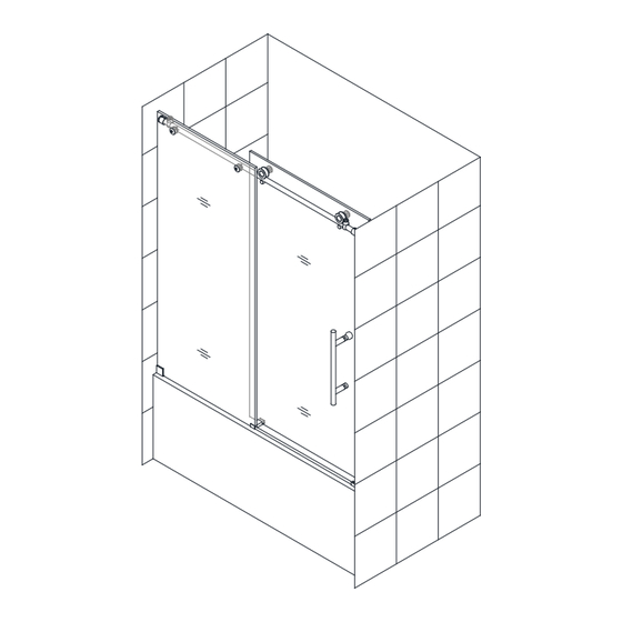
SHDR-61606210-##
Right-hand door installation shown
PLEASE REVIEW THIS ENTIRE MANUAL PRIOR TO INSTALLATION
For more information about DreamLine
ENIGMA-X shower and tub door manual Ver 6 Rev 7 07/2018
ENIGMA-X
D
I
OOR
NSTALLATION
SHDR-61487610-##
SHDR-61607610-##
Shower Doors & Tub Doors please visit DreamLine.com
®
I
NSTRUCTIONS
SHDR-61727610-##
##=finish
07- Brushed Stainless Steel
08- Polished Stainless Steel
18- Tuxedo
©2018 DreamLine. All Rights Reserved
Advertisement
Table of Contents

Subscribe to Our Youtube Channel
Related Manuals for Dreamline ENIGMA-X SHDR-61606210 Series


Summary of Contents for Dreamline ENIGMA-X SHDR-61606210 Series
- Page 1 ® purpose of product improvement and customer experience. Please refer to the model’s web page on DreamLine.com for the latest technical drawings, installation manuals, warranty information or additional product details. SHDR-61606210-##...
- Page 2 This model is treated with DreamLine’s exclusive ClearMax Glass technology. This is a specially formulated coating that prevents the build up of soap and water spots. Install the surface with the ClearMax label towards the inside of the shower. Please note that depending on the model, the glass may be coated on either one or both surfaces.
-
Page 3: Table Of Contents
Table of Contents Page # Section title ClearMax Coating Information Manual Selection - single threshold and enclosure return panel manual Important Model Information Reinforcement Instructions Preparation Tools Detailed Diagram ‘A’ of Shower Door Components Detailed Diagram ‘B’ of Shower Door Components Installation Steps 10-29 Guide Rail Bracket Adjustment... -
Page 4: Manual Selection - Single Threshold And Enclosure Return Panel Manual
Right-hand door installation shown 18- Tuxedo For more information about DreamLine ® Shower Doors, Tub Doors & Enclosures, please visit DreamLine.com ENIGMA-X / ENIGMA-XO Shower Enclosure Return Panel manual Ver 1 01/2018 ©2018 DreamLine. All Rights Reserved For more information about DreamLine ®... -
Page 5: Important Model Information
INSTALLATION. Roller Wheel Safety Set Screws must be retightened after installation. THE LATEST VERSION OF THE INSTALLATION Apply Thread lock. MANUAL IS AVAILABLE TO VIEW OR PRINT ON DREAMLINE.COM ENIGMA-X shower and tub door manual Ver 6 Rev 7 07/2018... -
Page 6: Reinforcement Instructions
Reinforcement for Enigma Series Heavy Glass frameless sliding shower door Install studs OR install 2”x 6” wood blocking between the studs where the Guide Rail Brackets will attach to the wall ” 2 ” S t u ” 2 ” measured from threshold* (see list below) -
Page 7: Preparation
Components”. Examine boxes and packages for shipping damage. If the unit has been damaged, has a finishing defect, or is missing parts, please contact our customer support department within 3 business days of the delivery date. Please note that DreamLine will not replace any damaged products or ®... -
Page 8: Tools
Before discarding the carton, check for small hardware bags that may have fallen to the bottom of the box. If any parts are damaged or missing, please contact DreamLine for replacement. The shipping boxes may contain extra parts not used in ®... -
Page 9: Detailed Diagram 'A'of Shower Door Components
Detailed Diagram ‘A’of Shower Door Components 9a/9b The glass surface with the ClearMax™ label must be installed to face inside of the shower for Model # SHDR-61487610-07/-08 SHDR-61607610-07/-08 SHDR-61606210-07/-08 Packing List A DESCRIPTION PART# DESCRIPTION PART# 2pcs Door stopper Guide block (with caps) Stationary glass Bumper strip ** 2pcs... -
Page 10: Detailed Diagram 'B' Of Shower Door Components
Detailed Diagram ‘B’ of Shower Door Components (for 72” model width only) for Model # SHDR-61727610-07/-08 Packing List B DESCRIPTION DESCRIPTION PART# QTY PART# 2pcs Wall anchor Ø 5/16"(8mm) Small stationary glass bracket 1set Allen Wrench 3,4,5 mm Small stationary glass Bottom bracket Anti-water strip Small stationary glass ST4.2x55 Truss Head screw... -
Page 11: Installation Steps
Installation steps Measure the distance between the two finished walls at the top, middle and bottom. Measure the width at the model height (62” or 76”). This top measurement will be the “W” dimension used to cut the guide rail to the correct size for the finished opening. - Page 12 Attach the Upper Guide Rail (#03) to the Stationary Glass (#02) panel end stopper hole with the Glass Brackets (#07) and tighten the bolts into the holes in the Upper Guide Rail (#03). Make sure both adjustment disks are installed in the same direction with the high spot towards the door end.
- Page 13 ATTENTION: This step shows the Small Stationary Glass Bracket (#21) installation for the 72” model only (not included with the 48“ or 60” model). If the model width is 72” and includes the Small Stationary Glass (#23), attach the Small Stationary Glass Bracket (#21) to the Upper Guide Rail for 72”...
- Page 14 Place the Stationary Glass (#02) with the Upper Guide Rail (#03) onto the threshold and position it against the wall. (Note that the Stationary Glass (#02) installs to the outside of the Upper Guide Rail (#03)) Make sure the Stationary Glass (#02) and the Upper Guide Rail (#03) are level. If a horizontal adjustment is required;...
- Page 15 ATTENTION: This step shows the Small Stationary Glass (#23) installation for the 72” model only (not included with the 60” model). rotate disk(s) to level rail If installing the 72” model: Unscrew the disk from the Small Stationary Glass Bracket (#21) and loosen the set screw that secures the bracket to the guide rail.
- Page 16 Once the Upper Guide Rail (#03) is level, mark the position of the Wall Bracket (#19) and Guide Rail Brackets (#08) on the wall. *NOTE: If installing the 72” model, also mark the position of the Wall Bracket (#19) on the opposite wall for the Small Stationary Panel Glass (#23) (see Fig 8.4*).
- Page 17 After marking the positions of all the hardware, set the Stationary Glass (#02) with the Upper Guide Rail (#03) aside. (If installing the 72” model, also remove the Small Stationary Panel Glass (#23) from the Upper Guide Rail (#03)). Remove the Guide Rail Brackets (#08) from the Upper Guide Rail (#03) and the Wall Bracket (#19) from the Stationary for 72”...
- Page 18 Fasten the Wall Bracket (#19) to the wall using the ST4.2×55 Truss Head Screw (#18). (Fig 12.1) If installing the 72” model, repeat this step to install the Wall Bracket (#19) for the Small Stationary Panel Glass (#23) (Fig 12.4*). Install the base parts of the Guide Rail Brackets (#08) onto both walls using the ST6×65 Large Truss Head Screw (#10).
- Page 19 13b. If installing the 72” model, repeat Step #13a for the use a pencil or a center-punch to Small Stationary Glass Bottom Bracket (#22). Loosen the mark the hole set screw and remove the Guide Block Face Plate. *NOTE: *see note ◾For installation into an Acrylic Threshold: drill an Ø1/8”(3mm) hole and use the ST4.2 x 40mm Countersunk Screw (#17)
-
Page 20: Guide Rail Bracket Adjustment
Re-position the Stationary Glass (#02) and Upper Guide Rail (#03) onto the threshold and fasten both sleeves of the Guide Rail Brackets (#08) to the brackets on the walls. Tighten the set screws on the Guide Rail Brackets (#08) to secure the Upper Guide Rail (#03). - Page 21 15a. 15b. Measure the For the 72” model size: Measure the For the 48”or 60“ model size: distance from the edge of the Guide Block (#12) distance between the edge of the Guide Block to the wall. This distance will be “X”. (#12) to the Small Stationary Glass Bottom Cut the Anti-Splash Guard (#15) to the size of: Bracket (#22).
- Page 22 Secure the Anti-Splash Guard (#15) to the threshold with several pieces of painter’s tape to hold it in position and tight to the threshold until the silicone fully cures. (Fig 17) Fig 17 Attach the Guide block face plate to the installed Guide Block (#12) and tighten the set screw with the supplied allen wrench.
- Page 23 If installing the 72” model: attach the Small Stationary Panel Glass (#23) to the Upper Guide Rail (#03) using the Small Stationary Glass Bracket (#21). Attach the face plate to the Wall Bracket (#19) on the threshold (see Fig 19.5). (Fig 19) outside Fig 19 If installing the 72”...
-
Page 24: Guide Block Installation
NOTE: DO NOT attach the handle to the door glass until instructed to do so. DO NOT attempt to lift the door glass with the handle as this may result in damage to the glass and/or serious personal injury. Attach the two Rollers (#04) to the Door Glass (#05) with the wheels facing outside of the shower. -
Page 25: Roller Guards
Attach the two Roller Guards (#29) onto the door to secure the door to the Upper Guide Rail (#03). Apply Thread Lock Adhesive (#26) to the bolts. Leave no more than a 1/16” gap between the Roller Guards (#29) and the Upper Guide Rail (#03). Tighten the bolt and screw on the cap. (Fig 22a) TIP: Position the roller guard 1/16”... -
Page 26: Vinyl Seals
Note: The Safety set screw on both wheels MUST BE re-tightened after installation to prevent the large bolt from coming loose. Apply thread lock during installation. (See details Fig 22b and also on Page 30) add threadlock to the safety set screw and wheel bolt Fig 22b 48”or 60”... -
Page 27: Door Stopper Installation
Position the Door Stoppers (#01) and screw them tightly to the Upper Guide Rail (#03). NOTE: The Door Stoppers (#01) must be positioned correctly to prevent the handle from contacting the wall Stationary Glass (#02) (48”, 60” & 72“ models) and to stop the Door Glass (#05) in a position that allows the bumper strip to create an even seal with the wall, but does not allow the door glass to bang into the wall during normal operation (48”... -
Page 28: Bumper Installation
Install the Bumper (#30) onto the threshold and against the wall on the stationary panel side of the installation. (For 72” model, this will be the side of the opening with the large stationary panel) Remove the 3M Tape and position the Bumper (#30) onto the threshold against the Wall Bracket (#19). - Page 29 To install the Bumper (#30) with the screw method, position the Bumper (#30) onto the threshold and against the wall on the stationary panel side of the installation. (For 72” model, this will be the side of the opening with the large stationary panel). and mark the position of the hole onto the wall. Drill a 5/16”...
- Page 30 Apply a good quality mildew-resistant silicone along the interior perimeter where the glass meets the wall and threshold and also along the Anti-Splash Guard (#15). (Fig 27) Allow 24 hours for the silicone to cure before using the shower. Hours Fig 27 Do Not hang or drape a towel or wash cloth over the Enigma guide rail as this may...
- Page 31 Roller adjustment procedure for: Enigma, Enigma-X, Enigma-XO To create a good seal with the wall and to achieve minimal clearance beneath the door glass without making contact with the bottom guide block or threshold. Have at least two 3/16” shims or wedge shims (to maintain space beneath the door glass) and an assistant available to help with this procedure.
-
Page 32: Product Maintenance
NOTE: To maximize the life of your door, it is important to regularly inspect the glass and other hardware for misalignment, proper attachment, and/or damage. Contact DreamLine with any questions or concerns. ®... - Page 33 TEL: 866-731-2244 FAX: 866-857-3638 DREAMLINE.COM For more information on DreamLine Shower Doors and Enclosures please visit DreamLine.com ® ©2018 DreamLine. All Rights Reserved...
Need help?
Do you have a question about the ENIGMA-X SHDR-61606210 Series and is the answer not in the manual?
Questions and answers