Advertisement
Quick Links
Shower Door Installation Instructions
IMPORTANT
DreamLine
reserves the right to alter, modify or redesign products at any time without prior notice. For the
®
latest up-to-date technical drawings, manuals or any other details please refer to your model's web page on
DreamLine.com
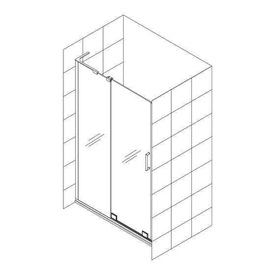
Left hand panel installation shown
Please read these instructions carefully before installing. If you have any questions regarding installation, please contact
our technical support specialists Monday through Friday 8:00 AM – 7:00 PM EST at Phone: 1-866-731-2244,
Fax: 1-866-857-3638 or e-mail our technical support group at Support@DreamLine.com
For more information about DreamLine
MIRAGE-X
Shower Doors & Tub Doors please visit DreamLine.com
®
MODEL #s
SHDR-1948723L-##
SHDR-1960723L-##
SHDR-1948723R-##
SHDR-1960723R-##
SHDR-1960580L-##
SHDR-1960580R-##
##=finish
01- Chrome
04- Brushed Nickel
Advertisement

Related Manuals for Dreamline MIRAGE-X SHDR-1948723L Series


Summary of Contents for Dreamline MIRAGE-X SHDR-1948723L Series
- Page 1 Please read these instructions carefully before installing. If you have any questions regarding installation, please contact our technical support specialists Monday through Friday 8:00 AM – 7:00 PM EST at Phone: 1-866-731-2244, Fax: 1-866-857-3638 or e-mail our technical support group at Support@DreamLine.com For more information about DreamLine Shower Doors &...
- Page 2 2. Please note that you should consult your local building codes with questions on installation compliance standards. Building and plumbing codes may vary by location, and DreamLine is not ®...
- Page 3 Before discarding the carton, check for small hardware bags that may have fallen to the bottom of the box. If any parts are damaged or missing, please contact DreamLine for replacement. The shipping boxes may contain extra parts not used in ®...
-
Page 4: Parts Diagram
Parts diagram Right hand L-Bracket Left hand L-Bracket Parts List ITEM ITEM Stopper Bottom Rail Insert Stationary Glass Bumper Seal Strip Glass Door 0.5mm Bottom Spacer Strip Bottom Guide Rail Allen Wrench 2.5mm,3mm 1 each Handle (200mm centers) Round Head screw ST4.2x30 3pcs L- Bracket (Left or Right) Wall Profile... -
Page 5: Assembly Diagram
Assembly diagram MIRAGE-X manual Ver 1 Rev 1 12/2015... -
Page 6: Installation Steps
Installation steps Measure the finished opening at the top, middle and bottom. The bottom width dimension will be “W”. Also check the threshold for level and the walls for plumb. Note that this model does not have adjustment for out-of-plumb conditions. See Fig 1 for details Fig 1 Subtract 1/16”... - Page 7 Position your Bottom Guide Rail (#03) onto the threshold and mark its position. Use a tape measure to keep it parallel with the threshold. See Fig 3 for details Mark the position of the holes on the threshold through the holes in the Bottom Guide Rail (#03) *NOTE: Use a power drill to make the holes using: ◾Ø1/8”...
- Page 8 Remove the temporary screw from the stopper hole in the Bottom Guide Rail (#03) and install the Rubber Stopper Block (#11) onto the Bottom Guide Rail (#03) on the stationary panel side using the pre-drilled Ø1/8” hole and attach using the ST4.2 x 20 screw (#08). (Left hand installation shown). Cover the screw with the supplied rubber plug.
- Page 9 Mark the Wall Profile’s (#17) position on the wall and also mark the hole locations for drilling. Remove the Wall Profile (#17) and drill Ø5/16”(6mm) holes into the wall. Insert the Wall Anchors (#06). Apply a bead of silicone to the wall or to the back of Ø5/16”...
- Page 10 Apply silicone to the inside of the Wall Profile (#17) and into the Bottom Guide Rail(#03) equal to the width of the glass. See Fig 9 for details Caulk Fig 9 Caulk Install the Stationary Glass (#01) into the Wall Profile (#17) and Bottom Guide Rail (#03) See Fig 10 for details NOTE: The Wall Profile (#17) will allow for up to 3/8”...
- Page 11 L-Bracket Assembly (#05) components Rubber pad M5 rubber tip set screw 2pcs L-Bracket Decorative cover Wall Anchor 6pcs Wall Plate ST4.2x40 6pcs M5x14 Screw 2pcs Left hand L-Bracket installation shown MIRAGE-X manual Ver 1 Rev 1 12/2015...
- Page 12 Position the L-bracket assembly (#05) onto the Stationary Glass (#01) as shown and mark the position. Remove the Wall Plate (#5.6) and mark the holes for drilling Ø3/8”(10mm) holes and insert the wall anchors. Attach the Wall Plate (#5.6) using ST4.2 x 40 (#5.7) screws.
- Page 13 Roller Assembly (#10) components / pair 10.1 Roller body (exterior) 2pcs 10.2 Rubber pad 1 4pcs 10.3 Rubber pad 2 2pcs 10.4 Bearing 2pcs Eccentric shaft 10.5 2pcs 10.6 M5x14 Allen Bolt 8pcs 10.7 Cover plate 2pcs 10.8 Decorative board 2pcs 10.9 M5x16 Allen Bolt...
- Page 14 Set the Glass Door (#02) with the attached Bottom Roller assemblies (#10) onto the Bottom Guide Rail (#03). See Fig 13 for details Fig 13 NOTE: You will need an assistant to hold the door glass in position during the next steps until the door is secured in position with the Guide Block Assembly (#09).
- Page 15 Exterior Slider Bracket (for panel) Gasket 2pcs Rubber sleeve 2pcs Shaft 2pcs Sliding pad Sliding Guide Block (for door) M5x10 set screw 2pcs M4x4 flat head screw 2pcs Fig 14 Attach the Exterior Slider Bracket (#9.1) through the notch of the installed Stationary panel glass (#01) as shown in Fig 14.1, using the Gasket (#9.2) and Rubber Sleeves (#9.3).
- Page 16 Install the Handle (#04) to the outside of the Door Glass (#02).(Fig 15.1) Attach the Bumper Seal Strip (#13) to the closing edge of the Door Glass (#02). (Fig 15.2) Apply silicone into the Bottom Guide Rail (#03) and install the Bottom Rail Insert (#12) (Fig 15.3). See Fig 15 for details door Fig 15...
- Page 17 17. Adjust the Bottom Rollers (#10) as shown. The door should operate smoothly and create a good seal with the wall. Loosen the Allen Bolt and then rotate the adjusting disk using the Roller adjustment tool (20) as shown. Hold the door glass in the desired position and re-tighten the allen bolt. See Fig 17 for details Fig 17 1/16”...
- Page 18 Attach the roller Cover Plate (#10.8), leaving approximately 1/16” of clearance beneath the bottom rail. Re-adjust if the plate makes contact with the bottom rail. See Fig 18 for details Fig 18 1/16” gap MIRAGE-X manual Ver 1 Rev 1 12/2015...
- Page 19 Remove the paper strip from the adhesive backing of the Deflector (#18) and attach all three strips to the bottom edge of the door glass as shown. Attach the Anti-water side strip (#19) to the edge of the door glass. (Notch off the inside bottom to fit around the Deflector (#18)).
- Page 20 Apply a good quality mildew-resistant silicone along the wall profile and bottom rail. Allow 24 hours for the silicone to fully cure before first use. See Fig 20 for details Fig 20 MIRAGE-X manual Ver 1 Rev 1 12/2015...
-
Page 21: Product Maintenance
Product Maintenance BASES and BACKWALLS: To ensure a long life for your acrylic back walls: wipe them off after each use with a soft cloth. To clean the acrylic back walls use non-abrasive sprays or cream based cleaners. Never use abrasive cleansers, metal brushes or scrapers that could scratch or dull the surface. - Page 22 TEL: 866-731-2244 FAX: 866-857-3638 For more information on DreamLine Shower Doors and Enclosure please visit DreamLine.com ® MIRAGE-X manual Ver 1 Rev 1 12/2015...
Need help?
Do you have a question about the MIRAGE-X SHDR-1948723L Series and is the answer not in the manual?
Questions and answers