Advertisement
Quick Links
Prism Shower Enclosure & Base
S
E
HOWER
IMPORTANT
DreamLine
reserves the right to alter, modify or redesign products at any time without prior notice.
®
For the latest up-to-date technical drawings, manuals, warranty information or additional details please refer
to your model's web page on DreamLine.com
STEP 1:
Shower Base Installation Instructions
STEP 2:
Shower Enclosure Installation Instructions
For more information about DreamLine
PRISM SHOWER ENCLOSURE & BASE
& B
NCLOSURE
Shower Doors, Tub Doors & Enclosures, please visit DreamLine.com
®
I
ASE
NSTALLATION
I
NSTRUCTIONS
©2017 DreamLine. All Rights Reserved
Advertisement

Subscribe to Our Youtube Channel
Related Manuals for Dreamline Prism DLT-1132320


Summary of Contents for Dreamline Prism DLT-1132320
- Page 1 DreamLine.com STEP 1: Shower Base Installation Instructions STEP 2: Shower Enclosure Installation Instructions For more information about DreamLine Shower Doors, Tub Doors & Enclosures, please visit DreamLine.com ® ©2017 DreamLine. All Rights Reserved PRISM SHOWER ENCLOSURE & BASE...
- Page 2 For the latest up-to-date technical drawings, manuals, warranty information or additional details please refer to your model’s web page on DreamLine.com Color options: --- - White...
-
Page 3: Important Note
“Detailed Diagram of Shower Door Components”. If the unit has been damaged, has a finishing defect, or has missing parts, please contact our customer support department within 3 business days of the delivery date. Please note that DreamLine ®... - Page 4 ©2018 DreamLine. All Rights Reserved SLIMLINE SHOWER BASE manual Ver 5 Rev 9 03/2018...
- Page 5 ©2018 DreamLine. All Rights Reserved SLIMLINE SHOWER BASE manual Ver 5 Rev 9 03/2018...
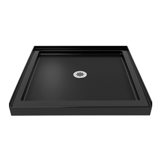
- Page 6 ©2018 DreamLine. All Rights Reserved SINGLE THRESHOLD SHOWER BASE Center Drain Configuration MODEL SPECIFICATION D (in) W (in) D1 (in) W1 (in) DLT-1132320 32"× 32" 32" 32" 15" 16" DLT-1136360 36"× 36" 36" 36" 15" 18" DLT-1132420 32” x 42”...
- Page 7 ©2018 DreamLine. All Rights Reserved SINGLE THRESHOLD SHOWER BASE Left-Hand Drain Configuration MODEL SPECIFICATION D (in) W (in) D1 (in) W1 (in) DLT-1130601 30"×60" 30" 60" 15" 12" DLT-1132601 32"×60" 32" 60" 15" 12" DLT-1134601 34"×60" 34" 60" 17" 12"...
- Page 8 ©2018 DreamLine. All Rights Reserved SINGLE THRESHOLD SHOWER BASE Right-Hand Drain Configuration MODEL SPECIFICATION D (in) W (in) D1 (in) W1 (in) DLT-1130602 30"×60" 30" 60" 15" 12" DLT-1132602 32"×60" 32" 60" 15" 12" DLT-1134602 34"×60" 34" 60" 17" 12"...
- Page 9 ©2018 DreamLine. All Rights Reserved NEO ANGLE SHOWER BASE MODEL SPECIFICATION W (in) A (in) B (in) C (in) DLT-2036360 36"×36" 36" 18 5/16" 25" 12" DLT-2038380 38"×38" 38" 20 5/16" 25" 12" DLT-2040400 40"×40" 40" 22 5/16" 25" 14 3/8"...
- Page 10 ©2018 DreamLine. All Rights Reserved QUARTER ROUND SHOWER BASE MODEL SPECIFICATION W (in) C (in) R (in) DLT-7033330 33"×33" 33" 12" 21 5/8" DLT-7036360 36"×36" 36" 12" 21 5/8" DLT-7038380 38"×38" 38" 12" 21 5/8" SLIMLINE SHOWER BASE manual Ver 5 Rev 9...
- Page 11 ©2018 DreamLine. All Rights Reserved DOUBLE THRESHOLD SHOWER BASE Corner Drain Configuration MODEL SPECIFICATION W (in) C (in) DLT-1032320 32"×32" 32" 12" DLT-1036360 36"×36" 36" 12" SLIMLINE SHOWER BASE manual Ver 5 Rev 9 03/2018...
- Page 12 ©2018 DreamLine. All Rights Reserved DOUBLE THRESHOLD SHOWER BASE Left-Hand Drain Configuration MODEL SPECIFICATION D (in) W (in) D1 (in) W1 (in) DLT-1034481 34"×48" 34" 48" 17" 12" DLT-1036481 36"×48" 36" 48" 18" 12" DLT-1036541 36"×54" 36" 54" 18" 12"...
- Page 13 ©2018 DreamLine. All Rights Reserved DOUBLE THRESHOLD SHOWER BASE Right-Hand Drain Configuration MODEL SPECIFICATION D (in) W (in) D1 (in) W1 (in) DLT-1034482 34"×48" 34" 48" 17" 12" DLT-1036482 36"×48" 36" 48" 18" 12" DLT-1036542 36"×54" 36" 54" 18" 12"...
- Page 14 ©2018 DreamLine. All Rights Reserved Shower Base Cross Section Diagram Cement board Finished Wall Shower Base (2"×4") Stud Mortar Drain* * not included SLIMLINE SHOWER BASE manual Ver 5 Rev 9 03/2018...
- Page 15 ©2018 DreamLine. All Rights Reserved Shower Base Installation - Preparation 1. Ensure that the floor and the studs are at right angles. Provide a 5”×5” opening in the sub- floor for the drain. The 2” PVC waste pipe should extend above the surface of the...
- Page 16 ©2018 DreamLine. All Rights Reserved 2. Install the shower drain (NOT INCLUDED) according to the drain installation manual (supplied with the drain). See Fig. 3 for example Fig. 3 3. Place the tray into the designated position so that the Drain cutout drops around the Drain Pipe and butt the Shower Base up against the studs.
- Page 17 ©2018 DreamLine. All Rights Reserved 4. Level the tray and place marks on the studs above the upper edge of the tile flange. See Fig. 5 for details. Level base in two directions Fig. 5 5. Mix the bedding material (Mortar, cement-sand mix, etc.) Concrete...
- Page 18 ©2018 DreamLine. All Rights Reserved 6. After the bedding material has been before poured and it sets, place the shower base into the position with the drain assembly sliding over the PVC waste pipe. It will be necessary to push...
- Page 19 ©2018 DreamLine. All Rights Reserved Fig. 9 SLIMLINE SHOWER BASE manual Ver 5 Rev 9 03/2018...
-
Page 20: Product Maintenance
To maximize the life of your door, it is important to regularly inspect the glass and other hardware for misalignment, proper attachment, and/or damage. Contact DreamLine with any questions or concerns. SLIMLINE SHOWER BASE manual Ver 5 Rev 9 03/2018... - Page 21 TEL: 866-731-2244 FAX: 866-857-3638 REAM INE.COM For more information on DreamLine ® Shower Doors Enclosures please visit DreamLine.com...
- Page 22 Please read these instructions carefully before installing. If you have any questions regarding installation, please contact our technical support specialists Monday through Friday 8:00 AM – 7:00 PM EST at Phone: 1-866-731-2244, Fax: 1-866-857-3638 or e-mail our technical support group at Support@BathAuthority.com For more information about DreamLine products please visit www.BathAuthority.com...
- Page 23 2. Please note that you should consult your local building codes with questions on installation compliance standards. Building and plumbing codes may vary by location, and DreamLine is not responsible for code compliance standards for your project and will not accept any returns.
-
Page 24: Tools Required
Tools Required Drill bit Tape Drill bit Phillips Wood Caulk Measure Pencil Screwdriver Caulk Electric Mallet Hammer Level Knife Drill “PRISM” Ver.1 Rev.3 08/2015... -
Page 25: Packing List
Before discarding the carton, check for small hardware bags that may have fallen to the bottom of the box. If any parts are damaged or missing, please contact DreamLine for replacement. The shipping boxes may contain extra parts not used in your model configuration. - Page 26 Shower Enclosure Installation 1. Draw the line on the wall according to your Shower Enclosure model size. Place the Wall profiles (02) onto the Shower base or threshold against the finished wall and level it vertically. See Fig. 1 for details. Enclosure assembly measurements:...
- Page 27 3. Apply clear silicone along the inner channel of the Glass profile (01) and push the Stationary glass (03) inside the channel. Slide the Stationary glass assembly into the groove of the Wall profile (02). NOTE: The small holes on the Stationary glass should be away from the wall.
- Page 28 5. Attach top and bottom Pivot bars (05) to the Stationary glass (03) using clear Vinyl gaskets (15), Decorative washers (18) and Hex socket bolts M8×25 (17). Place the clear Vinyl gasket between the Pivot bar and the Stationary glass to prevent glass to metal connection.
- Page 29 6. After final adjustments of both Stationary glasses (03), drill the holes, on each end, through the predrilled holes in the Wall profiles (02) into the first layer of the Glass profiles (01) using Ø 1/8” drill bit. Use the Round head screws ST4.2×10 (10) to secure the Glass profiles inside the Wall profiles.
- Page 30 7. Mount top and bottom Pivot assemblies (07) to the Pivot bars (05) using socket bolts M8×12 (16). Remove the back fastener from the Pivot assemblies. Set the Glass door (04) so the holes are aligned. Make sure the vinyl gaskets are in between the glass and the metal parts.
- Page 31 9. Apply a bead of Kitchen & Bath Waterproof silicone along interior edges Stationary glass (03), Wall profiles (02) and Pivot bar (05) to seal against the walls and threshold. See Fig. 11 for details. . 11 Product Maintenance BASES and BACKWALLS: To ensure a long life for your acrylic back walls: wipe them off after each use with a soft cloth.
- Page 32 TEL: 866-731-2244 FAX: 866-857-3638 WWW. UTHORITY.COM For more information on DreamLine Shower Enclosures please visit www.BathAuthority.com...
Need help?
Do you have a question about the Prism DLT-1132320 and is the answer not in the manual?
Questions and answers
Stunning incompetence, probably the worst manuals I’ve ever seen in my life, I hope you’ve gone out of business