Table of Contents

Subscribe to Our Youtube Channel
Related Manuals for Zapi EPS-AC0 SWs&ENC


Summary of Contents for Zapi EPS-AC0 SWs&ENC
- Page 1 ELECTRONIC • OLEODYNAMIC • INDUSTRIAL EQUIPMENTS CONSTRUCTION Via Parma, 59 – 42028 – POVIGLIO (RE) – ITALY Tel +39 0522 960050 (r.a.) – Fax +39 0522 960259 e-mail: zapi@zapispa.it – web: www.zapispa.it User Manual EPS-AC0 SWs&ENC...
- Page 2 Under no circumstances will Zapi S.p.A. be held responsible to third parties for damage caused by the improper use of the present publication and of the device/devices described in it. Zapi spa reserves the right to make changes or improvements to its products at any time and without notice.
-
Page 3: Table Of Contents
Contents INTRODUCTION ........................6 SPECIFICATION........................7 Technical specifications ..................... 7 Block diagram......................7 Electrical specifications ....................8 Mechanical specifications................... 8 2.4.1 Basic release ....................8 FUNCTIONS OF THE EPS-AC0................... 9 Manual Mode Steering ....................9 Automatic Centering ....................10 3.2.1 AUTC at key-on ..................11 3.2.2 AUTC on-demand.................. - Page 4 Config menu “SET MODEL” functions list ..........64 11.4.4 Main menu “PARAMETER CHANGE” functions list........67 11.4.5 Zapi menu “HARDWARE SETTINGS” functions list ........73 11.4.6 Zapi menu “SPECIAL ADJUSTMENT” functions list ........75 11.4.7 Main menu “TESTER” functions list ............76 Page - 4/95 AEMZP0EA - EPS-AC0 SWs&ENC - User Manual...
- Page 5 12 SPECIAL FUNCTIONS ....................... 80 12.1 Not CAN Bus assisted application................80 12.2 Acquiring the Motor resistance ................. 80 12.3 Alignment at the rest position ................... 80 12.4 Straight ahead steering numbness................81 12.5 Overshooting and Damping avoiding ............... 81 12.6 Special Debugging and Troubleshooting system .............
-
Page 6: Introduction
CAN fulfilling the norm (the redundant check of the steering command complies with the Category #3 requirement). The microprocessors combined with the ZAPI hand held controller make servicing easy and direct, reducing adjustment and troubleshooting time. Increased steering motor performance and reduced noise levels are achieved by using MOSFET technology. -
Page 7: Specification
2 SPECIFICATION 2.1 Technical specifications Steering controller for AC asynchronous 3-phase motors Digital Control using Two Microprocessors Can-Bus interface Both microprocessors Can Bus connected Encoder Interface Stepper Motor or Twin Pot Interface General Purpose Analog Input (1024 steps or 4096 steps inside a narrow window) Analog KTY84-130 thermal sensor input Two digital inputs for the toggle switches Double Safety Relay inside... -
Page 8: Electrical Specifications
2.3 Electrical specifications Battery Voltage: ................. Two part numbers: F07115 ..................24/36V 50Arms F07145 ..................36/48V 45Arms Maximum current (24/36 V): ............50 A (RMS) for 2' Maximum current (36/48 V): ............45 A (RMS) for 2' Logic Supply current: ..............max 200 mA @ 24 V Minimum Input (key) Supply Voltage after start-up:..........12 V 2.4 Mechanical specifications 2.4.1 Basic release... -
Page 9: Functions Of The Eps-Ac0
3 FUNCTIONS OF THE EPS-AC0 The eps-ac0 controls a steer system for warehouse trucks. It executes the following functions: 1) Manual mode steering 2) Automatic Centering. 3.1 Manual Mode Steering Manual mode steering requires a command sensor in the hand wheel. The hand wheel may be of two types: 1) Multiturn steering wheel without end-strokes. -
Page 10: Automatic Centering
Twin Pot Figure 3–2 The same controller may work either with the stepper motor or the twin pot without hardware modification. It is just enough to set the SYSTEM CONFIG to the correct value (see 11.4.3.1). 3.2 Automatic Centering Automatic Centering (AUTC) turns the steered wheel straight ahead to keep the steer aligned meanwhile travelling inside an aisle between rails (see Figure 3-3). -
Page 11: Autc At Key-On
3.2.1 AUTC at key-on When AUTOCENTERING is ON, the AUTC at key-on is always performed. When AUTOCENTERING is OFF, the AUTC at key-on is always performed but in case of open loop system without electrical steered wheel angle limitation (i.e. no AUTC at key-on when the stepper motor is used and 1 and 2 ANGLE COARSE... -
Page 12: Diagnosis
4) Dynamic Numbness on request in closed loop (steering sensitivity reduces when the truck speed increases). 5) Truck speed reduces when the steering angle increases. 6) Alignment at the rest position in open loop application (to avoid the drift of the steered wheel when travelling with released steering wheel). -
Page 13: System Components
It has flash memory aboard and it is possible to boot the SW in the Main microprocessor through both, Serial hand set connector (CNC) and via CAN Bus. For the Slave microprocessor, only via CAN Bus booting is admitted. A Zapi own program (Flasher) is needed to boot-on the SW. -
Page 14: Eps-Ac0 Pcb
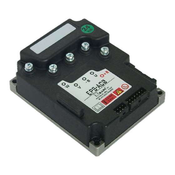
4.3.1 Eps-ac0 PCB It has Molex Minifit connector with international protection IP54. Figure 4-1 Page - 14/95 AEMZP0EA - EPS-AC0 SWs&ENC - User Manual... -
Page 15: Sensor In The Steering Handle
4.4 Sensor in the steering handle Two configurations are foreseen: 1) No limit, multiturn steering wheel. 2) Tiller, handlebar or joystick arrangement with a limited angle. Depending by the above choice, there are two different handling: 1) In case of multiturn steering wheel, a stepper motor is used (open loop mode). 2) In case of a handlebar with limited angle, a twin pot is used (closed loop mode). - Page 16 1) CONTELEC twin hall sensors 170° Type code VERT-X 2841 417 225. 2) BOURNS twin potentiometers 180° Type Code 6657S-466-502. 3) MCB twin potentiometers 85° Type Code PMR 410 or PMR426. The CONTELEC is without brushes but drains a high level of current (about 15 mA). The MCB has the advantage of a spring in the shaft.
-
Page 17: Feedback Sensors
4.5 Feedback sensors Feedback sensors are mandatory to close the loop in manual mode if a twin pot is mounted on the steering wheel. Feedback sensors are strongly suggested (to improve safety) in manual mode if a stepper motor is mounted on the steering wheel (open loop). Eps-ac0 may handle two different configurations for the feedback sensors: 1) Incremental encoder in the motor shaft together with a feedback potentiometer on the steered wheel. - Page 18 4.5.2.1 Straight ahead toggle switch The straight ahead toggle switch must be of NPN type (i.e. it must connect a minus battery to CNA#3). A possible arrangement for the straight-ahead switch (proximity switch) is shown in Figure 4-4- below. The proximity switch is connected to the truck frame; the Iron plate rotates together with the steered wheel.
- Page 19 AC motor control; it works completely sensorless. Following this statement, we have developed, together with a Zapi’s partner AC- motor-manufacturer, a 4 pulses/rev discrete encoder. It is an external device (not integrated in the ball bearing) mounted in the backside of the motor (see Figure 4-5 below showing a 300 W AC Motor by “Best Motor”...
- Page 20 EPSAC0=Eps-ac0 steering controller Open Loop (Stepper motor) poles pair number 32 pulses/rev encoder SW release type Zapi 0.70= SW release number 0.70 The command configuration is specified through the first letter after EPSAC0 in the following list: Open Loop (Stepper Motor)
-
Page 21: Connecting Diagrams
5 CONNECTING DIAGRAMS Below we have a collection of suggested connecting diagrams. They correspond to the main configurations. On request it is possible to choose also customized proposals or wiring modifications. 5.1 Power Connecting Diagram EPS-AC0 Figure 5-1 AEMZP0EA - EPS-AC0 SWs&ENC - User Manual Page - 21/95... -
Page 22: Eps-Ac0 Twin Pot Diagram
5.2 EPS-AC0 Twin pot diagram Figure 5-2 Page - 22/95 AEMZP0EA - EPS-AC0 SWs&ENC - User Manual... -
Page 23: Eps-Ac0 Stepper Motor Diagram
5.3 EPS-AC0 Stepper Motor diagram Figure 5-3 AEMZP0EA - EPS-AC0 SWs&ENC - User Manual Page - 23/95... -
Page 24: Connections: Suggestions And Cautions
6 CONNECTIONS: SUGGESTIONS AND CAUTIONS Read the following suggestions to get a correct connection of the steering equipment. 6.1 Stepper Motor connections The stepper motor has 4 connections: two are the stepper motor channels (CNA#9 and CNA#8) and two are the common (negative) references (CNA#10 and CNA#11). -
Page 25: Digital Inputs Connections
broken connection: when Vout overtakes 4.7 V or is lower than 0.3 V it is possible to raise an alarm. Figure 6-1 6.5 Digital Inputs connections There are three digital inputs available. Two of them (CNA#3 and CNA#2) must be GND connected to work properly. CNA#3 and CNA#2 are used for the toggle switches. -
Page 26: Motor Thermal Sensor Connections
when the key switch is turned on. The contact opens where there is a steering alarm. This safety contact is floating, that means it's possible to connect it either to the plus battery or to the minus battery. Ensure that the pin #5 is connected to an equal or higher voltage than pin #4. -
Page 27: Installation: Suggestions And Cautions
7 INSTALLATION: SUGGESTIONS AND CAUTIONS Read and respect the following suggestions to avoid problem during installation and in the definitive releasing. 7.1 Thermal consideration 1) The heat generated by the power block must be dissipated. For this to be possible the compartment must be ventilated and the heat sink materials ample. 2) Normally eps-ac0 does not ask for a forced ventilation: if the cooling is poor, a possible solution could be to redirect a part of the forced air flow of the traction controller toward the eps-ac0. -
Page 28: General Suggestion
7.2 General suggestion For a proper installation take care of the following recommendations: Never connect SCR low frequency chopper with AC Motor Inverter because the Rail capacitors alter the SCR choppers' work. If it is necessary to use two or more control units (e.g. traction + lift. + steering controller), they must belong to the ZAPIMOS family. -
Page 29: Contactors
7.5 Contactors According to EN1175 5.9.6, a contactor to cut the line to the eps-ac0 is not strictly required. In fact in an AC system, the steer is automatically de-energized when a power failure occurs. In a DC system with permanent magnet motor instead, a short circuit in a power device, gets the steering motor rotates at maximum speed (and so it is necessary to cut off the line from the controller). - Page 30 The eps-ac0 drains low level of current and so low section cables (4 mm ) are adopted for the power connections. This could be a drawback: in fact, a low section cable has higher reactance (impedance) than a wide section cable. As a consequence the noise generated on the minus battery cable, by the CAN lines switching, will be a wide amplitude spike.
- Page 31 Correct Layout: Can Bus Power cables Node 1 Node 2 Traction Lift Control Control Node 3 eps-ac0 The chain starts from the –BATT post of the controller that works with the highest current, and the others are connected in a decreasing order of power. Otherwise, if two controllers are similar in power (for example a traction and a pump motor controller) and a third module works with less current, the best way to deal this configuration is to create a common ground point (star configuration)
-
Page 32: Wiring: I/O Connections
ZAPI is always available to cooperate with the customer in order to evaluate installation and connection solutions. Furthermore, ZAPI is available to develop new SW or HW solutions to improve the safety of the machine, according to customer requirements. -
Page 33: Emc
Special attention must be given to the lengths and the paths of the electric connections and the shields. This situation is beyond ZAPI's control. Zapi can offer assistance and suggestions, based on its years experience, on EMC related items. However, ZAPI declines any responsibility for non-compliance, malfunctions and failures, if correct testing is not made. -
Page 34: Electromagnetic Immunity
7.9.2 Electromagnetic Immunity The electromagnetic immunity concerns the susceptibility of the controller to external electromagnetic fields and their influence on its correct work made. These tests are carried out at determined levels of electromagnetic fields, to simulate external undesired disturbances and verify the electronic device response. Here are some suggestions to improve the electromagnetic immunity: 1) SHIELDING: enclosing controller and wiring when possible on a shielded box;... -
Page 35: Fighting The Dither
It is strongly suggested to connect to the truck frame all the parts of the truck that can get in touch with the operator (who is most of the time the source of ESD). For example, we strongly suggest to connect the stepper motor frame to the truck frame. -
Page 36: How Can Steer Accuracy Be Improved? Minimizing Mechanical Plays
7.11 How can steer accuracy be improved? Minimizing mechanical plays The highlight of a correct installation for a steering system with potentiometers is to neutralize the mechanical plays. Due to the fact we have only a potentiometer in the tiller side, the mechanical play to be neutralized is the one in the shaft of the potentiometer at the tiller. -
Page 37: Description Of The Connectors
8 DESCRIPTION OF THE CONNECTORS EPS-AC0 Figure 8–1 8.1 Connectors of the logic Figure 8–2 AEMZP0EA - EPS-AC0 SWs&ENC - User Manual Page - 37/95... -
Page 38: Cna Connector
8.1.1 CNA connector DRIVE SWITCH Traction Travel Demand Input. Toggle Switch (90 degrees). Toggle Switch (0 degrees). Safety Switch Lower Voltage Point. Safety Switch Higher Voltage Point. CANL Can Bus Low. Key in. CPOC2 / QL SP POT Wiper or Stepper Motor Q line. CPOC1 / DL SP POT Wiper or Stepper Motor D line. -
Page 39: Description Of Power Connections
8.2 Description of power connections View of the power bars: EPS-AC0 Figure 8–3 Negative of the battery. Positive of the battery. U; V; W Connection bars of the three motor phases; follow this sequence and the indication on the motor. AEMZP0EA - EPS-AC0 SWs&ENC - User Manual Page - 39/95... -
Page 40: Installation Procedure
9 INSTALLATION PROCEDURE By setting FEEDBACK DEVICE to OPTION#4 and recycling the key, the encoder will be used in combination with one or two toggle switches to measure the steered wheel angle. The toggle switch in the straight ahead position (0 degrees) of the steered wheel is used to initialize the encoder counting. -
Page 41: Stepper Motor With Encoder And Toggle Switches. Steered Wheel With Mechanical Limitation: One Shot Installation Procedure
Step10 Verify the steered wheel rotates in the correct direction according to the steering wheel. If it isn’t, swap DL (CNA#9) with QL (CNA#8). To get the system properly working it is necessary to set the encoder counting for a whole steered wheel revolution together with the specification of the toggle switches arrangement (one or two toggle switches and their succession inside a complete steered wheel revolution). - Page 42 to get the prototype working in manual mode: to raise the AUTC function it is necessary to make the complete set-up procedure (see topic 10). For every truck released on the field, the correct installation set-up is already known (as it was determined from the test on the prototype) and so no installation procedure is required except for the quick set-up (see the quick set-up 10.2).
-
Page 43: Twin Pot With Encoder And Toggle Switches. Steered Wheel Without Mechanical Limitation: One Shot Installation Procedure
Step16 Procedure is finished. Don’t forget to turn the special adjustment DEBUG OUTPUT to level 15 if never done before. Step17 Carry out the complete set-up procedure (see 10.1). 9.3 Twin Pot with Encoder and Toggle switches. Steered wheel without mechanical limitation: one shot installation procedure This procedure is relative to the connecting drawings Figure 5-2. - Page 44 autoteaching function is the right mean for setting SET ENC AT 360 and AUX FUNCTION 11 (see below). Step12 Set special adjustment AUX FUNCTION 11 to level 0 or 1 if only one toggle switch is adopted; set AUX FUNCTION to level 2 to 5 if two toggle switches (0 degrees and 90 degrees) are adopted.
-
Page 45: Twin Pot With Encoder And Toggle Switches. Steered Wheel With Mechanical Limitation: One Shot Installation Procedure
chosen or in case it is not clear what the above statements mean, jump to Step 23 (procedure finished). Step18 Set option LIMIT DEVICE to OFF and recycle the key. Step19 Move the hand wheel until the wished maximum (in the direction of plus 90 degrees) steered wheel angle is achieved (Increase 1ST ANGLE COARSE - and FINE - if necessary). - Page 46 reading ENC SPEED in the tester menu is consistent with the reading FREQUENCY in the tester menu. Consistent means that ENC SPEED and FREQUENCY must have the same sign and a close value. If ENC SPEED is not close to FREQUENCY, the encoder resolution is wrong and it will be not possible to work with ENCODER CONTROL to ON (a different SW is needed in this case).
- Page 47 chosen or in case it is not clear what the above statements mean, jump to Step 22 (procedure finished). Step17 Set option LIMIT DEVICE to OFF and recycle the key. Step18 Move the hand wheel until the wished maximum (in the direction of plus 90 degrees) steered wheel angle is achieved (Increase 1ST ANGLE COARSE - and FINE - if necessary).
-
Page 48: Setting The Eps-Ac0
10.1.1 together with the following: Step1 When the autocentering (AUTC) is required, it is necessary to contact a Zapi technician to decide the physical and the superior protocol layers for the AUTC demanding. (AUTC is a customized function that the eps-ac0 does not execute in its standard version). -
Page 49: Twin Pot & Autc
10.1.3 together with the following: Step1 When the autocentering (AUTC) is required, it is necessary to contact a Zapi technician to decide the physical and the superior protocol layers for the AUTC demanding. (AUTC is a customized function that the eps-ac0 does not execute in its standard version). -
Page 50: Quick Set-Up
10.2 Quick set-up This procedure shall be executed on every manufactured truck. It changes with the configuration. 10.2.1 Stepper Motor without mechanical angle limitation We assume the special adjustment AUX FUNCTION 11 is correctly set in its default value. Then a single step set-up procedure is required. Step1 Set special adjustment AUTOTEACHING to ON and recycle the key. -
Page 51: Aux Function 11 Manual Setting
Step3 Then, the handle bar has a dead band around its straight ahead position. Drive the truck with the handle bar inside its dead band and roll-up or down the adjustments SET STEER 0-POS to get the truck straight travelling. (Pay attention: the dead band in the tiller fades away when switching off the key. -
Page 52: Set Enc At 360 Manual Setting
10.4 SET ENC AT 360 manual setting Skill person only. When the angle of the steered wheel has a mechanical limitation, it is not possible to perform the autoteaching procedure. Then it is necessary to manually set the encoder counting corresponding to a complete steered wheel revolution. -
Page 53: Manual Teaching
7) Check the readings have a consistent value (higher than 0V and lower than 5V. Close values are expected for truck of the same model). 8) If the right side value (ENC COUNT AT 180) is not in a window from 3/8 to 5/8 of the left side value (ENC COUNT AT 360), the display changes cyclically from those values to the DATA ACQUISITION inscription. -
Page 54: Programming & Adjustments Using Digital Console
11 PROGRAMMING & ADJUSTMENTS USING DIGITAL CONSOLE 11.1 Adjustments via console Adjustment of Parameters and changes to the inverter’s configuration are made using the Digital Console. The Console is connected to the CNC connector of the inverter. 11.2 Description of console (hand set) & connection Figure 11–1 Page - 54/95 AEMZP0EA - EPS-AC0 SWs&ENC - User Manual... -
Page 55: Description Of Standard Console Menu
Digital consoles used to communicate with AC inverter controllers must be fitted with EPROM CK ULTRA, minimum "Release Number 3.02". The section describes the Zapi hand set functions. Numbers inside the triangles correspond to the same number on the hand set keyboard buttons shown in the Figure 11-1. -
Page 56: Twin Pot With Encoder And Feedback Pot
11.3.2 Twin Pot with Encoder and Feedback pot Figure 11–3 11.4 Function configuration The functions list change with the settings SYSTEM CONFIG and FEEDBACK DEVICE (see 11.4.3.1 and 11.4.1.3). In particular, we will distinguish between the configurations with stepper motor against the one with Twin Pot in the hand wheel. In the next we refer to a complete list that is the union of the settings in the above configurations. -
Page 57: Config Menu "Set Options" Functions List
Then roll until the SET OPTION item appears on the hand set display. Push the ENTER button (see Figure 11-4). EPSAC0C2A ZP0.91 Opening Zapi Display 24V 50A 00000 Push ROLL UP + SET UP simultaneously to enter... - Page 58 1) HOUR COUNTER This option specifies the hour counter mode. It can be set one of two: RUNNING: The counter registers travel time only. KEY ON: The counter registers when the "key" switch is closed. 2) MICRO CHECK This option is useful to support debug and troubleshooting. It makes possible to inhibit the supervisor (Slave uC) operations and allows the system to run with just the Main uC.
- Page 59 6) DIAG MOTOR TEMP This option enables the diagnosis of the motor temperature. When it is set On and the motor temperature overtakes 150°, a MOTOR TEMPERAT alarm occurs. The KTY84-130 motor thermal sensor must be connected between CNB#3 and a minus battery (CNA#13).
-
Page 60: Config Menu "Adjustments" Functions List
Then roll until the ADJUSTMENTS item appears on the hand set display. Push the ENTER button (see the Figure 11-5 below). EPSAC0 S ZP0.70 1) Opening Zapi Menu 24V 50A 00000 2) Press Top Left & Right Buttons to enter % ' %... - Page 61 1) ADJUSTMENT #01 This setting is used to acquire the motor resistance (see 12.2). 2) SET CURRENT This setting is factory adjusted to calibrate the ADJUSTMENT #03 and #04 below. 3) ADJUSTMENT #02 Motor resistance in milliohms. This is the resistance of the motor measured between two motor terminals.
- Page 62 line connected to CNA#9. The default value is 2.500 mV and can be re-acquired by rolling the DEBUG OUTPUT to 0 (see 11.4.6.4). 12) AUX VOLTAGE #2 (Factory adjusted). This is the self-acquired offset value of the stepper motor line connected to CNA#8. The default value is 2.500 mV and can be re-acquired by rolling the DEBUG OUTPUT to 0 (see 11.4.6.4).
- Page 63 Autoteaching procedure automatically saves the new ENC COUNT AT 180 on SET ENC AT 180; manual teaching procedures asks the ENC COUNT AT 180 being manually saved on SET ENC AT 180. 17) ZERO SP POT (Twin Pot version only). This adjustment is used to self-acquire (see 10.1.3 and 10.2.3) the voltages on the twin potentiometers when the steer handle is released in its straight ahead position.
-
Page 64: Config Menu "Set Model" Functions List
Then roll until the SET MODEL item appears on the hand set display. Push the ENTER button (see the Figure 11-6 below). EPSAC0 S ZP0.70 1) Opening Zapi Menu 24V 50A 00000 2) Press Top Left & Right Buttons to enter... - Page 65 1) SYSTEM CONFIG Level 0 to 6. This setting is used to select the steer configuration (i.e. the open or closed loop mode and the type of command sensors) in the following combination list. LEVEL 0: Stepper motor with feedback sensor. This is an open loop configuration.
- Page 66 CAN Bus connected. With the hand-set connected to the eps-ac0 it is possible to communicate with a remote Zapi unit. Every Zapi unit has its own identification number (e.g. eps-ac0 is 6; traction controller is 2;...
-
Page 67: Main Menu "Parameter Change" Functions List
To enter the MAIN MENU it is just necessary to push the ENTER button from the home display in the hand set. EPSAC0 S ZP1.93 1) Opening Zapi Menu 24V 50A 00000 ' % ' 2) Press ENTER to go into the General Menu... - Page 68 1) SPEED LIMIT (Stepper Motor version only). Level 0 to 9. It determines the scaling factor between the speed of the steering wheel and the speed of the steering motor but only when the steering wheel is fast turning. By increasing the SPEED LIMIT value, the steering motor speed increases too.
- Page 69 5) AUX FUNCTION #2 Depending on the configuration, this parameter has different meaning. Twin Pot version: Level 0 to 9. This setting performs the Dynamic Numbness compensation: it consists of a reduction in the steer sensitivity when the truck is driving at high speed.
- Page 70 correspondence between the steering motor speed and the angle error between the actual commanded position and the latest steady state position of the steered wheel: when this angle error is wider than the angle specified with this setting, there will be no clamp on the steering motor speed (full speed steering motor is SET SAT FREQ plus OVERSAT FREQ);...
- Page 71 11) AUXILIARY TIME This parameter defines the time, after the steer handle is released and the travel demand deactivated, for which the stand still torque is applied. LEVEL 0: No stand still torque. LEVEL 1: Brief application of the stand still torque (about 6 secs). LEVEL 9: Long application of the stand still torque (about 90 secs).
- Page 72 steered wheel angle in the direction where FEEDBACK ENC is lower than 2.5 V. It is used in closed loop application only (Twin pot) and it is a scaling factor between the SET POINT POT reading and the FEEDBACK ENC reading. By increasing this parameter, the maximum steered wheel angle increases too.
-
Page 73: Zapi Menu "Hardware Settings" Functions List
11.4.5 Zapi menu “HARDWARE SETTINGS” functions list To enter this Zapi hidden menu a special procedure is required. Ask this procedure directly to a Zapi technician. 1) MAXIMUM CURRENT MAXIMUM CURENT sets the limit for the current in the controller. - Page 74 OFF and ENDSTROKE ACW (corresponding to CNA#2) is ON when the WHEEL ANGLE is in the window 0 to 90 degrees). LEVEL 4: two toggle switches in the straight ahead and 90 degrees position. ENDSTROKE CW (corresponding to CNA#3) is ON and ENDSTROKE ACW (corresponding to CNA#2) is OFF when the WHEEL ANGLE is in the window 0 to 90 degrees).
-
Page 75: Zapi Menu "Special Adjustment" Functions List
11.4.6 Zapi menu “SPECIAL ADJUSTMENT” functions list To enter this Zapi hidden menu a special procedure is required. Ask this procedure directly to a Zapi technician. 1) HIGH ADDRESS Zapi reserved. 2) SET TEMPERATURE Factory adjusted. 3) MAX SP SLOPE (Twin pot version only). -
Page 76: Main Menu "Tester" Functions List
LEVEL 1-9 Zapi reserved. LEVEL 10: Enables the NO LOAD CURRENT test (see 11.4.2.10). Roll from level 10 to level 15 and save the new setting to exit this testing condition. LEVEL 11: Disables the alarms FB SENS LOCKED and MOTOR LOCKED till a new DEBUG OUTPUT hand setting. - Page 77 The steered wheel is in the 1 sector (FEEDBACK SECTOR to 3.13V) when the configuration of the toggle switch is the one expected for a steered wheel angle in the range 0 to 180 degrees. The steered wheel is in the 4 sector (FEEDBACK SECTOR to 1.88V) when the configuration of the toggle switch is the one expected for a steered wheel angle in the range -180 to 0 degrees.
- Page 78 LIMIT DEVICE to ON) and the FEEDBACK ENC overtakes the superior limit for the steered wheel angle limitation, the steered wheel angle will be limited and CW LIMIT LEVEL turns ON (active). 15) ACW LIMIT LEVEL When the maximum angle limitation via feedback sensors is enabled (option LIMIT DEVICE to ON) and the FEEDBACK ENC is lower than the inferior limit for the steered wheel angle limitation, the steered wheel angle will be limited and ACW LIMIT LEVEL turns ON (active).
- Page 79 The SLOPE PEAK measurement is the difference between two AD conversions of the selected potentiometer picked up with 16 msec long interval. The SLOPE PEAK reading can be converted in a Voltage change (∆V in volts) of the wiper voltage in an interval 16 msec long, with the formula: ∆V = SLOPE PEAK*5/1024 = Voltage change in Volts in 16 msec (e.g.
-
Page 80: Special Functions
12 SPECIAL FUNCTIONS Here is a list of special functions hand set assisted, that are not documented yet. 12.1 Not CAN Bus assisted application Eps_ac0 may work in a stand alone configuration (not CAN Bus assisted). Two operations are required in this case: 1) Set CAN BUS in the hardware setting menu to ABSENT (see 11.4.5.2) and recycle the key. -
Page 81: Straight Ahead Steering Numbness
has a drift with a released steering wheel. To enable this function, turn RECOVERY AT REST to On and recycle the key (see 11.4.1.10). This alignment at the rest position is handled closed loop. 12.4 Straight ahead steering numbness In closed loop applicant (twin pot at the handle bar) It is possible to reduce the steering sensitivity while the steered wheel is close to be straight ahead by using the NUMBNESS setting in the PARAMETERS CHANGE menu. -
Page 82: Refresh Of The Encoder Counting
Together with this possibility DEBUG OUTPUT provides many other special functions (that are described in paragraph 11.4.6.4). For example it is possible to use the hand set to read the voltage from the second twin pot wiper (CPOC2 on CNA#8) on the reading SET POINT POT of the hand set. It is just enough to turn DEBUG OUTPUT to level 13. -
Page 83: Eps-Ac0 Alarms List
13 EPS-AC0 ALARMS LIST The ALARMS logbook in the MAIN MENU records the alarms of the controller. It has a FIFO (First Input First Output) structure that means the oldest alarm is lost when the database is full and a new alarm occurs. The logbook is composed of five locations getting possible to stack five different types of alarms with the following information: 1) The alarm code... - Page 84 - Cause: It occurs two ways: a) In steady state condition, when the main uC finds the safety contact controlled by the slave uC has been opened, but no alarm information has been communicated from the slave uC to justify the opening of the safety contact.
- Page 85 9) KM CLOSED CAN Bus Code = 253 - Cause: This alarm occurs at key on if the slave uC detects the safety contact, of the main uC, closed prior to be commanded. - Remedy: This alarm occurs if the connection CNA#5 (K1) is around a voltage of 12 Vdc when switching on the key.
-
Page 86: Two Blinks Alarms
16) SL CENTERING CAN Bus Code = 213 - Cause: This alarm occurs when an automatic centering is requested from steady state condition. Then the slave uC expects the angle measured on the steered wheel goes into a window from -20 to +20 degrees before the traction turns moving. -
Page 87: Three Blinks Alarms
- Remedy: It is necessary to replace the controller. 7) MAIN CONT. OPEN CAN Bus Code = 48 - Cause: This alarm occurs only when the setting CAN BUS is PRESENT. Then the eps-ac0 waits for a via CAN information that the traction controller has closed the main contactor. - Page 88 wiper (CPOC1) exits the range from 0.8 Vdc to 4.2 Vdc. When the twin pot is chosen, the alarm occurs if the sum of the two wiper voltages (CPOC1+CPOC2) exits the range from 4.5 Vdc to 5.5 Vdc. - Remedy: Check the connections of the potentiometer.
- Page 89 plate on the steered wheel. 2) A ring of the sensor bearing has a slip (the sensor bearing has two rings: one is connected to the rotor shaft; the other is connected to the motor frame. Check these two rings are strictly connected to their structure without slip).
-
Page 90: Four Blinks Alarms
If the values in these three locations are different in between this alarm occurs. - Remedy: It is necessary to send the controller to Zapi to execute the maximum current regulation. 3) CURRENT GAIN CAN Bus Code = 225... -
Page 91: Six Blinks Alarms
13.1.6 Six Blinks Alarms 1) STBY I HIGH CAN Bus Code = 53 - Cause: This alarm occurs two ways: 1) In the initial rest state after key on, if the outputs of the current amplifiers are not comprised in the window 2.2 to 2.8 Vdc. 2) After the initial diagnosis this alarm occurs when the outputs of the current amplifiers at rest have a drift larger than ±0.15 V. -
Page 92: Can Bus "Alarms" List
2) WAITING DATA CAN Bus Code = 237 - Cause: This warning occurs only if CAN BUS is PRESENT. At key-on the eps-ac0 asks to the traction controller to send a list of parameters via CAN Bus. From the request until the parameters are correctly relieved, this warning occurs. - Page 93 225: CURRENT GAIN 226: NO SYNC 227: SLAVE COM. ERROR 228: POSITION ERROR 237: WAITING DATA 238: EPS NOT ALIGNED 239: WAITING FOR TRAC 241: ENCODER ERROR 242: Q LINE SENSOR KO 243: D LINE SENSOR KO 244: GAIN EEPROM KO 245: DATA ACQUISITION 246:...
-
Page 94: Recommended Spare Parts
14 RECOMMENDED SPARE PARTS Part number Description C36090 Stepper motor minebea E07161 Twin pot C38207 Best motor 300 W AC motor and P62 IMS gear box 1:51 C12414 Molex Minifit Connector 8 pins Female C12403 Molex Minifit Connector 14 pins Female C12777 Female Molex Minifit pin harness side Page - 94/95... -
Page 95: Periodic Maintenance To Be Repeated At Times Indicated
During periodic checks, if a technician finds any situation that could cause damage or compromise safety, the matter should be bought to the attention of a Zapi Agent immediately. The Agent will then take the decision regarding operational safety of the machine.
Need help?
Do you have a question about the EPS-AC0 SWs&ENC and is the answer not in the manual?
Questions and answers