Table of Contents

Related Manuals for Zapi EPS-AC0


Summary of Contents for Zapi EPS-AC0
- Page 1 ELECTRONIC • OLEODYNAMIC • INDUSTRIAL EQUIPMENTS CONSTRUCTION Via Parma, 59 – 42028 – POVIGLIO (RE) – ITALY Tel +39 0522 960050 (r.a.) – Fax +39 0522 960259 e-mail: zapi@zapispa.it – web: www.zapispa.it User Manual EPS-AC0...
- Page 2 Under no circumstances will Zapi S.p.A. be held responsible to third parties for damage caused by the improper use of the present publication and of the device/devices described in it. Zapi spa reserves the right to make changes or improvements to its products at any time and without notice.
-
Page 3: Table Of Contents
Feedback Encoder ..................18 AUTC MODE........................21 CONNECTING DIAGRAMS....................22 Power Connecting Diagram ..................22 EPS-AC0 Stepper Motor diagram ................23 EPS-AC0 Twin pot diagram..................24 CONNECTIONS: SUGGESTIONS AND CAUTIONS ............25 Stepper Motor connections ..................25 Twin pot connections....................25 Encoder connections .................... - Page 4 Config menu “SET MODEL” functions list ..........65 12.4.4 Main menu “PARAMETER CHANGE” functions list........68 12.4.5 Zapi menu “HARDWARE SETTINGS” functions list ........75 12.4.6 Zapi menu “SPECIAL ADJUSTMENT” functions list ........76 12.4.7 Main menu “TESTER” functions list ............78 13 OTHER FUNCTIONS ......................
- Page 5 16 PERIODIC MAINTENANCE TO BE REPEATED AT TIMES INDICATED......95 16.1 Testing the faulty detection circuitry ................. 95 APPROVAL SIGNS COMPANY FUNCTION INIZIALS SIGNS PROJECT MANAGER TECHNICAL ELECTRONIC MANAGER VISA SALES MANAGER VISA Publication N°: AEMZP0BA Edition: May 2006 AEMZP0BA - EPS-AC0 - User Manual Page - 5/95...
-
Page 6: Introduction
The on board CAN interface makes the communication exchange between our eps-ac0 and other units in the truck rapid and simple. Via CAN it is possible to enhance the steering performances with additional functions like: steer sensitivity changes with the traction speed, traction speed modulation vs. -
Page 7: Specification
2.2 Block diagram Figure 2-1 2.3 Electrical specifications Battery Voltage: ..................24 V-36 V Maximum current (24 V-36 V):............. 50 A (RMS) for 2' Logic Supply current: ..............max 200 mA @ 24 V AEMZP0BA - EPS-AC0 - User Manual Page - 7/95... -
Page 8: Mechanical Specifications
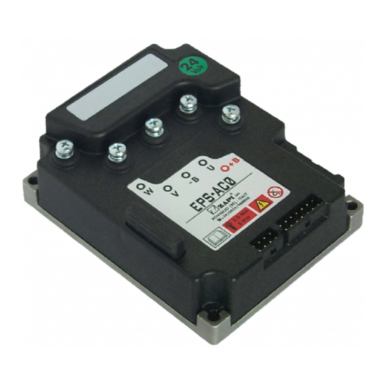
Minimum Input (key) Supply Voltage after start-up:..........12 V 2.4 Mechanical specifications 2.4.1 Basic release It has Molex Minifit connector with international protection IP54. EPS-AC0 Figure 2–2 Page - 8/95 AEMZP0BA - EPS-AC0 - User Manual... -
Page 9: Functions Of The Eps-Ac0
3 FUNCTIONS OF THE EPS-AC0 The eps-ac0 controls a steer system for warehouse trucks. It executes the following functions: 1) Manual mode steering 2) Automatic Centering. 3.1 Manual Mode Steering Manual mode steering requires a command sensor in the hand wheel. The hand wheel may be of two types: 1) Multiturn steering wheel without end-strokes. -
Page 10: Automatic Centering
(see 12.4.3.1). 3.2 Automatic Centering Automatic Centering turns the steered wheel straight ahead to keep the steer aligned meanwhile travelling inside an aisle between rails (see Figure 3-3). Figure 3–3 Page - 10/95 AEMZP0BA - EPS-AC0 - User Manual... -
Page 11: Operational Features
3.3 Operational features A list of eps-ac0 operational features follows below: 1) Static sensitivity boost in open loop (steering sensitivity increases for a slow moving steering wheel). 2) Static numbness in closed loop (steering sensitivity decreases for handle steer close to the straight-ahead direction). -
Page 12: System Components
4 SYSTEM COMPONENTS The eps-ac0 controller needs some external parts in order to work. The following list describes the complete equipment. 4.1 Steering Motor The steering system includes a three phase AC induction motor. The motor rated power (S2-1h) changes with the truck type. As a thumb rule: 1) A low level OP asks a motor with rated power higher than 250 W @ 3000 rpm. -
Page 13: Eps-Ac0 Pcb
4.3.1 Eps-ac0 PCB It has Molex Minifit connector with international protection IP54. Figure 4–1 AEMZP0BA - EPS-AC0 - User Manual Page - 13/95... -
Page 14: Sensor In The Steering Handle
2) JAPAN SERVO Type Code KH56JM2X 1269 DC12V 30 ohm. They have the same mechanical dimensions (see Figure 4.2 below). Obviously, the above information states only these parts are suited for the eps-ac0; no reliability evaluation is given here. Other sources are possible on request, but must be tested for approval. -
Page 15: Feedback Sensors
2) Incremental encoder in the motor shaft together with one (or two) toggle switch(es) in the straight ahead (and 90 degrees) position of the steered wheel. On request, in the closed loop application only, eps-ac0 may work also with two encoders in the motor shaft together with a straight ahead toggle switch. - Page 16 Normally the feedback potentiometer is multiturn (5 or 10 turns) 5K hybrid technology mounted on the output shaft of the steering gearbox (see Figure 4-4). Page - 16/95 AEMZP0BA - EPS-AC0 - User Manual...
-
Page 17: Encoder In The Motor Shaft And One (Two) Toggle Switch(Es)
A possible arrangement for the straight-ahead switch (proximity switch) is shown in Figure 4-6 below. The proximity switch is connected to the truck frame; the Iron plate rotates together with the steered wheel. Figure 4-6 AEMZP0BA - EPS-AC0 - User Manual Page - 17/95... -
Page 18: Feedback Encoder
It is handled this way: 1) At key-on, the eps-ac0 turns the steering motor moving in either CW or CCW side, according to whether the output level from the straight ahead switch is high or low (in the above sketch a proximity sensor is used as a straight ahead switch). - Page 19 Stepper Motor Twin Pot via CAN Bus Position via CAN Bus Speed The encoder resolution is given by the last letter before of the SW release in the following list: AEMZP0BA - EPS-AC0 - User Manual Page - 19/95...
- Page 20 48 pulses/rev 64 pulses/rev The letters to specify the poles pair number and the Encoder resolution are present only if the SW includes the function for controlling the motor with the encoder. Page - 20/95 AEMZP0BA - EPS-AC0 - User Manual...
-
Page 21: Autc Mode
5 AUTC MODE Eps-ac0 may perform an automatic centering operation (AUTC). AUTC means the steered wheel shall be aligned straight-ahead following a centering request. The centering request can be provided via CAN Bus. As alternative, it is possible to use wired requests. For example:... -
Page 22: Connecting Diagrams
Below we have a collection of suggested connecting diagrams. They correspond to the main configurations. On request it is possible to choose also customized proposals or wiring modifications. 6.1 Power Connecting Diagram EPS-AC0 Figure 6-1 Page - 22/95 AEMZP0BA - EPS-AC0 - User Manual... -
Page 23: Eps-Ac0 Stepper Motor Diagram
6.2 EPS-AC0 Stepper Motor diagram Figure 6-2 AEMZP0BA - EPS-AC0 - User Manual Page - 23/95... -
Page 24: Eps-Ac0 Twin Pot Diagram
6.3 EPS-AC0 Twin pot diagram Figure 6-3 Page - 24/95 AEMZP0BA - EPS-AC0 - User Manual... -
Page 25: Connections: Suggestions And Cautions
When a feedback pot is adopted it will be connected between CNB#2 (PPOT: positive supply), CNB#1(NPOT: negative supply), CNB#6 (CPOT: wiper). Pay attention, inside the eps-ac0, a 470 ohms resistance is connected between PPOT and 5 V supply and also between NPOT and the minus battery. That is done... -
Page 26: Digital Inputs Connections
CAN#1 is detected low if it is lower than 1.3 V. CNA#1 is detected high if it is open or higher than 3.3 V. Page - 26/95 AEMZP0BA - EPS-AC0 - User Manual... -
Page 27: Safety Contacts
Figure below). 7.7 Motor thermal sensor connections Eps-ac0 handles a motor thermal sensor: it should be KTY184-130 type. Through this sensor, the eps-ac0 measures the motor temperature: when DIAG MOTOR TEMP is set ON, and the motor temperature overtakes 150 degrees, an alarm occurs. -
Page 28: Installation: Suggestions And Cautions
2) Normally eps-ac0 does not ask for a forced ventilation: if the cooling is poor, a possible solution could be to redirect a part of the forced air flow of the traction controller toward the eps-ac0. -
Page 29: General Suggestion
2) For power connections to the motor and to the battery, use cables having section of 4-6 mm² (as a minimum). 3) The power cables length must be as short as possible to minimize power losses. AEMZP0BA - EPS-AC0 - User Manual Page - 29/95... -
Page 30: Fuses
2) Use a 32 A fuse for protection of the power stage. 8.5 Contactors According to EN1175 5.9.6, a contactor to cut the line to the eps-ac0 is not strictly required. In fact in an AC system, the steer is automatically de-energized when a power failure occurs. -
Page 31: Installation Of A Can Communication System
The eps-ac0 drains low level of current and so low section cables (4 mm ) are adopted for the power connections. - Page 32 The red lines are can wires. The black boxes are different modules, for example traction controller, pump controller and eps-ac0 connected by can bus. The black lines are the power cables. This is apparently a good layout, but can bring to errors in the can line.
-
Page 33: Wiring: I/O Connections
After crimping the cable, verify that all strands are entrapped in the wire barrel. Verify that all the crimped contacts are completely inserted on the connector cavities. For information about the mating connector pin assignment see the description of the connectors in topic 9. AEMZP0BA - EPS-AC0 - User Manual Page - 33/95... -
Page 34: Safety Features
ZAPI is always available to cooperate with the customer in order to evaluate installation and connection solutions. Furthermore, ZAPI is available to develop new SW or HW solutions to improve the safety of the machine, according to customer requirements. -
Page 35: Emission
In forklift trucks applications, special attention should be adopted for avoiding ESD. The main rule is that it is always much easier and cheaper to avoid ESD from being generated, than to increase the level of immunity of the electronic devices. AEMZP0BA - EPS-AC0 - User Manual Page - 35/95... -
Page 36: Fighting The Dither
Obviously, both the potentiometers (SP POT and FB POT) have noise and contribute to the problem. There are some countermeasures to reduce or neutralize the dither. Page - 36/95 AEMZP0BA - EPS-AC0 - User Manual... - Page 37 1) Use shielded cable for the connections of the potentiometers (especially for the SP POT). The shielded cable reduces the noise in the wiper voltage. Connect the shield to a GND pin of the eps-ac0 connectors. 2) Use the FB ENC instead of the FB POT as feedback sensor. The Encoder has not noise.
-
Page 38: Description Of The Connectors
9 DESCRIPTION OF THE CONNECTORS EPS-AC0 Figure 9–1 Page - 38/95 AEMZP0BA - EPS-AC0 - User Manual... -
Page 39: Connectors Of The Logic
9.1.2 CNB connector NPOT FB POT Negative Supply. PPOT FB POT Positive Supply. THMOT Motor Thermal Sensor (KTY84-130) Input. +5VDC Encoder Positive Supply. PPOC Twin SP POT Positive Supply (5 Vdc). AEMZP0BA - EPS-AC0 - User Manual Page - 39/95... -
Page 40: Cnc Connector
Negative console power supply. Positive console power supply. FLASH Must be connected to C8 for the Flash memory programming (if used). FLASH Must be connected to C7 for the Flash memory programming (if used). Page - 40/95 AEMZP0BA - EPS-AC0 - User Manual... -
Page 41: Description Of Power Connections
View of the power bars: EPS-AC0 Figure 9–3 Negative of the battery. Positive of the battery. U; V; W Connection bars of the three motor phases; follow this sequence and the indication on the motor. AEMZP0BA - EPS-AC0 - User Manual Page - 41/95... -
Page 42: Installation Procedure
When a FB POT LOCKED alarm occurs immediately after switching on the key, it means the motor is turning away from the wished position (i.e. FEEDBACK POT decreases when the FREQUENCY is Page - 42/95 AEMZP0BA - EPS-AC0 - User Manual... -
Page 43: Twin Pot With Encoder, Straight Ahead Switch And Feedback Pot: One Shot Installation Procedure
AUTC function it is necessary to make the complete set-up procedure (see topic 11). AEMZP0BA - EPS-AC0 - User Manual Page - 43/95... - Page 44 Step15 With the steered wheel in the minimum angle (minus 90 degrees), enter and save the adjustment SET MIN FB POT on the hand set to memorize the steer angle feedback pot voltage for the minimum (minus 90 degrees) limit Page - 44/95 AEMZP0BA - EPS-AC0 - User Manual...
-
Page 45: Stepper Motor With Encoder And Feedback Pot: One Shot Installation Procedure
ERROR due to the unknown scaling between the encoder counting and the feedback pot value before of an encoder learning operation - Step 12 and 14 below). Step4 Set option ENCODER CONTROL to OFF. AEMZP0BA - EPS-AC0 - User Manual Page - 45/95... -
Page 46: Stepper Motor With Encoder And Toggle Switch(Es): One Shot Installation Procedure46
For every truck released on the field, the default set-up and wiring shall reply the prototype settings and so no installation procedure is required except for the acquisition of the limiting position (see the quick set-up 11.2). Carry out the procedure in the following order. Page - 46/95 AEMZP0BA - EPS-AC0 - User Manual... - Page 47 (first sector). Read the ENDSTROKE CW and ENDSTROKE ACW in the tester menu. Set AUX FUNCTION 11 to the proper level as specified below: ENDSTROKE CW=OFF and ENDSTROKE ACW=OFF: Level 2 AEMZP0BA - EPS-AC0 - User Manual Page - 47/95...
- Page 48 Step20 Don’t forget to turn the special adjustment DEBUG OUTPUT to level 15 after finished the setting procedure to enable the POSITION ERROR test between encoder counting and toggle switches sector. Recycle the key. Step21 Carry out the complete set-up procedure (see 11.1). Page - 48/95 AEMZP0BA - EPS-AC0 - User Manual...
-
Page 49: Setting The Eps-Ac0
11.1.1 together with the following: Step1 When the autocentering (AUTC) is required, it is necessary to contact a Zapi technician to decide the physical and the superior protocol layers for the AUTC demanding. (AUTC is a customized function that the eps-ac0 does not execute in its standard version). -
Page 50: Rtc & Autc
11.1.3 together with the following: Step1 When the autocentering (AUTC) is required, it is necessary to contact a Zapi technician to decide the physical and the superior protocol layers for the AUTC demanding. (AUTC is a customized function that the eps-ac0 does not execute in its standard version). -
Page 51: Stepper Motor & Autc
ZERO SP POT (to record the rest twin pot voltage). Step2 Roll-up or down the adjustments SET STEER 0-POS to get the truck straight travelling when the handlebar is straight ahead. AEMZP0BA - EPS-AC0 - User Manual Page - 51/95... -
Page 52: Programmaing & Adjustments Using Digital Console
Adjustment of Parameters and changes to the inverter’s configuration are made using the Digital Console. The Console is connected to the CNC connector of the inverter. 12.2 Description of console (hand set) & connection Figure 12–1 Page - 52/95 AEMZP0BA - EPS-AC0 - User Manual... -
Page 53: Description Of Standard Console Menu
Digital consoles used to communicate with AC inverter controllers must be fitted with EPROM CK ULTRA, minimum "Release Number 3.02". The section describes the Zapi hand set functions. Numbers inside the triangles correspond to the same number on the hand set keyboard buttons shown in the Figure 12-1. -
Page 54: Stepper Motor With Encoder And Feedback Pot
12.3.1 Stepper motor with Encoder and Feedback pot Figure 12–2 Page - 54/95 AEMZP0BA - EPS-AC0 - User Manual... -
Page 55: Rtc With Encoder And Feedback Pot
12.3.2 RTC with Encoder and Feedback pot Figure 12–3 AEMZP0BA - EPS-AC0 - User Manual Page - 55/95... -
Page 56: Stepper Motor With Encoder And Toggle Switch(Es)
12.3.3 Stepper motor with Encoder and Toggle switch(es) Figure 12-4 Page - 56/95 AEMZP0BA - EPS-AC0 - User Manual... -
Page 57: Function Configuration
In the next we refer to a complete list that is the union of the settings in the above configurations. When the setting refers to only one configuration, it will be specified in the description. AEMZP0BA - EPS-AC0 - User Manual Page - 57/95... -
Page 58: Config Menu "Set Options" Functions List
' % ' CONFIG MENU The Display will show : SET OPTIONS SET OPTIONS Press OUT again. Display now will show the ' ' ' ' % ' opening Zapi menu Figure 12–5 Page - 58/95 AEMZP0BA - EPS-AC0 - User Manual... - Page 59 ON, the steered wheel angle will be limited using the feedback sensor value. It can be set one of two: When the feedback sensor overtakes either the CW or the CCW limit (see 12.4.2.13-14, SET MAX FB POT, SET MIN AEMZP0BA - EPS-AC0 - User Manual Page - 59/95...
- Page 60 Normally it is set OFF. When glitches are heard from the motor, it is necessary to turn to a sensored control. In this case set ENCODER CONTROL to On. Then, take care the encoder resolution used in the software (see 4.5.3) is Page - 60/95 AEMZP0BA - EPS-AC0 - User Manual...
- Page 61 FB POT. When it is OFF, the steered wheel seeks the falling edge during an initial automatic rotation in the direction of a decreasing FB POT. (A properly setting of POT UP SW1 EDGE is required to avoid EPS NOT ALIGN alarm). AEMZP0BA - EPS-AC0 - User Manual Page - 61/95...
-
Page 62: Config Menu "Adjustments" Functions List
11) Press OUT ' % ' ' % ' 12) Press ENTER to confirm ' ' ' 13) Repeat the same from 5 to 12 points for the other adjustments Figure 12–6 Page - 62/95 AEMZP0BA - EPS-AC0 - User Manual... - Page 63 SET SAT FREQ/2. 11) AUX VOLTAGE #1 (Factory adjusted). This is the self-acquired offset value of the stepper motor line connected to CNA#9. The default value is 2.500 mV and can be re-acquired AEMZP0BA - EPS-AC0 - User Manual Page - 63/95...
- Page 64 READ FBPT AT SW1 is expected to reply the SET FBPOT AT SW1 value. When a displacement exists between these two values, a POSITION ERROR alarm may occur (see 14.1.3.5). Page - 64/95 AEMZP0BA - EPS-AC0 - User Manual...
-
Page 65: Config Menu "Set Model" Functions List
9) Press OUT ' % ' ' % ' 10) Press ENTER to confirm ' ' ' 11) Repeat the same from 5 to 10 points for the other adjustments Figure 12–7 AEMZP0BA - EPS-AC0 - User Manual Page - 65/95... - Page 66 When these conditions are met, the FEEDBACK DEVICE option (see 12.4.1.3) specifies which kind of feedback sensor is adopted for the secondary Page - 66/95 AEMZP0BA - EPS-AC0 - User Manual...
- Page 67 In fact eps-ac0 has two uCs aboard. When MODEL TYPE is set to 0, the hand set is communicating with the main uC; when MODEL TYPE is set to 1, the hand set is communicating with the slave uC.
-
Page 68: Main Menu "Parameter Change" Functions List
NO=OUT 12) Press ENTER to accept the changes, or press ' ' ' ' % ' OUT to discard them MAIN MENU 13) The Display will show PARAMETER CHANGE Figure 12–8 Page - 68/95 AEMZP0BA - EPS-AC0 - User Manual... - Page 69 AUX FUNCTION #3 to Level 9 means maximum attenuation of the scaling factor with the truck speed. Obviously, to perform the Dynamic Numbness compensation, it is necessary to know the drive speed and so the eps-ac0 must be CAN Bus connected. AEMZP0BA - EPS-AC0 - User Manual Page - 69/95...
- Page 70 Obviously, to perform the Dynamic Numbness compensation, it is necessary to know the drive speed and so the eps-ac0 must be CAN Bus connected. 6) KP Level 0 to 9. It is used to set the proportional contribution to a PID algorithm for RTC and AUTC functions.
- Page 71 Compensate the drop on power mosfet, cables and motor resistance. COMPENSATION to LEVEL 2 is strongly suggested (the correct setting of the motor resistance is required when COMPENSATION is set to LEVEL 2-see 13.1). AEMZP0BA - EPS-AC0 - User Manual Page - 71/95...
- Page 72 This parameter regulates in coarse steps the maximum steered wheel angle in the direction where FEEDBACK ENC is lower than 2.5 V. It is a scaling factor between the SET POINT POT reading and the FEEDBACK ENC reading. Page - 72/95 AEMZP0BA - EPS-AC0 - User Manual...
- Page 73 RTC and AUTC functions. The derivative contribution is applied to the FEEDBACK ENC value only. High LEAD FB REGULAT value brakes the steering motor in advance respect to the commanded position so avoiding the AEMZP0BA - EPS-AC0 - User Manual Page - 73/95...
- Page 74 LEVEL 0: lowest lead contribution (overshooting is favourite). LEVEL 9: highest lead contribution (damping is favourite). Page - 74/95 AEMZP0BA - EPS-AC0 - User Manual...
-
Page 75: Zapi Menu "Hardware Settings" Functions List
12.4.5 Zapi menu “HARDWARE SETTINGS” functions list To enter this Zapi hidden menu a special procedure is required. Ask this procedure directly to a Zapi technician. 1) MAXIMUM CURRENT MAXIMUM CURENT sets the limit for the current in the controller. -
Page 76: Zapi Menu "Special Adjustment" Functions List
12.4.6 Zapi menu “SPECIAL ADJUSTMENT” functions list To enter this Zapi hidden menu a special procedure is required. Ask this procedure directly to a Zapi technician. 1) HIGH ADDRESS Zapi reserved. 2) SET TEMPERATURE Factory adjusted. 3) MAX SP SLOPE (RTC version only). - Page 77 POSITION ERROR (the latest only for FB ENC & TOGGLE SWs configuration). It switches automatically to the default Level 15 recycling the key. LEVEL 15: Default value (no special functions activated). AEMZP0BA - EPS-AC0 - User Manual Page - 77/95...
-
Page 78: Main Menu "Tester" Functions List
The minimum flux is Vbattery/(1.33*SET SAT FREQ). When the motor is loaded, SAT. FREQ HZ is equal to SET SAT FREQ; when the motor is lightened the flux reduces and SAT. FREQ HZ increases up to 1.33*SET SAT FREQ. Page - 78/95 AEMZP0BA - EPS-AC0 - User Manual... - Page 79 ACW LIMIT LEVEL turns ON (active). 17) AUTO IN PROGRESS Provides real time the information the eps-ac0 follows the manual command (AUTO IN PROGRESS is OFF) or is executing an automatic centering (AUTO IN PROGRESS is ON).
- Page 80 23) SLOPE PEAK This reading is just for debugging the maximum slope of the potentiometers connected to the eps-ac0. Especially when a reduced sensor equipment is chosen (just a single command potentiometer or just a single feedback potentiometer without encoder), a concern regarding the safety raises: if a single potentiometer fails a sudden movement of the steered wheel may occur with danger.
- Page 81 It is scaled in the range 0 to ±5 V with the meaning that 5 V corresponds to an encoder counting of 2 events. The ENC COUNT AT 360 absolute value can be recorded on the adjustment SET ENC AT 360. AEMZP0BA - EPS-AC0 - User Manual Page - 81/95...
-
Page 82: Other Functions
Eps-ac0 provides a self-acquisition procedure to acquire the motor resistance. It is just enough to connect the eps-ac0 to the battery, to the motor and to the wiring in order no alarm occurs. Then: 1) Enter the ADJUSTMENTS menu searching for ADJUSTMENT #01 setting. -
Page 83: Special Debugging And Troubleshooting System
It is difficult to find the root for the problem in the short time before the alarm occurs. For this reason the eps-ac0 provides a method to temporary inhibit these alarms. It is just enough to set the special adjustment DEBUG OUTPUT to Level 11. -
Page 84: Eps-Ac0 Alarms List
It occurs when the information on the status bus between the main uC and the slave uC is frozen to the 0xFF value (the slave uC does not update the status bus configuration). - Remedy: It is necessary to replace the controller. Page - 84/95 AEMZP0BA - EPS-AC0 - User Manual... - Page 85 K1 is expected being connected to a battery voltage (not 12 V). Search for a harness problem or replace the controller. 10) KM OPEN CAN Bus Code = 251 AEMZP0BA - EPS-AC0 - User Manual Page - 85/95...
-
Page 86: Two Blinks Alarms
- Remedy: Check the motor is suited to work with the eps-ac0 (not oversized). Otherwise it is necessary to replace the controller. 2) POWER FAILURE #1... -
Page 87: Three Blinks Alarms
- Cause: This alarm occurs only when the setting CAN BUS is PRESENT. Then the eps-ac0 waits for a via CAN information that the traction controller has closed the main contactor. If this information lacks more than about 1.5 secs, this alarm occurs. - Page 88 FEEDBACK SECTOR reading in the tester menu; the encoder counting is provided via the WHEEL ANGLE reading in the tester menu. In particular (in case of two toggle switches): Page - 88/95 AEMZP0BA - EPS-AC0 - User Manual...
- Page 89 Be sure the wiper has not reached its own electrical limit because of too much angle of the steered wheel. Besides, this alarm may occur at the installation when the motor rotates in the wrong direction turning away from the wished AEMZP0BA - EPS-AC0 - User Manual Page - 89/95...
-
Page 90: Four Blinks Alarms
If the values in these three locations are different in between this alarm occurs. - Remedy: It is necessary to send the controller to Zapi to execute the maximum current regulation. Page - 90/95 AEMZP0BA - EPS-AC0 - User Manual... -
Page 91: Five Blinks Alarms
(ADJUSTMENT #03 and ADJUSTMENT #04) have the default values (i.e. the maximum current was not regulated). - Remedy: It is necessary to send the controller to Zapi to perform the maximum current regulation. 14.1.5 Five Blinks Alarms 1) HIGH TEMPERATURE... -
Page 92: Thirty-Two Blinks Alarms
- Cause: This warning occurs only if CAN BUS is PRESENT. At key-on the eps-ac0 asks to the traction controller to send a list of parameters via CAN Bus. From the request until the parameters are correctly relieved, this warning occurs. The steer is not activated yet, and the safety relays remain open when this warning is present. -
Page 93: Can Bus "Alarms" List
14.2 CAN BUS “ALARMS” List The Alarm Code List supplied by the eps-ac0 (Source Device Code 06) is the following: SERIAL ERR #1 EEPROM KO LOGIC FAILURE #4 LOGIC FAILURE #3 LOGIC FAILURE #2 LOGIC FAILURE #1 VMN NOT OK MAIN CONT. -
Page 94: Recommended Spare Parts
15 RECOMMENDED SPARE PARTS Part number Description C36090 Stepper motor minebea E07161 Twin pot C38207 Best motor 300 W AC motor and P62 DMS gear box 1:51 Page - 94/95 AEMZP0BA - EPS-AC0 - User Manual... -
Page 95: Periodic Maintenance To Be Repeated At Times Indicated
During periodic checks, if a technician finds any situation that could cause damage or compromise safety, the matter should be bought to the attention of a Zapi Agent immediately. The Agent will then take the decision regarding operational safety of the machine.
Need help?
Do you have a question about the EPS-AC0 and is the answer not in the manual?
Questions and answers