Table of Contents
Advertisement
Quick Links
Advertisement
Table of Contents

Related Manuals for Banner Asset Monitoring Gateway


Summary of Contents for Banner Asset Monitoring Gateway
- Page 1 Instruction Manual 222401 Rev E...
-
Page 2: Table Of Contents
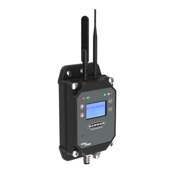
The on-board display is used to bind the radios to the wireless network while Cloud ID™ intelligence automatically detects the sensor nodes and delivers that data to Banner’s Cloud software. Software Services Authorization Card Express activation and data-driven insights. -
Page 3: Configuring The System
Bind the Sensor Nodes to the Wireless Network The Asset Monitoring Gateway with Cloud ID™ system is specially designed to offer easy binding of sensor radios to the wireless network. Banner offers an array of compatible Sensor Nodes that can measure vibration, differential pressure, temperature and humidity, tank level, and other data signals that are critical to monitor within an operation. -
Page 4: [Step Three] Connect To The Local Network
Connect to the Local Network By default, the Asset Monitoring Gateways are intended to push data to the Banner Cloud Data Services platform using a local area network. A specialized Ethernet cable is included with the Gateway to complete this connection. - Page 5 Configuring the Cellular Communication By default, the Asset Monitoring Gateway with Cloud ID™ is intended to use Ethernet communication. However, it may be preferable to use cellular communication when adding the device to a local area network is difficult, not desired, or when some applications require remote monitoring through a widely available cellular network.
-
Page 6: Activating The Services
8. Click Save. The Banner CDS application creates a storage location for the system and begins searching for a data push from the Gateway. The Asset Monitoring System is designed to push data to the Cloud at a five-minute interval with Ethernet communication or a ten-minute interval with cellular communication. -
Page 7: [Step Six] View Data And Dashboards
View Data and Dashboards After the Banner CDS application has detected the Gateway, use the navigation pane on the left side to view the Gateway. Click Details next to the Gateway Name. The device Details page provides a list of sensor objects for each Sensor Node bound to the system. -
Page 8: Compatible Sensor Nodes For Your Asset Monitoring Gateway
Compatible Sensor Nodes for Your Asset Monitoring Gateway Use the simple binding process to bind sensor nodes to a gateway, and monitor tank level, ambient temperature and humidity, and the health of rotating machines and pressurized systems. The radio frequency of compatible sensors must match the radio frequency of the gateway controller (or some other designator). - Page 9 All-in-One Temperature and Humidity Sensor Node Temperature and humidity wireless nodes monitor environmental conditions in a variety of applications, such as refrigerators or chillers, warehouses, cleanrooms, incubators, storage rooms, and distribution centers. Available accessories are shown below. Radio Frequency Power Supply Measurement Range Inputs Models...
- Page 10 Wireless Node and Pressure Sensor Wireless node and pressure transducers measure air, gas, and liquid pressure systems and equipment. Available accessories are shown below. Communication Power Supply Pressure Range Inputs Models 900 MHz ISM band DX80N9Q45UPSD-PS50 D cell lithium battery 0–50 PSI D cell lithium battery 2.4 GHz ISM band...
- Page 11 FAQ and Troubleshooting Guide A truncated list of Frequently Asked Questions (FAQ) and additional information to assist with the operation of a Banner Cloud ID(tm) System is provided below. For the complete guide, please consult the FAQ and Troubleshooting document on our website (b_51820899).
- Page 12 8. Repeat the process in this step to define each Alarm Group. Step Four: Modify the Alarms The default alarms created by the Banner Cloud ID™ systems can be modified to appropriately match the requirements of the application. Use the following steps to complete the edits needed for your deployment.
- Page 13 Warning threshold, and red to indicate a measurement has surpassed a Critical threshold. These are your ‘Check Engine Lights’ and are a visual representation of the current state of your equipment. How do I delete a Gateway from my Banner Cloud Data Services account? Follow these steps to delete a Gateway from the Cloud software: 1.
- Page 14 Banner Engineering Corp. 9714 Tenth Avenue North • Minneapolis, Minnesota 55441 763-544-3164 • 1-888-373-6767 www.bannerengineering.com 222401 Rev E © 2023 Banner Engineering Corp. Mpls. MN USA...
Need help?
Do you have a question about the Asset Monitoring Gateway and is the answer not in the manual?
Questions and answers