Table of Contents
Advertisement
Quick Links
Kichler
®
Lighting
7711 East Pleasant Valley Road
P.O. Box 318010
Cleveland, Ohio 44131-8010
Customer Service
866.558.5706
8:30 AM to 5:00 PM EST,
Monday - Friday
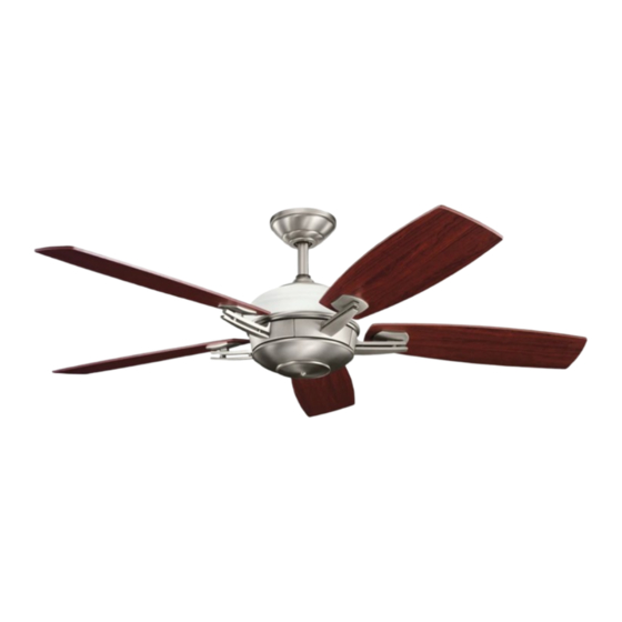
Brinbourne
Designed to coordinate with a popular Kichler Lighting collection.
Includes our
CoolTouch
Control System
TM
Looks permanent, but goes wherever you go!
U.S. Patent Pending
Instruction Manual
TM
®
™
A Kichler
Décor
ceiling fan
Advertisement
Table of Contents

Related Manuals for Kichler Lighting Brinbourne 300262


Summary of Contents for Kichler Lighting Brinbourne 300262
- Page 1 Brinbourne ® ™ A Kichler Décor ceiling fan Designed to coordinate with a popular Kichler Lighting collection. Includes our CoolTouch Control System Looks permanent, but goes wherever you go! U.S. Patent Pending Kichler ® Lighting 7711 East Pleasant Valley Road P.O.
-
Page 2: Safety Rules
1. SAFETY RULES 1. To reduce the risk of electric shock, insure 10. Do not use water or detergents when cleaning the fan or fan blades. A dry dust electricity has been turned off at the circuit breaker or fuse box before beginning. cloth or lightly dampened cloth will be suitable for most cleaning. -
Page 3: Tools And Materials Required
Brinbourne 2. TOOLS AND MATERIALS REQUIRED Philips screw driver Blade screw driver 11 mm wrench Step ladder Wire cutters 3. PACKAGE CONTENTS Unpack your fan and check the contents. You should have the following items: Fan blades (5) Canopy & Ceiling mounting bracket Ball/downrod assembly Coupling cover Glass housing... -
Page 4: Mounting Options
4. MOUNTING OPTIONS If there isn't an existing UL (cUL for Canadian Installation) listed mounting box, then read the following instructions. Disconnect the power by removing fuses or turning off circuit breakers. Secure the outlet box directly to the building structure. -
Page 5: Hanging The Fan
Brinbourne 5. HANGING THE FAN Ceiling mounting bracket REMEMBER to turn off the power before you begin. Canopy To properly install your ceiling fan, follow the steps below. Canopy cover Step 1. Remove the decorative canopy bottom Fig. 5 cover from the canopy by turning the cover counter clockwise. - Page 6 Step 8. Carefully place the glass housing onto the metal plate, slip the coupling cover, Cross pin canopy cover and canopy onto the downrod. Hanger ball Hanger ball Thread the hanger ball onto the downrod, insert the cross pin through the downrod and Downrod tighten.
-
Page 7: Installation Of Safety Support
Brinbourne 6. INSTALLATION OF SAFETY SUPPORT (required for Canadian installation ONLY) A safety support cable is provided to help prevent the ceiling fan from falling, please install it as follows. Ceiling mounting Attach bracket Step 1. Attach the provided wood screw and safety cable to ceiling joist washers to the ceiling joist next to the mounting... -
Page 8: Finishing The Installation
Connect the white wire from the fan to the white Outlet box wire marked "TO MOTOR N" from the receiver. Connect the blue wire from the fan to the blue White (neutral) wire marked "FOR BOTTOM LIGHT" from the Black (hot) receiver. -
Page 9: Attaching The Fan Blades
Brinbourne 9. ATTACHING THE FAN BLADES Step 1. Attach a blade to a blade bracket using the screws and fiber washers provided. (Fig.16) Make sure the blade is straight when set on the blade bracket. Tighten each mounting screw and then repeat this procedure for each blade. - Page 10 11. INSTALLING THE MOUNTING PLATE & DECORATIVE CAP Step 1. Loosen the two mounting screws on the inside of the bottom housing then remove and save the third screw. Step 2. Remove the plug from the mounting plate and then place the key holes on the mounting plate over the 2 screws previously loosened from the bottom housing, turn the cover until it locks in place at the narrow...
-
Page 11: Installing The Batteries
Brinbourne 13. INSTALLING THE BATTERIES Remove the battery compartment cover on the back of the CoolTouch™ Transmitter and insert both batteries provided. Make sure the + sign is facing up. Take care during this procedure NOT TO move the frequency dip switches inside this compartment. - Page 12 Speed settings for warm or cool weather depend on factors such as the room size. Ceiling height, number of fans and so on. Warm Weather Operation: Forward (counter clockwise) A downward airflow creates a cooling effect as shown in Fig. 22. This allows you to set your air conditioner on a warmer setting without affecting your general comfort.
-
Page 13: Installing The Cooltouch Control System Wall Plate
Brinbourne ™ 15. INSTALLING THE COOLTOUCH CONTROL SYSTEM WALL PLATE Outlet box Switch Select a location to install your CoolTouch™ Control System Transmitter. You can replace Wall plate an existing wall switch or, install the transmitter on ANY flat surface. Option 1: Install the control system using an existing wall switch outlet box. -
Page 14: Troubleshooting
17. TROUBLESHOOTING Problem Solution Fan will not start. 1. Check circuit fuses or breakers. 2. Check all electrical connections to insure proper contact. CAUTION: Make sure the main power is OFF when checking any electrical connection. 3. Make sure the transmitter batteries are installed properly. Positive (+) side facing out.
Need help?
Do you have a question about the Brinbourne 300262 and is the answer not in the manual?
Questions and answers