
Related Manuals for Kichler Lighting 300457


Summary of Contents for Kichler Lighting 300457
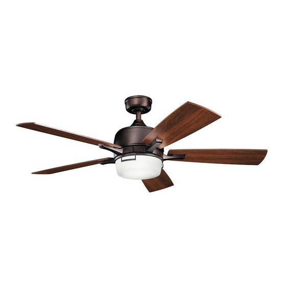
- Page 1 52" LEEDS LED FAN Product images may vary slightly from actual product. INSTRUCTION MANUAL...
-
Page 3: Table Of Contents
TABLE OF CONTENTS INSTALLING THE LED LIGHT KIT SAFETY RULES................4 AND GLASS SHADE..............15 TOOLS REQUIRED..............INSTALLING THE BATTERIES..........PACKAGE CONTENTS............. OPERATING INSTRUCTIONS..........MOUNTING OPTIONS............. INSTALLING THE WALL CONTROL HANGING THE FAN..............SYSTEM WALL PLATE............INSTALLATION OF SAFETY SUPPORT......OPERATION INSTRUCTIONS..........ELECTRICAL CONNECTIONS.......... -
Page 4: Safety Rules
SAFETY RULES 1. To reduce the risk of electric shock, insure electricity has been 8. Avoid placing objects in the path of the blades. turned off at the circuit breaker or fuse box before beginning. 9. To avoid personal injury or damage to the fan and other items, be cautious when working around or cleaning the fan. -
Page 5: Tools Required
TOOLS REQUIRED PACKAGE CONTENTS Philips screw driver Unpack your fan and check the Blade screw driver contents. You should have the following items: 11 mm wrench Step ladder a. Fan blades (5) Wire cutters b. Canopy & Ceiling mounting bracket c. -
Page 6: Mounting Options
MOUNTING OPTIONS If there isn't an existing UL (cUL for Canadian Installation) listed mounting box, then read the following instructions. Disconnect the power by removing fuses or turning off circuit breakers. Secure the outlet box directly to the building structure. Use appropriate fasteners and building materials. -
Page 7: Hanging The Fan
HANGING THE FAN REMEMBER to turn off the power before you begin. Hanger bracket To properly install your ceiling fan, follow the steps below. Step 1. Remove the decorative canopy bottom cover from the canopy by turning the cover counter clockwise. (Fig. 5) Ceiling canopy Step 2. - Page 8 HANGING THE FAN (continued) Cross pin Step 5. Remove the hanger ball from the downrod assembly by loosening the set screw, unscrewing and removing removing the cross Hanger pin and unscrewing the ball off the rod. (Fig. 7) ball Set screw Step 6.
- Page 9 HANGING THE FAN (continued) Step 8. Slip the coupling cover , canopy cover and canopy onto the Downrod downrod. (Fig. 9) Canopy Thread the hanger ball onto the downrod, insert the cross pin through the downrod and tighten. Now tighten the set screw. (Fig. 9) Canopy cover Step 9.
-
Page 10: Installation Of Safety Support
INSTALLATION OF SAFETY SUPPORT (required for Canadian installation ONLY) A safety support cable is provided to help prevent the ceiling fan from falling. Step 1. Attach the provided wood screw and washers to the ceiling joist Ceiling mounting next to the mounting bracket but do not tighten. (Fig. 11) bracket Attach safety cable... -
Page 11: Electrical Connections
ELECTRICAL CONNECTIONS Code switch WARNING: To avoid possible electrical shock, be sure you have turned off the power at the main circuit panel. ON ECE LIGHT 1 2 3 4 Follow the steps below to connect the fan to your household wiring. ON ECE FAN OFF Use the wire connecting nuts suppled with your fan. - Page 12 ELECTRICAL CONNECTIONS (continued) Outlet box Step 2. Motor to Receiver Electrical Connections: (Fig. 14) Connect the White (neutral) Black (hot) black wire from the fan to the black wire marked "TO MOTOR L" on Green or bare copper (ground) the receiver. Connect the white wire from the fan to the white wire Black ("AC IN L") marked "TO MOTOR N"...
-
Page 13: Finishing The Installation
FINISHING THE INSTALLATION Step 1. Tuck all the connections neatly into the ceiling outlet box. Outlet box Step 2. Slide the canopy up to the mounting bracket and place one of the key hole slots over the mounting screw on the mounting bracket. Rotate the canopy until the screw head locks in place at the narrow Ceiling mounting... -
Page 14: Attaching The Fan Blades
ATTACHING THE FAN BLADES Step 1. Attach a blade to a blade bracket using the screws and fiber washers provided. (Fig. 16) Make sure the blade is straight when set on the blade bracket. Tighten each mounting screw and then repeat this procedure for Screws each blade. -
Page 15: Installing The Led Light Kit And Glass Shade
INSTALLING THE LED LIGHT KIT AND GLASS SHADE NOTE: Before starting installation, disconnect the power by turning off the circuit breaker or removing the fuse at fuse box. Step 1. Loosen the three mounting screws on the inside of the LED light kit. -
Page 16: Installing The Batteries
INSTALLING THE BATTERIES Remove the face plate of the Wall Switch by lifting at the top and then insert the supplied 12V battery. Duracell MN21/Eveready LIGHT A23/GP 23A all 12V. Replace the switch face plate. ON ECE FAN OFF 1 2 3 4 To prevent possible damage to the transmitter, remove these batteries if not used for long periods of time (months). -
Page 17: System Wall Plate
INSTALLING THE BASIC FUNCTION Outlet box WALL CONTROL SYSTEM WALL Switch Wall plate PLATE Select a location to install the Basic Function Wall Control System Transmitter and Wall Plate. Install the wall plate using an existing wall switch outlet box. Make sure the electrical power is TURNED OFF at the main panel before continuing. -
Page 18: Operation Instructions
OPERATING INSTRUCTIONS NOTE: This control system is NOT designed to "Reverse" the rotation of the blades. To set the fan blades in reverse, the reverse slide switch is located on the top of the motor housing. Warm weather - Forward (counter clockwise) A downward airflow creates a cooling effect as shown in Fig. -
Page 19: Troubleshooting
TROUBLESHOOTING Problem Solution Fan will not start. 1. Check circuit fuses or breakers. 2. Check all electrical connections to insure proper contact. CAUTION: Make sure the main power is OFF when checking any electrical connection. Fan sounds noisy. 1. Make sure all motor housing screws are snug. 2. - Page 20 www.kichler.com KICHLER® LIGHTING 7711 EAST PLEASANT VALLEY ROAD P.O. BOX 318010 CLEVELAND, OHIO 44131-8010 CUSTOMER SERVICE 866.558.5706 8:30 AM TO 5:00 PM EST, MONDAY - FRIDAY...
Need help?
Do you have a question about the 300457 and is the answer not in the manual?
Questions and answers