
Subscribe to Our Youtube Channel
Related Manuals for Kichler Lighting Imari 65


Summary of Contents for Kichler Lighting Imari 65
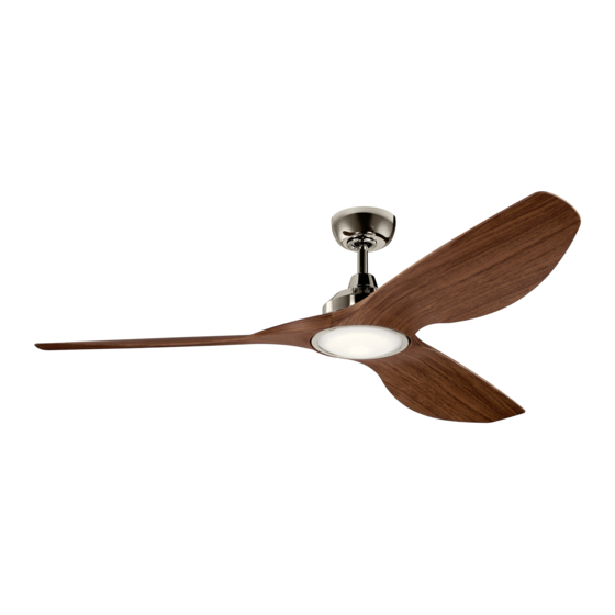
- Page 1 65" Imari Product images may vary slightly from actual product. INSTRUCTION MANUAL Model#: 300365 READ AND SAVE THESE INSTRUCTIONS...
-
Page 2: Table Of Contents
TABLE OF CONTENTS SAFETY RULES ..............3 INSTALLING THE LED LIGHT KIT AND DECORATIVE RING ........14 TOOLS REQUIRED ............4 CONTROL SYSTEM SET-UP ........15 PACKAGE CONTENTS ............4 BUTTON INSTRUCTION ..........16 MOUNTING OPTIONS .............5 SENSORLESS DC CONTROL HANGING THE FAN ............6 PAIRING PROCEDURES ..........17 INSTALLATION OF SAFETY CABLE ...... -
Page 3: Safety Rules
SAFETY RULES 1. CAUTION – RISK OF SHOCK – Disconnect Power at the main 9. Avoid placing objects in the path of the blades. circuit breaker panel or main fusebox before starting and during the installation. 10. WARNING: make sure the power is disconnected before cleaning your fan. -
Page 4: Tools Required
TOOLS REQUIRED • Phillips Screwdriver • Blade Screwdriver • 11 mm Wrench • Step Ladder • Wire Cutters PACKAGE CONTENTS Unpack your fan and check the contents . You should have the following items: A. Fan Blades (3) H. Decorative Ring B. -
Page 5: Mounting Options
MOUNTING OPTIONS If there isn’t an existing UL (cUL for Canadian Installation) listed mounting box, then read the following instructions. Disconnect the power by removing fuses or turning off circuit breakers. Outlet box Secure the outlet box directly to the building structure. Use appropriate fasteners and building materials. -
Page 6: Hanging The Fan
HANGING THE FAN REMEMBER to turn off the power before you begin. Hanger Bracket To properly install your ceiling fan, follow the steps below. Step 1. Remove the decorative canopy bottom cover from the canopy by Ceiling turning the cover counter clockwise. (Fig. 5) Canopy Step 2. - Page 7 HANGING THE FAN (continued) Cross Pin WARNING: All set screws must be checked, and retightened where Hanger necessary, before installation. Ball Set Screw Step 5. Remove the hanger ball from the downrod assembly by loosening the set screw, unscrewing and removing the cross pin and unscrewing the Download ball off the rod.
- Page 8 HANGING THE FAN (continued) Step 8. Slip the coupling cover, secure ring , canopy cover and canopy Downrod onto the downrod. (Fig. 9) Canopy Thread the hanger ball onto the downrod, insert the cross pin through the downrod and tighten. Now tighten the set screw. (Fig. 9) Canopy Cover Step 9.
-
Page 9: Installation Of Safety Cable
INSTALLATION OF SAFETY CABLE (required for Canadian installation ONLY) A safety support cable is provided to help prevent the ceiling fan from falling, please install it as follows. Ceiling mounting Step 1. Attach the wood screw and washers to the ceiling joist next to the bracket Attach safety cable to ceiling joist with... -
Page 10: Electrical Connections
ELECTRICAL CONNECTIONS WARNING: Carefully read and retain this Instruction Manual A. CEILING FAN TO RECEIVER WIRE CONNECTION for future reference. Step 1. Connect the Blue wire from the fan (motor) to the Blue wire from the receiver. White wire from the fan (motor) to the WARNING: To avoid possible electrical shock, be sure the White wire from the receiver. - Page 11 GROUND BLACK WHITE CONDUCTOR YELLOW GRAY WHITE BLUE BLACK Outlet BLACK Receiver BLACK BLACK BLACK BLACK GREEN YELLOW/GREEN GROUND WHITE Wall Outlet Box BLACK 2P Plug Filter Fig. 13 65" Imari | 11...
-
Page 12: Finishing The Installation
FINISHING THE INSTALLATION Step 1. Tuck all the connections neatly into the ceiling outlet box. Outlet Box Step 2. Slide the canopy up to the mounting bracket and place one of the key hole slots over the mounting screw on the mounting bracket. Rotate Ceiling the canopy until the screw head locks in place at the narrow section of Mounting... -
Page 13: Attaching The Fan Blades
ATTACHING THE FAN BLADES CAUTION: To reduce the risk of electric shock, disconnect the electrical supply circuit to the fan before installing fan blades. Step 1. Align the holes from the blade to the holes from the motor, and secure the blade in place with screws and flat washers provided. (Fig. 15) Step 2. -
Page 14: Installing The Led Light Kit And Decorative Ring
INSTALLING THE LED LIGHT KIT AND DECORATIVE RING CAUTION: To reduce the risk of electric shock, disconnect the electrical supply circuit to the fan before installing light kit. Step 1. Remove the two mounting screws on the inside of the LED light kit. -
Page 15: Control System Set-Up
CONTROL SYSTEM SET-UP IMPORTANT: Ceiling fan blades MUST be installed before pairing procedure can begin. Green Light Program the wall control and/or the handset control separately. Once the following pairing is successfully done, both the wall control and the handset control can be used for the fan. For/Rev Switch Press the power button on wall control to TURN THE POWER ON. -
Page 16: Button Instruction
BUTTON INSTRUCTION LED Indicator Red LED: Transmitter signal indicator. When RF signal is sending, the red light will illuminate. Green LED: To show the Forward and Reverse indicator. ON/OFF Button ON: Turn on the power. OFF: Turn off the power. Reverse Button When the fan is running, press and release the Reverse button one time, the fan will change operating direction. -
Page 17: Sensorless Dc Control Pairing Procedures
SENSORLESS DC CONTROL PAIRING PROCEDURES IMPORTANT: Ceiling fan blades MUST be installed before pairing procedure can begin. Step 1. Program the wall control and/or the handset control separately. Once the following pairing is successfully done, both the wall control and the handset control can be used for the fan. For wall control, press the “... -
Page 18: Installing The Wall Control System Wall Plate
INSTALLING THE WALL CONTROL SYSTEM WALL PLATE CAUTION: MAKE SURE THE ELECTRICITY IS TURNED OFF AT THE MAIN JUNCTION BOX OR THE CORRECT FUSE HAS BEEN PULLED Outlet Box OFF AT THE MAIN JUNCTION BOX BEFORE CONTINUING. Switch Wall Plate WARNING: All wiring must be in accordance with the National Electrical Screws Code local electrical codes. -
Page 19: Operating Instructions
OPERATING INSTRUCTIONS To operate the reverse function on this fan, press the “Reverse” button while fan is running. Speed setting for warm or cool weather depends on factors such as the room size, ceiling height, number of fans and so on. Warm weather - Forward (counter clockwise) A downward airflow creates a cooling effect as shown in Fig. -
Page 20: Troubleshooting
TROUBLESHOOTING Problem Solution Fan will not start. 1. Check circuit fuses or breakers. 2. Check all electrical connections to ensure proper contact. CAUTION: Make sure the main power is OFF when checking any electrical connection. Fan sounds noisy. 1. Make sure all motor housing screws are snug. 2. - Page 21 TROUBLESHOOTING Problem Solution Fan wobble. 1. Check that all blade and blade arm screws are secure. 2. Most fan wobbling problems are caused when blade levels are unequal. Check this level by selecting a point on the ceiling above the tip of one of the blades. Measure this distance. Rotate the fan until the next blade is positioned for measurement.
-
Page 22: Fcc Information
FCC INFORMATION This device complies with part 15 of the FCC Rules. Operation is subject to the following two conditions: 1) This device may not cause harmful interference, and 2) This device must accept any interference received, including interference that may cause undesired operation. Note: This equipment has been tested and found to comply with the limits for a Class B digital device, pursuant to part 15 of the FCC Rules. - Page 23 KICHLER LIGHTING LLC 30455 SOLON ROAD SOLON, OHIO 44139 CUSTOMER SERVICE 866.558.5706 8:00 AM TO 5:00 PM EST, MONDAY - FRIDAY 2022/06/13 © Kichler Lighting LLC. All Rights Reserved.
- Page 24 65 po Imari Les images du produit peuvent varier légèrement par rapport au produit réel. MANUEL D’INSTRUCTIONS Modèle nº : 300365 LISEZ ET CONSERVEZ CES INSTRUCTIONS...
- Page 25 TABLE DES MATIÈRES RÈGLES DE SÉCURITÉ ..........3 INSTALLATION DE L’ENSEMBLE D’ÉCLAIRAGE À DEL ET DE LA OUTILS NÉCESSAIRES ..........4 BAGUE DÉCORATIVE ..........14 CONTENU DU COLIS ..........4 CONFIGURATION DU SYSTÈME DE COMMANDE ............15 OPTIONS DE MONTAGE ...........5 INSTRUCTION SUR LES BOUTONS ....16 SUSPENDRE LE VENTILATEUR ......6 PROCÉDURES D’APPARIEMENT DE INSTALLATION DU CÂBLE DE SÉCURITÉ...
-
Page 26: Règles De Sécurité
RÈGLES DE SÉCURITÉ 1. ATTENTION : RISQUE DE CHOC : Débranchez l’alimentation au 9. Évitez de placer des objets sur la trajectoire des pales. panneau du disjoncteur principal ou à la boîte à fusibles principale 10. AVERTISSEMENT : assurez-vous que l’alimentation est coupée avant de démarrer et pendant l’installation. -
Page 27: Outils Nécessaires
OUTILS NÉCESSAIRES • Tournevis cruciforme • Tournevis à lame • Clé de 11 mm • Escabeau • Pinces coupantes CONTENU DU COLIS Déballez votre ventilateur et vérifiez le contenu. Vous devriez avoir les éléments suivants : A. Pales de ventilateur (3) H. -
Page 28: Options De Montage
OPTIONS DE MONTAGE S’il n’y a pas de boîtier de montage homologué UL (cUL pour installation canadienne), lisez les instructions suivantes. Débranchez l’alimentation en retirant les fusibles ou en désactivant les disjoncteurs. Boîtier de sortie Fixez le boîtier de sortie directement à la structure du bâtiment. -
Page 29: Suspendre Le Ventilateur
SUSPENDRE LE VENTILATEUR RAPPELEZ-VOUS de couper l’alimentation avant de commencer l’installation. Support de suspension Pour installer correctement votre ventilateur de plafond, suivez les étapes ci-dessous. Auvent de Étape 1. Retirez le couvercle inférieur décoratif de l’auvent en le tournant plafond dans le sens inverse des aiguilles d’une montre. - Page 30 SUSPENDRE LE VENTILATEUR (suite) Broche croisée AVERTISSEMENT : Toutes les vis de réglage doivent être vérifiées et Boule de resserrées si nécessaire avant l’installation. suspension Vis de réglage Étape 5. Retirez la boule de suspension de l’assemblage de la tige descendante en desserrant les vis de réglage, en dévissant et retirant la Télécharger goupille transversale et en dévissant la boule hors de la tige.
- Page 31 SUSPENDRE LE VENTILATEUR (Suite) Étape 8. Glissez le couvercle du couplage, la bague de sécurité, le cache de Tige descendante l’auvent et l’auvent sur la tige descendante. (Fig. 9) Auvent Enfilez la boule de suspension sur la tige descendante, insérez la tige transversale à...
-
Page 32: Installation Du Câble De Sécurité
INSTALLATION DU CÂBLE DE SÉCURITÉ (requis pour l’installation au Canada SEULEMENT) Un câble de support de sécurité est fourni pour aider à empêcher le ventilateur de plafond de tomber, veuillez l’installer comme suit. Support de montage Étape 1. Fixez la vis à bois et les rondelles à la solive de plafond à côté du support au plafond Fixez le câble de sécurité... -
Page 33: Raccordements Électriques
RACCORDEMENTS ÉLECTRIQUES AVERTISSEMENT : Lisez attentivement et conservez ce A. CONNEXION DES FILS DU VENTILATEUR DE PLAFOND manuel d’instructions pour toute référence ultérieure. AU RÉCEPTEUR Étape 1. Raccordez le fil bleu du ventilateur (moteur) au fil bleu du AVERTISSEMENT : Pour éviter tout risque d’électrocution, récepteur;... - Page 34 CONDUCTEUR NOIR BLANC DE TERRE JAUNE GRIS ROUGE BLANC BLEU NOIR Boîtier de sortie NOIR Récepteur NOIR NOIR NOIR NOIR VERT FIL DE TERRE JAUNE/VERT BLANC Boîte de sortie murale NOIR Fiche 2P Filtre Fig. 13 65 po Imari | 11...
-
Page 35: Fin De L'installation
FIN DE L’INSTALLATION Étape 1. Rentrez soigneusement toutes les connexions dans la boîte de sortie au plafond. Boîtier de sortie Étape 2. Faites glisser l’auvent jusqu’au support de montage et placez Support de l’une des fentes du trou de serrure sur la vis de montage du support de montage au plafond montage. -
Page 36: Fixation Des Pales Du Ventilateur
FIXATION DES PALES DU VENTILATEUR ATTENTION : Pour réduire le risque d’électrocution, débranchez le circuit d’alimentation électrique du ventilateur avant d’installer les pales du ventilateur. Étape 1. Alignez les trous de la pale sur les trous du moteur, et fixez la pale en place avec les vis et les rondelles plates fournies. -
Page 37: Installation De L'ensemble D'éclairage À Del Et De La Bague Décorative
INSTALLATION DE L’ENSEMBLE D’ÉCLAIRAGE À DEL ET DE LA BAGUE DÉCORATIVE ATTENTION : Pour réduire le risque d’électrocution, débranchez le circuit d’alimentation électrique du ventilateur avant d’installer la trousse d’éclairage. Connecteurs de fil Étape 1. Retirez les deux vis de montage situées à l’intérieur l’ensemble Plaque d’éclairage d’éclairage à... -
Page 38: Configuration Du Système De Commande
CONFIGURATION DU SYSTÈME DE COMMANDE IMPORTANT : Les pales du ventilateur de plafond DOIVENT être Feu vert installées avant que la procédure d’appariement puisse commencer. Programmez séparément la commande murale et/ou la télécommande. Une fois l’appariement suivant effectué avec succès, la commande murale Interrupteur de commande et la télécommande peuvent toutes deux être utilisées pour le ventilateur. -
Page 39: Instruction Sur Les Boutons
INSTRUCTION SUR LES BOUTONS Témoin DEL DEL rouge : Indicateur de signal de l’émetteur. Lorsque le signal RF est envoyé, le voyant rouge s’allume. DEL verte : Pour afficher l’indicateur de marche avant et arrière. Bouton « MARCHE/ARRÊT » MARCHE : Mettez le courant. ARRÊT : Coupez le courant. -
Page 40: Procédures D'appariement De La Commande Cc Sans Capteur
PROCÉDURES D’APPARIEMENT DE LA COMMANDE CC SANS CAPTEUR IMPORTANT : Les pales du ventilateur de plafond DOIVENT être installées avant que la procédure d’appariement puisse commencer. Étape 1. Programmez séparément la commande murale et/ou la télécommande. Une fois l’appariement suivant effectué avec succès, la commande murale et la télécommande peuvent toutes deux être utilisées pour le ventilateur. -
Page 41: Installation De La Plaque Murale Du Système De Commande
INSTALLATION DE LA PLAQUE MURALE DU SYSTÈME DE COMMANDE ATTENTION : ASSUREZ-VOUS QUE L’ÉLECTRICITÉ EST COUPÉE AU NIVEAU DE LA BOÎTE DE RACCORDEMENT PRINCIPALE OU QUE LE FUSIBLE CORRECT A ÉTÉ RETIRÉ AU NIVEAU DE LA BOÎTE DE Boîtier de sortie RACCORDEMENT PRINCIPALE AVANT DE CONTINUER. -
Page 42: Instructions D'utilisation
INSTRUCTIONS D’UTILISATION Pour activer la fonction d’inversion sur ce ventilateur, appuyez sur le bouton « Inversion » pendant que le ventilateur fonctionne. Le réglage de la vitesse par temps chaud ou frais dépend de facteurs tels que la taille de la pièce, la hauteur du plafond, le nombre de ventilateurs, etc. Par temps chaud –... -
Page 43: Dépannage
DÉPANNAGE Problème Solution Le ventilateur ne 1. Vérifiez les fusibles ou les disjoncteurs. démarre pas. 2. Vérifiez tous les raccordements électriques pour assurer un bon contact. ATTENTION : Assurez-vous que l’alimentation principale est coupée lors de la vérification de tout raccordement électrique. Le ventilateur fait 1. - Page 44 DÉPANNAGE Problème Solution Le ventilateur vacille. 1. Vérifiez que toutes les vis de la pale et du bras de pale sont bien fixées. 2. La plupart des problèmes d’oscillation du ventilateur sont causés lorsque les niveaux des pales sont inégaux. Vérifiez ce niveau en sélectionnant un point sur le plafond au-dessus de la pointe de l’une des pales.
-
Page 45: Informations Fcc
INFORMATIONS FCC Cet appareil est conforme aux exigences de la section 15 du règlement de la FCC. Fonctionnement assujetti aux deux (2) conditions d’utilisation suivantes : 1) Cet appareil ne doit pas provoquer d’interférences nuisibles, et 2) Cet appareil doit accepter tous les brouillages reçus, y compris ceux pouvant causer un fonctionnement indésirable. Remarque : Cet équipement a été... - Page 46 KICHLER LIGHTING LLC 30455 SOLON ROAD SOLON, OHIO 44139 SERVICE À LA CLIENTÈLE 866.558.5706 8 h à 17 h EST, DU LUNDI AU VENDREDI 2022/06/13 © Kichler Lighting LLC. Tous droits réservés.
- Page 47 Imari de 65" Las imágenes del producto pueden diferir ligeramente del producto real. MANUAL DE INSTRUCCIONES Modelo n.°: 300365 LEER Y GUARDAR ESTAS INSTRUCCIONES...
- Page 48 ÍNDICE NORMAS DE SEGURIDAD........3 INSTALACIÓN DEL KIT DE LUCES LED Y EL ANILLO DECORATIVO ........14 HERRAMIENTAS NECESARIAS ......4 CONFIGURACIÓN DEL SISTEMA CONTENIDO DEL PAQUETE........4 DE CONTROL ............15 OPCIONES DE MONTAJE .........5 INSTRUCCIONES DE LOS BOTONES ....16 COLGAR EL VENTILADOR ........6 PROCEDIMIENTOS DE EMPAREJAMIENTO DEL CONTROL DE CD SIN SENSOR ....
-
Page 49: Normas De Seguridad
NORMAS DE SEGURIDAD 1. PRECAUCIÓN: RIESGO DE DESCARGA ELÉCTRICA. Desconecte 9. Evite colocar objetos en el camino de las aspas. la energía en el panel del disyuntor principal o en la caja de fusibles 10. ADVERTENCIA: asegúrese de que la corriente esté desconectada principal antes de comenzar y durante la instalación. -
Page 50: Herramientas Necesarias
HERRAMIENTAS NECESARIAS • Destornillador Phillips • Destornillador plano • Llave de 11 mm • Escalera de mano • Cortadores de alambre CONTENIDO DEL PAQUETE Desempaque su ventilador y verifique el contenido. Debería tener los siguientes elementos: A. Aspas del ventilador (3) G. -
Page 51: Opciones De Montaje
OPCIONES DE MONTAJE Si no existe una caja de montaje con certificación UL (cUL para la instalación canadiense), lea las siguientes instrucciones. Desconecte la corriente quitando los fusibles o apagando los disyuntores. Caja de salida Fije la caja de salida directamente a la estructura del edificio. Utilice sujetadores y materiales de construcción adecuados. -
Page 52: Colgar El Ventilador
COLGAR EL VENTILADOR RECUERDE desconectar la corriente antes de comenzar la instalación. Soporte para colgar Para instalar correctamente su ventilador de techo, siga los pasos a continuación. Paso 1. Retire la cubierta inferior decorativa del dosel girando la cubierta en Dosel sentido contrario a las agujas del reloj. - Page 53 COLGAR EL VENTILADOR (continuación) Pasador cruzado ADVERTENCIA: Todos los tornillos de fijación deben revisarse y volverse a Bola de apretar cuando sea necesario antes de la instalación. suspensión Tornillo de fijación Paso 5. Retire la bola de suspensión del conjunto de la varilla de extensión aflojando el tornillo de fijación, desatornillando y quitando el pasador Descargar transversal y desatornillando la bola para quitarla de la varilla.
- Page 54 COLGAR EL VENTILADOR (continuación) Paso 8. Deslice la cubierta del acoplamiento, conecte el anillo, la cubierta del Varilla de extensión dosel y el dosel con la varilla de extensión. (Figura 9) Dosel Enrosque la bola de suspensión en la varilla de extensión, inserte el pasador transversal a través la varilla de extensión y apriete.
-
Page 55: Instalación Del Cable De Seguridad
INSTALACIÓN DEL CABLE DE SEGURIDAD (requerido para instalación canadiense ÚNICAMENTE) Se proporciona un cable de soporte de seguridad para ayudar a evitar que el Soporte de ventilador de techo se caiga; instálelo de la siguiente manera. montaje Fije el cable de seguridad del techo a la viga del techo con tornillo y arandela... -
Page 56: Conexiones Eléctricas
CONEXIONES ELÉCTRICAS ADVERTENCIA: Lea atentamente y conserve este Manual de A. CONEXIÓN DEL VENTILADOR DE TECHO AL CABLE instrucciones para referencia futura. RECEPTOR Paso 1. Conecte el cable azul del ventilador (motor) al cable azul ADVERTENCIA: Para evitar posibles descargas eléctricas, del receptor. - Page 57 CONDUCTOR NEGROBLANCO DE TIERRA AMARILLO GRIS ROJO BLANCO AZUL NEGRO Caja de salida NEGRO Receptor NEGRO NEGRO NEGRO NEGRO VERDE A TIERRA AMARILLO/VERDE BLANCO Caja de salida NEGRO de pared Enchufe 2P Filtro Figura 13 Imari de 65" | 11...
-
Page 58: Finalización De La Instalación
FINALIZACIÓN DE LA INSTALACIÓN Paso 1. Meta todas las conexiones cuidadosamente en la caja de salida del techo. Caja de salida Paso 2. Deslice el dosel hacia arriba hasta el soporte de montaje y coloque Soporte de una de las ranuras del orificio de la llave sobre el tornillo del soporte de montaje del techo montaje. -
Page 59: Colocación De Las Aspas Del Ventilador
COLOCACIÓN DE LAS ASPAS DEL VENTILADOR PRECAUCIÓN: Para reducir el riesgo de descarga eléctrica, desconecte el circuito de suministro eléctrico al ventilador antes de instalar las aspas. Paso 1. Alinee los orificios del aspa con los orificios del motor y fije el Aspas aspa en su lugar con los tornillos y las arandelas planas proporcionados. -
Page 60: Y El Anillo Decorativo
INSTALACIÓN DEL KIT DE LUZ LED Y EL ANILLO DECORATIVO PRECAUCIÓN: Para reducir el riesgo de descarga eléctrica, desconecte el circuito de suministro eléctrico al ventilador antes de instalar el kit de luz. Paso 1. Retire los dos tornillos de montaje en el interior del kit de luz LED. Conectores de cables (Figura 17) Placa de luz... -
Page 61: Configuración Del Sistema De Control
CONFIGURACIÓN DEL SISTEMA DE CONTROL IMPORTANTE: Las aspas del ventilador de techo DEBEN instalarse Luz verde antes de que pueda comenzar el procedimiento de emparejamiento. Programe el control de pared y/o el control remoto por separado. Una vez que se haya realizado correctamente el siguiente emparejamiento, tanto Interruptor de avance/retroceso el control de pared como el control remoto pueden utilizarse para manejar el ventilador. -
Page 62: Instrucciones De Los Botones
INSTRUCCIONES DE LOS BOTONES Luz indicadora LED Luz roja LED: Indicadora de la señal del transmisor. Cuando se envía la señal de radiofrecuencia, la luz roja se ilumina. Luz verde LED: Para mostrar el indicador de avance y retroceso. Botón de ENCENDIDO/APAGADO ENCENDIDO: Enciende la corriente. -
Page 63: Procedimientos De Emparejamiento Del Control De Cd Sin Sensor
PROCEDIMIENTOS DE EMPAREJAMIENTO DEL CONTROL DE CD SIN SENSOR IMPORTANTE: Las aspas del ventilador de techo DEBEN instalarse antes de que pueda comenzar el procedimiento de emparejamiento. Paso 1. Programe el control de pared y/o el control remoto por separado. Una vez que se haya realizado correctamente el siguiente emparejamiento, tanto el control de pared como el control remoto pueden utilizarse para manejar el ventilador. -
Page 64: Instalación De La Placa De Pared Del Sistema De Control De Pared
INSTALACIÓN DE LA PLACA DE PARED DEL SISTEMA DE CONTROL DE PARED PRECAUCIÓN: ASEGÚRESE DE QUE LA ELECTRICIDAD ESTÉ APAGADA EN LA CAJA DE CONEXIONES PRINCIPAL O QUE SE HAYA APAGADO EL Caja de salida FUSIBLE CORRECTO EN LA CAJA DE CONEXIONES PRINCIPAL ANTES Interruptor DE CONTINUAR. -
Page 65: Instrucciones De Funcionamiento
INSTRUCCIONES DE FUNCIONAMIENTO Para operar la función de retroceso en este ventilador, presione el botón “Retroceso” mientras el ventilador está funcionando. El ajuste de velocidad para climas cálidos o fríos depende de factores como el tamaño de la habitación, la altura del techo, la cantidad de ventiladores, etc. Clima cálido: avance (sentido contrario a las agujas del reloj) Un flujo de aire hacia abajo crea un efecto refrescante como se muestra en la Figura 22. -
Page 66: Resolución De Problemas
RESOLUCIÓN DE PROBLEMAS Problema Solución El ventilador 1. Verifique los fusibles o disyuntores del circuito. no arranca. 2. Verifique todas las conexiones eléctricas para asegurar un contacto adecuado. PRECAUCIÓN: Asegúrese de que la corriente principal esté APAGADA cuando verifique cualquier conexión eléctrica. El ventilador 1. - Page 67 RESOLUCIÓN DE PROBLEMAS Problema Solución Oscilación del 1. Verifique que todos los tornillos de aspa y del brazo de aspa estén firmes. ventilador. 2. La mayoría de los problemas de oscilación del ventilador se deben a que los niveles de las aspas no son iguales.
-
Page 68: Información De La Fcc
INFORMACIÓN DE LA FCC Este dispositivo cumple con la parte 15 de las normas de la Comisión Federal de Comunicaciones (Federal Communications Commission, FCC). El funcionamiento está sujeto a las siguientes dos condiciones: 1) Este dispositivo no puede causar interferencias perjudiciales, y 2) Este dispositivo debe aceptar cualquier interferencia recibida, incluidas interferencias que puedan causar un funcionamiento no deseado. - Page 69 KICHLER LIGHTING LLC 30455 SOLON ROAD SOLON, OHIO 44139 SERVICIO AL CLIENTE 866.558.5706 8:00 A. M. A 5:00 P. M. EST, DE LUNES A VIERNES 13/06/2022 © Kichler Lighting LLC. Todos los derechos reservados.
Need help?
Do you have a question about the Imari 65 and is the answer not in the manual?
Questions and answers