Advertisement
Quick Links
TYGER LanderX
BEFORE INSTALLATION
READ INSTRUCTIONS CAREFULLY BEFORE STARTING
INSTALLATION. REMOVE CONTENTS FROM BOX AND
VERIFY ALL PARTS ARE PRESENT. FAILURE TO IDENTIFY
DAMAGE BEFORE INSTALLATION COULD LEAD TO A
REJECTION OF ANY CLAIM. IF MISSING PARTS OR ANY
DAMAGE FOUND, PLEASE TAKE A PICTURE FOR THE
CLAIM PURPOSE. TO FILE YOUR CLAIM, PLEASE VISIT:
WWW.TYGERAUTO.COM/CONTACT
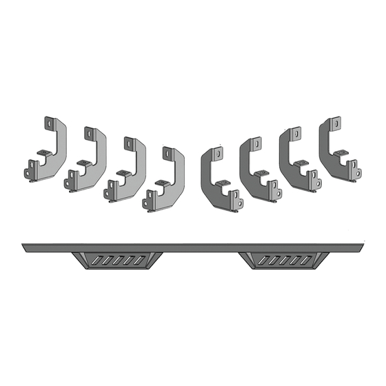
x1
Driver/Left TYGER LanderX
x1
Passenger/Right TYGER LanderX
x4
Driver/Left Mounting Bracket
Reference the letters printed on the brackets to determine mounting locations
A
Customer Support: www.tygerauto.com/contact
x4
Passenger/Right Mounting Brackets
x16
8-1.25mm x 25mm Combination Hex Bolts
x16
8-1.25mm x 30mm Hex Bolt
A
A
Driver/Left TYGER LanderX
B
B
Passenger/Right TYGER LanderX
TORQUE VALUES
Fastener Size
Class 8.8 Torque (ft-lbs)
6mm
8mm
15-16
10mm
31-32
12mm
54-55
14mm
87-88
x16
8mm x 24mm x 2mm Flat Washers
B
x16
8mm Lock Washers
A
B
1/5
TG-LX3C82458
Class 10.9 Torque (ft-lbs)
6-7
22-23
44-45
78-79
125-126
A
6-7
B
V230802
Advertisement

Related Manuals for Tyger LanderX


Summary of Contents for Tyger LanderX
- Page 1 78-79 CLAIM PURPOSE. TO FILE YOUR CLAIM, PLEASE VISIT: 14mm 87-88 125-126 WWW.TYGERAUTO.COM/CONTACT Driver/Left TYGER LanderX Passenger/Right Mounting Brackets 8mm x 24mm x 2mm Flat Washers Passenger/Right TYGER LanderX 8-1.25mm x 25mm Combination Hex Bolts 8mm Lock Washers 8-1.25mm x 30mm Hex Bolt...
-
Page 2: Bottom View
TYGER LanderX Bottom View ATTENTION: Refer to the D or P labelling on the tubes to determine the Driver or Passenger side steps. XX-D Front Driver/Left LanderX XX-P Front Passenger/Right LanderX PROCEDURE: REMOVE CONTENTS FROM BOX. VERIFY ALL PARTS ARE PRESENT. - Page 3 TYGER LanderX STEP 4 Continue to the third mounting location next along the body panel (Fig 6). Repeat STEPS 1 & 2 to attach (1) Driver/Left Side Mounting Bracket to the third mounting location (Fig 7). Driver/Left side Installation Pictured...
- Page 4 (front to back or rotate), the TYGER LanderX against the Brackets or damage to the finish may result. Attach the TYGER LanderX to the Brackets with (8) 8mm x 25mm Combo Hex Bolt assemblies (Fig 9-14). DO NOT fully tighten hardware.
- Page 5 (Fig 13) Driver/Left TYGER LanderX attached to Third Mounting Bracket (Fig 14) Driver/Left TYGER LanderX attached to rear Mounting Bracket STEP 7 Level and adjust the TYGER LanderX and tighten all hardware. Driver/Left side Installation Pictured Complete Installation...
Need help?
Do you have a question about the LanderX and is the answer not in the manual?
Questions and answers