
Related Manuals for Elektro-Automatik PS 800 R Series


Summary of Contents for Elektro-Automatik PS 800 R Series
- Page 1 Netzgeräte-Serie Power Supply Series PS 800 R 5000W EA-PS 880-170R : 21 540 122 EA-PS 8200-70R : 21 540 124 EA-PS 8500-30R : 21 540 123...
- Page 3 (Abdeckung montieren, da das Gerät gefähr- liche Ausgangsspannungen erzeugen kann. • Alterung des Gerätes und sehr häufige Benutzung kann bei Bedienelementen (Taster, Trimmer) dazu führen, daß diese nicht mehr wie erwartet reagieren. © 2010, Elektro-Automatik GmbH & Co. KG Irrtümer und Änderungen vorbehalten...
-
Page 4: Table Of Contents
7. Weitere Anwendungen ........................... 14 7.1 Reihenschaltung ..........................14 7.2 Parallelschaltung in Master-Slave-Betrieb ..................14 7.3 Parallelschaltung in Sharebus-Betrieb ....................14 © 2006, Elektro-Automatik GmbH & Co. KG Irrtümer und Änderungen vorbehalten © 2010, Elektro-Automatik GmbH & Co. KG Irrtümer und Änderungen vorbehalten... -
Page 5: Allgemeines
Richtung befinden und mindestens 15cm Abstand über und unter dem Gerät eingehalten werden. Für die Einbaumaße siehe „4. Technische Daten“ und für die Montagemaße siehe die Maßzeichnungen ab Seite 8. © 2010, Elektro-Automatik GmbH & Co. KG Irrtümer und Änderungen vorbehalten... -
Page 6: Funktionsbeschreibung
Wird eine Überspannung an den Ausgangsklemmen 3.7 Sharebus-Anschluß festgestellt, sei es durch interne, im Gerät entstan- © 2006, Elektro-Automatik GmbH & Co. KG Das Gerät verfügt über einen an der Unterseite be- Irrtümer und Änderungen vorbehalten dene (Defekt) oder von dem Verbraucher erzeugte findlichen, zweipoligen Sharebus-Anschluß, der dazu... -
Page 7: Technische Daten
21540124 21540123 Analoge Fernsteuerung ja, 0…10V EN 60950 Sicherheit EN 61204, EN 55022 Klasse B EMV-Normen Klasse II Überspannungskategorie Klasse I Schutzklasse Verschmutzungsgrad Lüfter, Lufteinlaß Oberseite, Luftauslaß Unterseite Kühlung © 2010, Elektro-Automatik GmbH & Co. KG Irrtümer und Änderungen vorbehalten... -
Page 8: Ansichten
Bedienung des Gerätes 4.1 Ansichten Bild 1. Ansicht von oben, mit Netzanschluß und Sicherung © 2006, Elektro-Automatik GmbH & Co. KG Irrtümer und Änderungen vorbehalten © 2010, Elektro-Automatik GmbH & Co. KG Irrtümer und Änderungen vorbehalten... - Page 9 Bedienung des Gerätes Bild 2. Ansicht von unten, mit DC-Ausgang (hier 500V-Modell) und Sharebus/Sense © 2010, Elektro-Automatik GmbH & Co. KG Irrtümer und Änderungen vorbehalten...
- Page 10 Bedienung des Gerätes © 2006, Elektro-Automatik GmbH & Co. KG Irrtümer und Änderungen vorbehalten Bild 3. Seitenansicht Bild 4. Vorderansicht © 2010, Elektro-Automatik GmbH & Co. KG Irrtümer und Änderungen vorbehalten...
-
Page 11: Manuelle Bedienung
Solange der Ausgang eingeschaltet ist, zeigt das Gerät über die LED „CC“ an, ob es im Konstantstrom- betrieb (CC, LED leuchtet) oder im Konstantspan- nungsbetrieb (CV, LED ist aus) arbeitet. © 2010, Elektro-Automatik GmbH & Co. KG Irrtümer und Änderungen vorbehalten... -
Page 12: Beispiele Zur Analogen Schnittstelle
Remote = 30V externe Steuerung Intern = High (U >4V) high Imax = -1mA bei 5V © 2006, Elektro-Automatik GmbH & Co. KG Aus = Low (U <1V) Irrtümer und Änderungen vorbehalten Rem-SB DI Leistungsausgang aus Ein = High (U >4V) - Page 13 Sollwert nach Pin VREF hin zu brücken. Die Potis sollten je 10kOhm oder höher sein. Sollwerte stellen 2 Analoge Eingänge: VSEL(1) und CSEL(2) © 2010, Elektro-Automatik GmbH & Co. KG Irrtümer und Änderungen vorbehalten...
-
Page 14: Weitere Anwendungen
Hier ein Beispiel für Steuerung von Strom und Span- nung durch den Master: Hinweis: wenn Fernfühlung genutzt werden soll, so © 2006, Elektro-Automatik GmbH & Co. KG Irrtümer und Änderungen vorbehalten empfiehlt es sich, dafür nur den Anschluß „Sense“ des bestimmenden Gerätes zu benutzen. - Page 16 • The DC output must be covered in order to prevent injury by dangerous voltages! • Aging of the device, as well heavy use may result in unpredictable behaviour of control elements like pushbuttons and trimmers. © 2010, Elektro-Automatik GmbH & Co. KG...
- Page 17 7. Other applications ..........................26 7.1 Series connection ..........................26 7.2 Parallel connection ..........................26 7.3 Parallel connection with Share bus ....................26 © 2006, Elektro-Automatik GmbH & Co. KG Irrtümer und Änderungen vorbehalten © 2010, Elektro-Automatik GmbH & Co. KG...
-
Page 18: General
The microprocessor controlled power supplies of the operated at AC input voltages from 2x 340V to 460V PS 800 R series are designed for wall mount and are and mains frequencies of 50Hz or 60Hz. cooled by a temperature-controlled fan. -
Page 19: Functional Description
LED „OVP“ and also by pin 9 of the analogue interface. After the OV condition is gone, the output can be switched on again. © 2006, Elektro-Automatik GmbH & Co. KG Irrtümer und Änderungen vorbehalten The same applies for remote control via the analogue interface. -
Page 20: Technical Specifications
EN 60950 Safety EN 61204, EN 55022 Class B EMC standards Class II Overvoltage category Class I Protection class Pollution degree Cooling by fans, air inlet in the top, exhaust at the bottom © 2010, Elektro-Automatik GmbH & Co. KG... - Page 21 Handling the device 4.1 Mechanical drawings Figure 1. Top view with AC input and fuse holder © 2006, Elektro-Automatik GmbH & Co. KG Irrtümer und Änderungen vorbehalten © 2010, Elektro-Automatik GmbH & Co. KG...
- Page 22 Handling the device Figure 2. Bottom view with DC outputs (here: 500V model) and Share bus / sense © 2010, Elektro-Automatik GmbH & Co. KG...
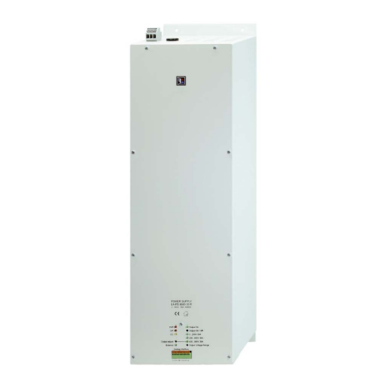
- Page 23 Handling the device © 2006, Elektro-Automatik GmbH & Co. KG Irrtümer und Änderungen vorbehalten Figure 3. Side view Figure 4. Front view © 2010, Elektro-Automatik GmbH & Co. KG...
-
Page 24: Manual Control
In order to select one, the pulling the pin to LOW (=off). power output has to be switched off first. Selecting a different range and subsequently switching the output on again will immediately set the output voltage that © 2010, Elektro-Automatik GmbH & Co. KG... - Page 25 For CMON, VMON External = Low (U <1V), Remote Activate external control Internal = High (U >4V) © 2006, Elektro-Automatik GmbH & Co. KG = 30V high Irrtümer und Änderungen vorbehalten Imax = -1mA at 5V Off = Low (U <1V),...
-
Page 26: Other Applications
An example of master-slave wiring with both, voltage and current: Note: if remote sense is used during Share bus opera- tion, it is advised to wire only the remote sense input of the determining unit. © 2010, Elektro-Automatik GmbH & Co. KG... - Page 28 EA-Elektro-Automatik GmbH & Co. KG Entwicklung - Produktion - Vertrieb Development - Production - Sales Helmholtzstraße 31-33 41747 Viersen Germany Telefon: 02162 / 37 85-0 Telefax: 02162 / 16 230 ea1974@elektroautomatik.de www.elektroautomatik.de...
Need help?
Do you have a question about the PS 800 R Series and is the answer not in the manual?
Questions and answers