Table of Contents
Advertisement
Available languages
Available languages
Quick Links
Advertisement
Chapters
Table of Contents

Related Manuals for Elektro-Automatik PSB 9000 3U Series


Summary of Contents for Elektro-Automatik PSB 9000 3U Series
- Page 1 Betriebsanleitung PSB 9000 3U Bidirektionale DC-Stromversorgung Achtung! Diese Anleitung gilt nur für Geräte mit TFT-Anzeige und einer Firmware ab „KE: Doc ID: PSB9DE 2.24“ (Standard) bzw. „KE: 2.08“ (GPIB), „HMI: 2.03“ und „DR: Revision: 03 1.6.5“. Date: 06/2018...
-
Page 3: Table Of Contents
..............61 2.3.3 Aufstellung des Gerätes ......32 3.6.4 Fernsteuerung über Analogschnittstelle 2.3.4 Anschließen an das Stromnetz (AC) ...33 (AS) ..............63 www.elektroautomatik.de EA Elektro-Automatik GmbH Telefon: 02162 / 3785-0 Seite 3 Helmholtzstr. 31-37 • 41747 Viersen Telefax: 02162 / 16230 ea1974@elektroautomatik.de... - Page 4 Defekte Netzsicherung tauschen ....93 4.2.2 Firmware-Aktualisierungen ......94 Ersatzableitstrommessung nach DIN VDE 0701-1 ..........94 SERVICE UND SUPPORT Reparaturen ..........95 Kontaktmöglichkeiten ........95 www.elektroautomatik.de EA Elektro-Automatik GmbH Telefon: 02162 / 3785-0 Seite 4 Helmholtzstr. 31-37 • 41747 Viersen Telefax: 02162 / 16230 ea1974@elektroautomatik.de...
-
Page 5: Allgemeines
Gewährleistung und Garantie Elektro-Automatik garantiert die Funktionsfähigkeit der angewandten Verfahrenstechnik und die ausgewiesenen Leistungsparameter. Die Gewährleistungsfrist beginnt mit der mängelfreien Übergabe. Die Garantiebestimmungen sind den allgemeinen Geschäftsbedingungen (AGB) der EA Elektro-Automatik GmbH zu entnehmen. Haftungsbeschränkungen Alle Angaben und Hinweise in dieser Anleitung wurden unter Berücksichtigung geltender Normen und Vorschrif- ten, des Stands der Technik sowie unserer langjährigen Erkenntnisse und Erfahrungen zusammengestellt. -
Page 6: Entsorgung Des Gerätes
• Ansprüche jeglicher Art wegen Schäden aus nicht bestimmungsgemäßer Verwendung sind ausgeschlossen • Für alle Schäden durch nicht bestimmungsgemäße Verwendung haftet allein der Betreiber www.elektroautomatik.de EA Elektro-Automatik GmbH Telefon: 02162 / 3785-0 Seite 6 Helmholtzstr. 31-37 • 41747 Viersen Telefax: 02162 / 16230... -
Page 7: Sicherheit
• Sämtliche Arten von Generatoren oder AC-USV-Stromversorgungen sind nicht als AC-Anschluß- quelle für diese Geräte zulässig. Es darf nur direkt an einem Stromnetz betrieben werden! www.elektroautomatik.de EA Elektro-Automatik GmbH Telefon: 02162 / 3785-0 Seite 7 Helmholtzstr. 31-37 • 41747 Viersen Telefax: 02162 / 16230 ea1974@elektroautomatik.de... -
Page 8: Verantwortung Des Bedieners
Als Fachpersonal gilt, wer aufgrund seiner beruflichen Ausbildung, Kenntnisse und Erfahrungen sowie Kenntnis der einschlägigen Bestimmungen in der Lage ist, die übertragenen Arbeiten ordnungsgemäß auszuführen, mög- liche Gefahren selbständig zu erkennen und Personen- oder Sachschäden zu vermeiden. www.elektroautomatik.de EA Elektro-Automatik GmbH Telefon: 02162 / 3785-0 Seite 8 Helmholtzstr. 31-37 • 41747 Viersen Telefax: 02162 / 16230 ea1974@elektroautomatik.de... -
Page 9: Alarmsignale
Farbiger TFT-Touchscreen mit Gorillaglas, 4.3“, 480 x 272 Punkte, kapazitiv Bedienelemente: 2 Drehknöpfe mit Tastfunktion, 1 Drucktaste Die Nennwerte des Gerätes bestimmen den maximal einstellbaren Bereich. www.elektroautomatik.de EA Elektro-Automatik GmbH Telefon: 02162 / 3785-0 Seite 9 Helmholtzstr. 31-37 • 41747 Viersen Telefax: 02162 / 16230... -
Page 10: Spezifische Technische Daten
4,92 V...5,08 V betragen. (2 RMS-Wert: NF 0...300 kHz, PP-Wert: HF 0...20MHz (3 Der Fehler der Anzeige addiert sich zum Fehler des Istwertes am DC-Anschluß www.elektroautomatik.de EA Elektro-Automatik GmbH Telefon: 02162 / 3785-0 Seite 10 Helmholtzstr. 31-37 • 41747 Viersen Telefax: 02162 / 16230 ea1974@elektroautomatik.de... - Page 11 (3 Technische Daten der Analogschnittstelle siehe „3.6.4.4 Spezifikation der Analogschnittstelle“ auf Seite 64 (4 Artikelnummer der Standardausführung, Geräte mit Optionen abweichend (5 Typischer Wert bei 100% Spannung und 100% Last www.elektroautomatik.de EA Elektro-Automatik GmbH Telefon: 02162 / 3785-0 Seite 11 Helmholtzstr. 31-37 • 41747 Viersen Telefax: 02162 / 16230 ea1974@elektroautomatik.de...
- Page 12 4,92 V...5,08 V betragen. (2 RMS-Wert: NF 0...300 kHz, PP-Wert: HF 0...20MHz (3 Der Fehler der Anzeige addiert sich zum Fehler des Istwertes am DC-Anschluß www.elektroautomatik.de EA Elektro-Automatik GmbH Telefon: 02162 / 3785-0 Seite 12 Helmholtzstr. 31-37 • 41747 Viersen Telefax: 02162 / 16230 ea1974@elektroautomatik.de...
- Page 13 (3 Technische Daten der Analogschnittstelle siehe „3.6.4.4 Spezifikation der Analogschnittstelle“ auf Seite 64 (4 Artikelnummer der Standardausführung, Geräte mit Optionen abweichend (5 Typischer Wert bei 100% Spannung und 100% Last www.elektroautomatik.de EA Elektro-Automatik GmbH Telefon: 02162 / 3785-0 Seite 13 Helmholtzstr. 31-37 • 41747 Viersen Telefax: 02162 / 16230 ea1974@elektroautomatik.de...
- Page 14 4,92 V...5,08 V betragen. (2 RMS-Wert: NF 0...300 kHz, PP-Wert: HF 0...20MHz (3 Der Fehler der Anzeige addiert sich zum Fehler des Istwertes am DC-Anschluß www.elektroautomatik.de EA Elektro-Automatik GmbH Telefon: 02162 / 3785-0 Seite 14 Helmholtzstr. 31-37 • 41747 Viersen Telefax: 02162 / 16230 ea1974@elektroautomatik.de...
- Page 15 (3 Technische Daten der Analogschnittstelle siehe „3.6.4.4 Spezifikation der Analogschnittstelle“ auf Seite 64 (4 Artikelnummer der Standardausführung, Geräte mit Optionen abweichend (5 Typischer Wert bei 100% Spannung und 100% Last www.elektroautomatik.de EA Elektro-Automatik GmbH Telefon: 02162 / 3785-0 Seite 15 Helmholtzstr. 31-37 • 41747 Viersen Telefax: 02162 / 16230 ea1974@elektroautomatik.de...
- Page 16 4,92 V...5,08 V betragen. (2 RMS-Wert: NF 0...300 kHz, PP-Wert: HF 0...20MHz (3 Der Fehler der Anzeige addiert sich zum Fehler des Istwertes am DC-Anschluß www.elektroautomatik.de EA Elektro-Automatik GmbH Telefon: 02162 / 3785-0 Seite 16 Helmholtzstr. 31-37 • 41747 Viersen Telefax: 02162 / 16230 ea1974@elektroautomatik.de...
- Page 17 (3 Technische Daten der Analogschnittstelle siehe „3.6.4.4 Spezifikation der Analogschnittstelle“ auf Seite 64 (4 Artikelnummer der Standardausführung, Geräte mit Optionen abweichend (5 Typischer Wert bei 100% Spannung und 100% Last www.elektroautomatik.de EA Elektro-Automatik GmbH Telefon: 02162 / 3785-0 Seite 17 Helmholtzstr. 31-37 • 41747 Viersen Telefax: 02162 / 16230 ea1974@elektroautomatik.de...
- Page 18 4,92 V...5,08 V betragen. (2 RMS-Wert: NF 0...300 kHz, PP-Wert: HF 0...20MHz (3 Der Fehler der Anzeige addiert sich zum Fehler des Istwertes am DC-Anschluß www.elektroautomatik.de EA Elektro-Automatik GmbH Telefon: 02162 / 3785-0 Seite 18 Helmholtzstr. 31-37 • 41747 Viersen Telefax: 02162 / 16230 ea1974@elektroautomatik.de...
- Page 19 (3 Technische Daten der Analogschnittstelle siehe „3.6.4.4 Spezifikation der Analogschnittstelle“ auf Seite 64 (4 Artikelnummer der Standardausführung, Geräte mit Optionen abweichend (5 Typischer Wert bei 100% Spannung und 100% Last www.elektroautomatik.de EA Elektro-Automatik GmbH Telefon: 02162 / 3785-0 Seite 19 Helmholtzstr. 31-37 • 41747 Viersen Telefax: 02162 / 16230 ea1974@elektroautomatik.de...
-
Page 20: Ansichten
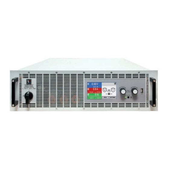
PSB 9000 3U Serie 1.8.4 Ansichten Bild 1 - Vorderseite Bild 2 - Rückseite (Standardausführung) www.elektroautomatik.de EA Elektro-Automatik GmbH Telefon: 02162 / 3785-0 Seite 20 Helmholtzstr. 31-37 • 41747 Viersen Telefax: 02162 / 16230 ea1974@elektroautomatik.de... - Page 21 PSB 9000 3U Serie www.elektroautomatik.de EA Elektro-Automatik GmbH Telefon: 02162 / 3785-0 Seite 21 Helmholtzstr. 31-37 • 41747 Viersen Telefax: 02162 / 16230 ea1974@elektroautomatik.de...
- Page 22 PSB 9000 3U Serie Bild 5 - Ansicht von oben www.elektroautomatik.de EA Elektro-Automatik GmbH Telefon: 02162 / 3785-0 Seite 22 Helmholtzstr. 31-37 • 41747 Viersen Telefax: 02162 / 16230 ea1974@elektroautomatik.de...
-
Page 23: Bedienelemente
Bedienung oder Fernsteuerung Steckplatz für USB-Sticks Dient zur Aufnahme handelsüblicher USB-Sticks. Siehe Abschnitt „1.9.6.5. USB-Port (Vorderseite)“ für weitere Informationen. www.elektroautomatik.de EA Elektro-Automatik GmbH Telefon: 02162 / 3785-0 Seite 23 Helmholtzstr. 31-37 • 41747 Viersen Telefax: 02162 / 16230... -
Page 24: Aufbau Und Funktion
Share & Sense Power block 1...3 Controller (DR) ≈ ≈ Commu- nication (KE) PSB 9000 Block diagram Anybus / GPIB (opt.) www.elektroautomatik.de EA Elektro-Automatik GmbH Telefon: 02162 / 3785-0 Seite 24 Helmholtzstr. 31-37 • 41747 Viersen Telefax: 02162 / 16230 ea1974@elektroautomatik.de... -
Page 25: Lieferumfang
Modellen dieser Serie zwecks Leistungsaufstockung. Sie können vom Zusätzliche Slave-Einheiten Anwender auf Anfrage nachbestellt und selbst installiert werden. Im Lieferumfang befindet sich auch ein Patchkabel für die Anbindung des neuen Slaves an den Master-Slave-Bus. www.elektroautomatik.de EA Elektro-Automatik GmbH Telefon: 02162 / 3785-0 Seite 25 Helmholtzstr. 31-37 • 41747 Viersen Telefax: 02162 / 16230 ea1974@elektroautomatik.de... -
Page 26: Die Bedieneinheit (Hmi)
0-110% Nenn OVP, OCP, OPP (bezogen auf U, I und P) Untere Grenze für Widerstandssollwerte variiert. Siehe Tabelle in Abschnitt 1.8.3. www.elektroautomatik.de EA Elektro-Automatik GmbH Telefon: 02162 / 3785-0 Seite 26 Helmholtzstr. 31-37 • 41747 Viersen Telefax: 02162 / 16230... - Page 27 Die Drehknöpfe haben eine Tastfunktion, die überall wo Werte gestellt werden können, zum Verschieben des Cursors von niederwertigen zu höherwertigen Dezimalpositionen (rotierend) des einzustellenden Wertes dient: www.elektroautomatik.de EA Elektro-Automatik GmbH Telefon: 02162 / 3785-0 Seite 27 Helmholtzstr. 31-37 • 41747 Viersen Telefax: 02162 / 16230 ea1974@elektroautomatik.de...
- Page 28 Werte aufgezeichnet als beim „normalen“ USB-Logging. mpp_result_<nr>.csv Ergebnisdaten des MPP-Tracking-Modus‘ 4 als Tabelle mit 100 Wertegruppen (Umpp, Impp, Pmpp) www.elektroautomatik.de EA Elektro-Automatik GmbH Telefon: 02162 / 3785-0 Seite 28 Helmholtzstr. 31-37 • 41747 Viersen Telefax: 02162 / 16230 ea1974@elektroautomatik.de...
-
Page 29: Usb-Port (Rückseite)
Der Eingangsspannungsbereich der Sollwerte bzw. der Ausgangsspannungsbereich der Monitorwerte und der Referenzspannung kann im Einstellungsmenü des Gerätes zwischen 0...5 V und 0...10 V für jeweils 0...100% umgeschaltet werden. www.elektroautomatik.de EA Elektro-Automatik GmbH Telefon: 02162 / 3785-0 Seite 29 Helmholtzstr. 31-37 • 41747 Viersen Telefax: 02162 / 16230 ea1974@elektroautomatik.de... -
Page 30: Share-Bus-Anschluß
Der GPIB-Anschluß dient zur Verbindung zu einem PC bzw. anderen GPIB-Anschlüs- sen über handelsübliche GPIB-Kabel (gerade oder gewinkelt). Bei Verwendung von gewinkelten Steckern am GPIB-Kabel ist der USB-Anschluß nicht gleichzeitig zugänglich. www.elektroautomatik.de EA Elektro-Automatik GmbH Telefon: 02162 / 3785-0 Seite 30 Helmholtzstr. 31-37 • 41747 Viersen Telefax: 02162 / 16230... -
Page 31: Installation Und Inbetriebnahme
Richtlinien des örtlichen Energieversorgers betrieben werden und es ist ggf. vor der Installation, spätestens aber vor der Inbetriebnahme zu prüfen, ob ein sogenannter Netz- und Anlagenschutz installiert werden muß! www.elektroautomatik.de EA Elektro-Automatik GmbH Telefon: 02162 / 3785-0 Seite 31 Helmholtzstr. 31-37 • 41747 Viersen Telefax: 02162 / 16230 ea1974@elektroautomatik.de... -
Page 32: Vorbereitung
Gerät auch auf jeglicher horizontaler Fläche als Tischgerät betrieben werden kann. Zulässige und unzulässige Aufstellpositionen: Aufstellfläche www.elektroautomatik.de EA Elektro-Automatik GmbH Telefon: 02162 / 3785-0 Seite 32 Helmholtzstr. 31-37 • 41747 Viersen Telefax: 02162 / 16230... -
Page 33: Anschließen An Das Stromnetz (Ac)
Spannungsabfall aufgrund des Leitungswiderstandes. Daher sollte die Netzzuleitung immer so kurz wie möglich gehalten werden. Bild 7 - Beispiel für ein Netzanschlußkabel (nicht im Lieferumfang enthalten) www.elektroautomatik.de EA Elektro-Automatik GmbH Telefon: 02162 / 3785-0 Seite 33 Helmholtzstr. 31-37 • 41747 Viersen Telefax: 02162 / 16230 ea1974@elektroautomatik.de... - Page 34 Mehrere Geräte (5 kW & 10 kW), ungleichmäßig PSB 1 PSB 1 10kW PSB 2 PSB 2 10kW 10kW PS 3 PSB 3 10kW www.elektroautomatik.de EA Elektro-Automatik GmbH Telefon: 02162 / 3785-0 Seite 34 Helmholtzstr. 31-37 • 41747 Viersen Telefax: 02162 / 16230 ea1974@elektroautomatik.de...
- Page 35 Verbraucher 2 Verbraucher 2 Bei einer größeren Anzahl rückspeisender Geräte am selben Strang der Installation erhöht sich der Gesamtstrom pro Phase entsprechend. www.elektroautomatik.de EA Elektro-Automatik GmbH Telefon: 02162 / 3785-0 Seite 35 Helmholtzstr. 31-37 • 41747 Viersen Telefax: 02162 / 16230...
-
Page 36: Anschließen Von Dc-Lasten Oder Dc-Quellen
Typ 2: Modelle ab 500 V Ausgangsspannung Schraubverbindung M8 an Metallschiene Schraubverbindung M6 an Metallschiene Empfehlung: Ringkabelschuhe mit 8er Loch Empfehlung: Ringkabelschuhe mit 6er Loch www.elektroautomatik.de EA Elektro-Automatik GmbH Telefon: 02162 / 3785-0 Seite 36 Helmholtzstr. 31-37 • 41747 Viersen Telefax: 02162 / 16230 ea1974@elektroautomatik.de... -
Page 37: Erdung Des Dc-Anschlusses
• (+) Sense darf nur am (+) der Last bzw. Quelle und (–) Sense nur am (–) der Last bzw. Quelle angeschlossen werden. Ansonsten können beide Systeme beschädigt werden. • Bei Master-Slave-Betrieb sollte die Fernfühlung nur am Master-Gerät erfolgen www.elektroautomatik.de EA Elektro-Automatik GmbH Telefon: 02162 / 3785-0 Seite 37 Helmholtzstr. 31-37 • 41747 Viersen Telefax: 02162 / 16230 ea1974@elektroautomatik.de... -
Page 38: Installation Eines Schnittstellen-Moduls
Plastiknasen, die auf dem letzten Mil- packt werden, um es her- limeter des Einschubweges auf der grünen auszuziehen. Platine einrasten müssen, damit das Modul auf der Rückwand des Gerätes richtig aufliegt. www.elektroautomatik.de EA Elektro-Automatik GmbH Telefon: 02162 / 3785-0 Seite 38 Helmholtzstr. 31-37 • 41747 Viersen Telefax: 02162 / 16230 ea1974@elektroautomatik.de... -
Page 39: Anschließen Der Analogen Schnittstelle
Falls der oben beschriebene CDC-Treiber auf Ihrem System nicht vorhanden ist oder aus irgendeinem Grund nicht richtig funktionieren sollte, können kommerzielle Anbieter Abhilfe schaffen. Suchen und finden Sie dazu im Internet diverse Anbieter mit den Schlüsselwörtern „cdc driver windows“ oder „cdc driver linux“ oder „cdc driver macos“. www.elektroautomatik.de EA Elektro-Automatik GmbH Telefon: 02162 / 3785-0 Seite 39 Helmholtzstr. 31-37 • 41747 Viersen Telefax: 02162 / 16230 ea1974@elektroautomatik.de... -
Page 40: Erstinbetriebnahme
Erstinbetriebnahme. Siehe daher auch „2.3.12. Erstinbetriebnahme“. Erst nach erfolgreicher Überprüfung des Gerätes nach den gelisteten Punkten darf es wie gewohnt in Betrieb genommen werden. www.elektroautomatik.de EA Elektro-Automatik GmbH Telefon: 02162 / 3785-0 Seite 40 Helmholtzstr. 31-37 • 41747 Viersen Telefax: 02162 / 16230 ea1974@elektroautomatik.de... -
Page 41: Bedienung Und Verwendung
Einbruchs oder der Erhöhung ist modellabhängig von der aktuellen Ausgangspannung, der Ausgangskapazität und dem eigentlichen Lastsprung und kann daher nicht genau oder pauschal angegeben werden. www.elektroautomatik.de EA Elektro-Automatik GmbH Telefon: 02162 / 3785-0 Seite 41 Helmholtzstr. 31-37 • 41747 Viersen Telefax: 02162 / 16230 ea1974@elektroautomatik.de... -
Page 42: Stromregelung / Konstantstrom / Strombegrenzung
Fernfühlung am DC-Ausgang abgibt, wird vom Gerät nicht erfaßt und dadurch könnte das Gerät bereits in Leistungsbegrenzung sein, ohne dies explizit durch „CP“ anzuzeigen. Im Senke-Betrieb wird der CP-Modus korrekt angezeigt, für die der externen Quelle entnommenen Leistung. www.elektroautomatik.de EA Elektro-Automatik GmbH Telefon: 02162 / 3785-0 Seite 42 Helmholtzstr. 31-37 • 41747 Viersen Telefax: 02162 / 16230 ea1974@elektroautomatik.de... -
Page 43: Innenwiderstandsregelung (Quelle-Betrieb)
Gerät eingestellten Strom. Solange der DC-Eingang eingeschaltet und Konstantwiderstandbetrieb aktiv ist, wird der Zustand „CR-Betrieb aktiv“ als Kürzel CR auf der grafischen Anzeige ausgegeben, kann aber auch als Status über die digitalen Schnittstellen ausgelesen werden. www.elektroautomatik.de EA Elektro-Automatik GmbH Telefon: 02162 / 3785-0 Seite 43 Helmholtzstr. 31-37 • 41747 Viersen Telefax: 02162 / 16230... -
Page 44: Umschaltung Der Betriebsart Quelle <-> Senke
Möchte man eine der beiden Betriebsarten explizit fahren, also ohne automatischen Wechsel, müßte man: • für Nur-Quelle-Betrieb den Stromsollwert der Senke auf 0 stellen • für Nur-Senke-Betrieb den Spannungssollwert auf 0 stellen www.elektroautomatik.de EA Elektro-Automatik GmbH Telefon: 02162 / 3785-0 Seite 44 Helmholtzstr. 31-37 • 41747 Viersen Telefax: 02162 / 16230 ea1974@elektroautomatik.de... -
Page 45: Alarmzustände
Diese Schutzfunktion dient nicht dem Schutz des Gerätes, sondern dem Schutz der angeschlossenen Last (Quelle-Betrieb) bzw. der externen Quelle (Senke-Betrieb), falls diese durch zu hohe Leistungsaufnahme beschädigt werden könnte. www.elektroautomatik.de EA Elektro-Automatik GmbH Telefon: 02162 / 3785-0 Seite 45 Helmholtzstr. 31-37 • 41747 Viersen Telefax: 02162 / 16230 ea1974@elektroautomatik.de... -
Page 46: Safety Ovp
Bei angeschlossener Fernfühlung ist, zumindest bei Quelle-Betrieb, die Ausgangsspannung um den Betrag der Ausregelung höher. Daher greift der Safety OVP ggf. schon bei einer Ausgangsspannung unter 60 V. www.elektroautomatik.de EA Elektro-Automatik GmbH Telefon: 02162 / 3785-0 Seite 46 Helmholtzstr. 31-37 • 41747 Viersen Telefax: 02162 / 16230 ea1974@elektroautomatik.de... -
Page 47: Manuelle Bedienung
Die Menüstruktur ist auf den folgenden Seiten als Schema dargestellt. Einige Einstellparameter sind selbsterklärend, andere nicht. Diese werden auf den nachfolgenden Seite im Einzelnen erläutert. www.elektroautomatik.de EA Elektro-Automatik GmbH Telefon: 02162 / 3785-0 Seite 47 Helmholtzstr. 31-37 • 41747 Viersen Telefax: 02162 / 16230... - Page 48 PSB 9000 3U Serie www.elektroautomatik.de EA Elektro-Automatik GmbH Telefon: 02162 / 3785-0 Seite 48 Helmholtzstr. 31-37 • 41747 Viersen Telefax: 02162 / 16230 ea1974@elektroautomatik.de...
- Page 49 PSB 9000 3U Serie www.elektroautomatik.de EA Elektro-Automatik GmbH Telefon: 02162 / 3785-0 Seite 49 Helmholtzstr. 31-37 • 41747 Viersen Telefax: 02162 / 16230 ea1974@elektroautomatik.de...
- Page 50 PSB 9000 3U Serie www.elektroautomatik.de EA Elektro-Automatik GmbH Telefon: 02162 / 3785-0 Seite 50 Helmholtzstr. 31-37 • 41747 Viersen Telefax: 02162 / 16230 ea1974@elektroautomatik.de...
- Page 51 PSB 9000 3U Serie www.elektroautomatik.de EA Elektro-Automatik GmbH Telefon: 02162 / 3785-0 Seite 51 Helmholtzstr. 31-37 • 41747 Viersen Telefax: 02162 / 16230 ea1974@elektroautomatik.de...
- Page 52 Befehl veranlaßtem Beenden der Fernsteuerung sein soll. • AUS = nach dem Verlassen der Fernsteuerung immer aus • AUTO = Zustand wird beibehalten www.elektroautomatik.de EA Elektro-Automatik GmbH Telefon: 02162 / 3785-0 Seite 52 Helmholtzstr. 31-37 • 41747 Viersen Telefax: 02162 / 16230...
- Page 53 Diese Menüseite zeigt eine Übersicht gerätebezogener Daten wie Serienummer, Artikelnummer usw., sowie eine Alarmhistorie (Anzahl aufgetretener Gerätealarme seit Einschalten des Gerätes) an. 3.5.3.6 Menü „Funkt.Generator“ Siehe „3.11 Der Funktionsgenerator“ auf Seite 72. www.elektroautomatik.de EA Elektro-Automatik GmbH Telefon: 02162 / 3785-0 Seite 53 Helmholtzstr. 31-37 • 41747 Viersen Telefax: 02162 / 16230 ea1974@elektroautomatik.de...
- Page 54 „Manuell“ zu wählen. 100MBit Host-Name Beliebig wählbarer Hostname (Standard: Client) Domäne Beliebig wählbare Domäne (Standard: Workgroup) TCP Keep-Alive TCP Keep-alive aktivieren www.elektroautomatik.de EA Elektro-Automatik GmbH Telefon: 02162 / 3785-0 Seite 54 Helmholtzstr. 31-37 • 41747 Viersen Telefax: 02162 / 16230 ea1974@elektroautomatik.de...
- Page 55 Die Baudrate ist einstellbar, weitere serielle Einstellungen sind wie folgt festgelegt: 8 Datenbits, 1 Stopbit, Parität = keine Baudrateneinstellungen: 2400, 4800, 9600, 19200, 38400, 57600, 115200 www.elektroautomatik.de EA Elektro-Automatik GmbH Telefon: 02162 / 3785-0 Seite 55 Helmholtzstr. 31-37 • 41747 Viersen Telefax: 02162 / 16230 ea1974@elektroautomatik.de...
- Page 56 Sobald dann eine erfolgt, schaltet sich die Beleuchtung automatisch wieder ein. Weiterhin kann die Helligkeit der Hintergrundbeleuchtung eingestellt werden. Limits Sperre Siehe „3.9 Einstellgrenzen (Limits) sperren“ auf Seite 70 www.elektroautomatik.de EA Elektro-Automatik GmbH Telefon: 02162 / 3785-0 Seite 56 Helmholtzstr. 31-37 • 41747 Viersen Telefax: 02162 / 16230...
-
Page 57: Einstellgrenzen (Limits)
B. Zuordnung U/I gewählt, auch die Leistung durch Direkteingabe stellen. Siehe dazu 3.5.6. Was das Gerät bei eingeschaltetem DC-Anschluß dann tatsächlich als aktuelle Regelungsart bzw. Betriebsart einstellt, hängt nur von den Sollwerten ab. Mehr Informationen dazu finden Sie in „3.3. Regelungsarten“. www.elektroautomatik.de EA Elektro-Automatik GmbH Telefon: 02162 / 3785-0 Seite 57 Helmholtzstr. 31-37 • 41747 Viersen Telefax: 02162 / 16230... -
Page 58: Sollwerte Manuell Einstellen
Wird ein Wert eingeben, der höher als die jeweilige Einstellgrenze ist, erscheint ein Hinweis und der eingegebene Wert wird auf 0 zurückgesetzt und nicht übernommen. www.elektroautomatik.de EA Elektro-Automatik GmbH Telefon: 02162 / 3785-0 Seite 58 Helmholtzstr. 31-37 • 41747 Viersen Telefax: 02162 / 16230 ea1974@elektroautomatik.de... -
Page 59: Dc-Anschluß Ein- Oder Ausschalten
Fehler kommen (Stick voll, Stick abgezogen), erscheint ein entsprechendes Symbol . Mit jedem manuellen Stopp oder Ausschalten des DC-Anschlusses wird das Logging beendet und die aufgezeichnete Log- Datei geschlossen. www.elektroautomatik.de EA Elektro-Automatik GmbH Telefon: 02162 / 3785-0 Seite 59 Helmholtzstr. 31-37 • 41747 Viersen Telefax: 02162 / 16230... - Page 60 • Bei Einstellung „Manueller Start/Stopp“ zeichnet das Gerät bei Alarmen weiter auf, damit so z. B. die Dauer von temporären Alarmen wie OT und PF ermittelt werden kann www.elektroautomatik.de EA Elektro-Automatik GmbH Telefon: 02162 / 3785-0 Seite 60 Helmholtzstr. 31-37 • 41747 Viersen Telefax: 02162 / 16230 ea1974@elektroautomatik.de...
-
Page 61: Fernsteuerung
* Für technische Details zu den einzelnen Modulen siehe separate Dokumentation „Programmieranleitung Modbus & SCPI“ Modelle mit installierter Option 3W bieten neben dem USB-Port einen fest installierten GPIB-Anschluß. www.elektroautomatik.de EA Elektro-Automatik GmbH Telefon: 02162 / 3785-0 Seite 61 Helmholtzstr. 31-37 • 41747 Viersen Telefax: 02162 / 16230 ea1974@elektroautomatik.de... - Page 62 Details zur Programmierung der Schnittstellen, die Kommunikationsprotokolle usw. sind in der externen Doku- mentation „Programmieranleitung ModBus & SCPI“ zu finden, die mit dem Gerät auf einem USB-Stick mitgeliefert wird bzw. als Download auf der Webseite des Geräteherstellers verfügbar ist. www.elektroautomatik.de EA Elektro-Automatik GmbH Telefon: 02162 / 3785-0 Seite 62 Helmholtzstr. 31-37 • 41747 Viersen Telefax: 02162 / 16230 ea1974@elektroautomatik.de...
-
Page 63: Fernsteuerung Über Analogschnittstelle (As)
Zum Anderen wird eine maximale Abtastrate von 500 Hz bedingt. Das bedeutet, die analoge Schnittstelle kann 500 mal pro Sekunde Sollwerte und deren Änderungen, sowie Zustände an den digitalen Pins verarbeiten. www.elektroautomatik.de EA Elektro-Automatik GmbH Telefon: 02162 / 3785-0 Seite 63 Helmholtzstr. - Page 64 *** Nur eins von beiden Signalen mögliche, siehe 3.5.3.1 **** Nur während Fernsteuerung ***** Der Fehler eines Sollwerteinganges addiert sich zum allgemeinen Fehler des zugehörigen Wertes am DC-Anschluß des Gerätes www.elektroautomatik.de EA Elektro-Automatik GmbH Telefon: 02162 / 3785-0 Seite 64 Helmholtzstr. 31-37 • 41747 Viersen Telefax: 02162 / 16230 ea1974@elektroautomatik.de...
- Page 65 Einstellung „Analogschnittstelle REM-SB = normal“ entspricht das der Vorgabe „DC-Anschluß einschalten“. Das heißt, sobald mit Pin „REMOTE“ auf Fernsteuerung umgeschaltet wird, schaltet der DC-Anschluß ein! www.elektroautomatik.de EA Elektro-Automatik GmbH Telefon: 02162 / 3785-0 Seite 65 Helmholtzstr. 31-37 • 41747 Viersen Telefax: 02162 / 16230 ea1974@elektroautomatik.de...
- Page 66 Spannung intern erzeugt wurde oder von extern eingespeist ist • ist der Sollwert VSEL höher als die Spannung DC-Anschluß, schaltet das Gerät auf Quelle-Betrieb um www.elektroautomatik.de EA Elektro-Automatik GmbH Telefon: 02162 / 3785-0 Seite 66 Helmholtzstr. 31-37 • 41747 Viersen Telefax: 02162 / 16230 ea1974@elektroautomatik.de...
-
Page 67: Alarme Und Überwachung
OverCurrent Ausgangsstrom am DC-Anschluß die eingestellte 0 A...1,1*I Digitale Schnitt- Nenn Protection Schwelle erreicht. Außerdem wird der DC-Anschluß stellen ausgeschaltet. www.elektroautomatik.de EA Elektro-Automatik GmbH Telefon: 02162 / 3785-0 Seite 67 Helmholtzstr. 31-37 • 41747 Viersen Telefax: 02162 / 16230 ea1974@elektroautomatik.de... - Page 68 In der nächsten Menüseite das Feld „Alarmton“ berühren. In der Einstellungsseite tippen Sie auf das Symbol, um den Alarmton entweder ein- oder auszuschalten und bestätigen dann mit www.elektroautomatik.de EA Elektro-Automatik GmbH Telefon: 02162 / 3785-0 Seite 68 Helmholtzstr. 31-37 • 41747 Viersen Telefax: 02162 / 16230 ea1974@elektroautomatik.de...
- Page 69 Die Einstellwerte können auch direkt über eine Zehnertastatur eingegeben werden. Diese erscheint, wenn man auf der jeweiligen Seite unten auf das Bedienfeld „Direkteingabe“ tippt. www.elektroautomatik.de EA Elektro-Automatik GmbH Telefon: 02162 / 3785-0 Seite 69 Helmholtzstr. 31-37 • 41747 Viersen Telefax: 02162 / 16230 ea1974@elektroautomatik.de...
-
Page 70: Bedieneinheit (Hmi) Sperren
Auf der folgenden Seite betätigen Sie das Bedienfeld „Entsperren“ und werden dann aufgefordert, die vierstellige PIN einzugeben. Deaktivieren Sie die Sperre nach der Eingabe der korrekten PIN mit ENTER. www.elektroautomatik.de EA Elektro-Automatik GmbH Telefon: 02162 / 3785-0 Seite 70 Helmholtzstr. 31-37 • 41747 Viersen Telefax: 02162 / 16230 ea1974@elektroautomatik.de... -
Page 71: Nutzerprofile Laden Und Speichern
In der nun erscheinenden Auswahl (siehe rechts) wählen Sie zwischen Nutzerprofil 1-5 aus, in welches Sie speichern wollen. Das gewählte Nutzerprofil wird daraufhin angezeigt. Sie können hier die Einstellungen und Werte noch einmal kontrollieren, jedoch nicht verändern. Speichern Sie mit Bedienfeld www.elektroautomatik.de EA Elektro-Automatik GmbH Telefon: 02162 / 3785-0 Seite 71 Helmholtzstr. 31-37 • 41747 Viersen Telefax: 02162 / 16230 ea1974@elektroautomatik.de... -
Page 72: Der Funktionsgenerator
Amplitude und Gerätemodell ab. Die Auswirkungen der Leistungsstufen können teilweise kompensiert werden. Im Quelle-Betrieb und bei dynamischer Spannungserzeugung, auf welche die Kapazitäten den größten Einfluß haben, kann eine zusätzliche Last am DC-Anschluß zu geringeren Anstiegs- und Abfallzeiten der Spannung führen. Diese Modifikation wirkt sich positiv auf periodisch wiederholte Funktionen, wie Rechteck oder Sinus, aus. www.elektroautomatik.de EA Elektro-Automatik GmbH Telefon: 02162 / 3785-0 Seite 72 Helmholtzstr. 31-37 • 41747 Viersen Telefax: 02162 / 16230... -
Page 73: Arbeitsweise
Kapazitäten wenn er ungleich 0 eingestellt wurde und ist daher besonders sorgfältig zu wählen, weil es hier auch um die Kabelquerschnitte der Leitungen zur Last geht. Empfehlung: I Senke = I der Kurve. www.elektroautomatik.de EA Elektro-Automatik GmbH Telefon: 02162 / 3785-0 Seite 73 Helmholtzstr. 31-37 • 41747 Viersen Telefax: 02162 / 16230... -
Page 74: Manuelle Bedienung
Bei Gerätealarmen (Überspannung, Übertemperatur usw.), Schutzfunktionen (OPP, OCP) oder Events mit Aktion= Alarm stoppt der Funktionsablauf automatisch, der DC-Anschluß wird ausgeschaltet und der Alarm gemeldet. www.elektroautomatik.de EA Elektro-Automatik GmbH Telefon: 02162 / 3785-0 Seite 74 Helmholtzstr. 31-37 • 41747 Viersen Telefax: 02162 / 16230 ea1974@elektroautomatik.de... -
Page 75: Sinus-Funktion
- A) Nenn Offs = Offset, bezogen auf den Fußpunkt des Dreiecks I(Offs) - (I - A)...+(I - A) Nenn Nenn 0,1 ms...36000 s Anstiegszeit Δt der ansteigenden Flanke des Dreiecksignals 0,1 ms...36000 s Abfallzeit Δt der abfallenden Flanke des Dreiecksignals www.elektroautomatik.de EA Elektro-Automatik GmbH Telefon: 02162 / 3785-0 Seite 75 Helmholtzstr. 31-37 • 41747 Viersen Telefax: 02162 / 16230 ea1974@elektroautomatik.de... -
Page 76: Rechteck-Funktion
Für den Puls ergäben sich dann bei 80% Duty cycle t1 = 40 ms*0,8 = 32 ms. Die Zeit t2 wäre dann mit 8 ms zu setzen. www.elektroautomatik.de EA Elektro-Automatik GmbH Telefon: 02162 / 3785-0 Seite 76 Helmholtzstr. 31-37 • 41747 Viersen Telefax: 02162 / 16230 ea1974@elektroautomatik.de... -
Page 77: Trapez-Funktion
Anzahl der Abläufe der Kurve Zeit t1 0,1 ms...36000 s Zeit nach Ablauf der Kurve, bevor wiederholt wird (Zyklen <> 1) www.elektroautomatik.de EA Elektro-Automatik GmbH Telefon: 02162 / 3785-0 Seite 77 Helmholtzstr. 31-37 • 41747 Viersen Telefax: 02162 / 16230... -
Page 78: Arbiträr-Funktion
Man kann nicht eine beliebig kleine Änderung über eine beliebig große Zeit hinweg erzeugen. In so einem Fall lehnt das Gerät unpassende Einstellungen mit einer Meldung ab. www.elektroautomatik.de EA Elektro-Automatik GmbH Telefon: 02162 / 3785-0 Seite 78 Helmholtzstr. 31-37 • 41747 Viersen Telefax: 02162 / 16230 ea1974@elektroautomatik.de... - Page 79 Sinuswelle aus, die mit jeder neu angefangenen Sinuswelle kleiner wird, über den Zeitraum des Sequenzablaufs mit Sequenzpunktzeit x. f (start) f (end) Seq.Zeit www.elektroautomatik.de EA Elektro-Automatik GmbH Telefon: 02162 / 3785-0 Seite 79 Helmholtzstr. 31-37 • 41747 Viersen Telefax: 02162 / 16230 ea1974@elektroautomatik.de...
- Page 80 Halb- welle enden sowie der zweite mit der negativen beginnen, wie links gezeigt. www.elektroautomatik.de EA Elektro-Automatik GmbH Telefon: 02162 / 3785-0 Seite 80 Helmholtzstr. 31-37 • 41747 Viersen Telefax: 02162 / 16230...
- Page 81 Strom geladen werden, weil sie für beide paßt. Die Benamung ist jedoch durch einen Filter eindeutig gemacht, das heißt man kann nicht Arbiträr --> U im Funktionsgeneratormenü wählen und dann eine WAVE_I laden. Diese würde gar nicht erst aufgelistet. www.elektroautomatik.de EA Elektro-Automatik GmbH Telefon: 02162 / 3785-0 Seite 81 Helmholtzstr. 31-37 • 41747 Viersen Telefax: 02162 / 16230 ea1974@elektroautomatik.de...
-
Page 82: Rampen-Funktion
10 h nach Erreichen des Rampenendes stoppt die Funktion automatisch (I = 0 A, wenn Strom- rampe), sofern sie nicht vorher schon anderweitig gestoppt wurde. www.elektroautomatik.de EA Elektro-Automatik GmbH Telefon: 02162 / 3785-0 Seite 82 Helmholtzstr. 31-37 • 41747 Viersen Telefax: 02162 / 16230 ea1974@elektroautomatik.de... -
Page 83: Batterietest-Funktion
Belastung kurz unter die Schwelle U-DV gelangt und der Test sofort beendet wird. Daher sollt hier die U-DV ent- sprechend höher eingestellt werden. Grafische Verdeutlichung beider Modi: U, I U, I U-DV U-DV Entladestrom Entladestrom Start Stop Start Stop Statisch Dynamisch www.elektroautomatik.de EA Elektro-Automatik GmbH Telefon: 02162 / 3785-0 Seite 83 Helmholtzstr. 31-37 • 41747 Viersen Telefax: 02162 / 16230 ea1974@elektroautomatik.de... - Page 84 V • Entnommene Kapazität in Ah • Entnommene Energie in Wh • Testzeit in HH:MM:SS,MS • Reglerstatus (CC, CP, CR) www.elektroautomatik.de EA Elektro-Automatik GmbH Telefon: 02162 / 3785-0 Seite 84 Helmholtzstr. 31-37 • 41747 Viersen Telefax: 02162 / 16230 ea1974@elektroautomatik.de...
-
Page 85: Mpp-Tracking-Funktion
Eingangsbereich eingeschränkt ist. Voltage Die MPP-Tracking-Funktion bietet vier Modi zur Auswahl. Die Eingabe von Werten erfolgt hier nur über Direkteingabe per Touchscreen. www.elektroautomatik.de EA Elektro-Automatik GmbH Telefon: 02162 / 3785-0 Seite 85 Helmholtzstr. 31-37 • 41747 Viersen Telefax: 02162 / 16230 ea1974@elektroautomatik.de... - Page 86 Meßintervall für die Erfassung von U und I während der Suche nach dem MPP ΔP 0 W...0,5 P Regeltoleranz unterhalb des MPP Nenn www.elektroautomatik.de EA Elektro-Automatik GmbH Telefon: 02162 / 3785-0 Seite 86 Helmholtzstr. 31-37 • 41747 Viersen Telefax: 02162 / 16230 ea1974@elektroautomatik.de...
-
Page 87: Fernsteuerung Des Funktionsgenerators
• Der Funktionsgenerator ist nicht über die analoge Schnittstelle fernbedienbar • Der Funktionsgenerator ist nicht verfügbar, wenn der sog. Widerstands-Betrieb (R-Modus) aktiviert wurde • Die Funktion „Batterietest“ ist nicht für Fernsteuerung verfügbar www.elektroautomatik.de EA Elektro-Automatik GmbH Telefon: 02162 / 3785-0 Seite 87 Helmholtzstr. 31-37 • 41747 Viersen Telefax: 02162 / 16230 ea1974@elektroautomatik.de... -
Page 88: Weitere Anwendungen
Die Verwendung des Share-Bus‘ bedingt zumindest die Verbindung der DC-Minus-An- schlüsse der Geräte als Bezugspunkt. • Der Share-Bus ist beim Betrieb mehrerer PSB 9000 in Parallelschaltung unerläßlich, da über ihn die untergeordneten Einheiten zwecks Quelle-/Senke-Betrieb definiert werden www.elektroautomatik.de EA Elektro-Automatik GmbH Telefon: 02162 / 3785-0 Seite 88 Helmholtzstr. 31-37 • 41747 Viersen Telefax: 02162 / 16230 ea1974@elektroautomatik.de... - Page 89 Gerät fest. Die Warnmeldung bestätigen Sie mit OK, ansonsten wird die Änderung nicht übernommen. Übernehmen Sie die Einstellungen mit Bedienfeld und verlassen Sie das Einstellmenü. Das Slave-Gerät ist hiermit fertig konfiguriert. Für jedes weitere Slave-Gerät genauso wiederholen. www.elektroautomatik.de EA Elektro-Automatik GmbH Telefon: 02162 / 3785-0 Seite 89 Helmholtzstr. 31-37 • 41747 Viersen Telefax: 02162 / 16230...
- Page 90 Um alle diese Werte nach dem Verlassen des MS-Betriebs schnell wieder herstellen zu können, wird die Verwendung von Nutzerprofilen empfohlen (siehe „3.10. Nutzerprofile laden und spei- chern“) • www.elektroautomatik.de EA Elektro-Automatik GmbH Telefon: 02162 / 3785-0 Seite 90 Helmholtzstr. 31-37 • 41747 Viersen Telefax: 02162 / 16230...
- Page 91 System arbeiten soll erforderlich sein, bei den inaktiven Einheiten den Share-Bus-Stecker abzuziehen, weil sie auch im ausgeschaltetem Zustand durch ihre Impedanz auf den Share-Bus wirken und ihn negativ beeinflussen könnten. www.elektroautomatik.de EA Elektro-Automatik GmbH Telefon: 02162 / 3785-0 Seite 91 Helmholtzstr. 31-37 • 41747 Viersen Telefax: 02162 / 16230 ea1974@elektroautomatik.de...
-
Page 92: Reihenschaltung
Folgendes gilt es zu beachten: • Kein Verpolungsschutz! Das Gerät wird durch eine verpolt angeschlossene Batterie beschädigt, auch wenn es nicht eingeschaltet ist. www.elektroautomatik.de EA Elektro-Automatik GmbH Telefon: 02162 / 3785-0 Seite 92 Helmholtzstr. 31-37 • 41747 Viersen Telefax: 02162 / 16230... -
Page 93: Instandhaltung Und Wartung
Wiederholen Sie Schritt 2 für alle weiteren Sicherungen Nachdem die Sicherungen getauscht wurden und sofern kein weiterer Defekt vorliegt, kann das Gerät wieder verschlossen werden (Schritt 1 in umgekehrter Reihenfolge). www.elektroautomatik.de EA Elektro-Automatik GmbH Telefon: 02162 / 3785-0 Seite 93 Helmholtzstr. 31-37 • 41747 Viersen Telefax: 02162 / 16230 ea1974@elektroautomatik.de... -
Page 94: Firmware-Aktualisierungen
Schutzleiterstrom infolge der Beschaltung 3-mal bis 4-mal so hoch sein kann wie der Ableitstrom der Beschaltung einer Phase.“ Grafische Verdeutlichung der symmetrischen Schaltung: Weiter auf der nächsten Seite... www.elektroautomatik.de EA Elektro-Automatik GmbH Telefon: 02162 / 3785-0 Seite 94 Helmholtzstr. 31-37 • 41747 Viersen Telefax: 02162 / 16230... -
Page 95: Service Und Support
Thema Adressen E-Mailadressen Telefonnummern Projektleiter EA - Elektro Bearbeiter Staberock Automatik EA Elektro-Automatik GmbH Technische Hilfe: Zentrale: 02162 / 37850 Art. Nr. CAD Sys. MS-Visio Seite 1 von 1 Helmholtzstr. 31-37 Datei : H:\dos\technik\Allgemeine Spezifikationen\andere\ersatzableitstrommessung.VSD support@elektroautomatik.de Support: 02162 / 378566... - Page 96 EA Elektro-Automatik GmbH & Co. KG Entwicklung - Produktion - Vertrieb Helmholtzstraße 31-37 41747 Viersen Telefon: 02162 / 37 85-0 Telefax: 02162 / 16 230 E-Mail: ea1974@elektroautomatik.de Internet: www.elektroautomatik.de...
- Page 97 Operating Guide PSB 9000 3U Bidirectional DC Power Supply Attention! This document is only valid for devices with firmwares “KE: 2.24” (standard models) Doc ID: PSB9EN resp. “KE: 2.08” (GPIB models), “HMI: 2.03” and “DR: 1.6.5” or Revision: 03 higher. Date: 06/2018...
- Page 99 PSB 9000 3U Series TABLE OF CONTENTS GENERAL About this document ........5 2.3.5 Connection to DC loads or DC sources ..37 1.1.1 Retention and use ..........5 2.3.6 Grounding of the DC terminal ......38 1.1.2 Copyright ............5 2.3.7 Connecting the analog interface ....38 1.1.3...
- Page 100 PSB 9000 3U Series 3.10 Loading and saving a user profile ....70 3.11 The function generator.........71 3.11.1 Introduction...........71 3.11.2 General ............71 3.11.3 Method of operation ........72 3.11.4 Manual operation .........73 3.11.5 Sine wave function ........74 3.11.6 Triangular function ........74 3.11.7 Rectangular function ........75...
-
Page 101: General
EA Elektro-Automatik guarantees the functional competence of the applied technology and the stated performance parameters. The warranty period begins with the delivery of free from defects equipment. Terms of guarantee are included in the general terms and conditions (TOS) of EA Elektro-Automatik. Limitation of liability All statements and instructions in this manual are based on current norms and regulations, up-to-date technology and our long term knowledge and experience. -
Page 102: Disposal Of Equipment
PSB 9000 3U Series Disposal of equipment A piece of equipment which is intended for disposal must, according to European laws and regulations (ElektroG, WEEE) be returned to the manufacturer for scrapping, unless the person operating the piece of equipment or an- other, delegated person is conducting the disposal. -
Page 103: Safety
PSB 9000 3U Series Safety 1.7.1 Safety notices Mortal danger - Hazardous voltage • Electrical equipment operation means that some parts can be under dangerous voltage. Therefore all parts under voltage must be covered! This basically applies to all models, though 60 V models according to SELV can’t generate hazardous DC voltage. -
Page 104: Responsibility Of The User
PSB 9000 3U Series 1.7.2 Responsibility of the user The equipment is in industrial operation. Therefore the operators are governed by the legal safety regulations. Alongside the warning and safety notices in this manual the relevant safety, accident prevention and environmental regulations must also be applied. -
Page 105: Alarm Signals
PSB 9000 3U Series 1.7.5 Alarm signals The equipment offers various possibilities for signalling alarm conditions, however, not for danger situations. The signals may be optical (on the display as text), acoustic (piezo buzzer) or electronic (pin/status output of an analog interface). -
Page 106: Specific Technical Data (Eu Models)
PSB 9000 3U Series 1.8.3 Specific technical data (EU models) Model EU 5 kW PSB 9060-120 PSB 9080-120 PSB 9200-70 PSB 9360-40 PSB 9500-30 AC supply Voltage range (L-L), frequency 342...528 V AC, 45 - 66 Hz Connection 2ph, PE... - Page 107 PSB 9000 3U Series Model EU 5 kW PSB 9060-120 PSB 9080-120 PSB 9200-70 PSB 9360-40 PSB 9500-30 Power regulation Adjustment range 0…5100 W 0…5100 W 0…5100 W 0…5100 W 0…5100 W Accuracy (at 23 ± 5°C) < 1% P <...
- Page 108 PSB 9000 3U Series Model EU 5 kW / 10 kW PSB 9750-20 PSB 9060-240 PSB 9080-240 PSB 9200-140 PSB 9360-80 AC supply Voltage range (L-L), frequency 342...528 V AC, 45 - 66 Hz Connection 2ph, PE 3ph, PE 3ph, PE...
- Page 109 PSB 9000 3U Series Model EU 5 kW / 10 kW PSB 9750-20 PSB 9060-240 PSB 9080-240 PSB 9200-140 PSB 9360-80 Power regulation Adjustment range 0…5100 W 0…10200 W 0…10200 W 0…10200 W 0…10200 W Accuracy (at 23 ± 5°C) <...
- Page 110 PSB 9000 3U Series Model EU 10 kW / 15 kW PSB 9500-60 PSB 9750-40 PSB 9060-360 PSB 9080-360 AC supply Voltage range (L-L), frequency 342...528 V AC, 45 - 66 Hz Connection 3ph, PE 3ph, PE 3ph, PE 3ph, PE...
- Page 111 PSB 9000 3U Series Model EU 10 kW / 15 kW PSB 9500-60 PSB 9750-40 PSB 9060-360 PSB 9080-360 Power regulation Adjustment range 0…10200 W 0…10200 W 0…15300 W 0…15300 W Accuracy (at 23 ± 5°C) < 1% P < 1% P <...
- Page 112 PSB 9000 3U Series Model EU 15 kW PSB 9200-210 PSB 9360-120 PSB 9500-90 AC supply Voltage range (L-L), frequency 342...528 V AC, 45 - 66 Hz Connection 3ph, PE 3ph, PE 3ph, PE Fusing (internal) 6x T16 A 6x T16 A...
- Page 113 PSB 9000 3U Series Model EU 15 kW PSB 9200-210 PSB 9360-120 PSB 9500-90 Power regulation Adjustment range 0…15300 W 0…15300 W 0…15300 W Accuracy (at 23 ± 5°C) < 1% P < 1% P < 1% P Line regulation at ±10% ΔU <...
- Page 114 PSB 9000 3U Series Model EU 15 kW PSB 9750-60 PSB 91000-40 PSB 91500-30 AC supply Voltage range (L-L), frequency 342...528 V AC, 45 - 66 Hz Connection 3ph, PE 3ph, PE 3ph, PE Fusing (internal) 6x T16 A 6x T16 A...
- Page 115 PSB 9000 3U Series Model EU 15 kW PSB 9750-60 PSB 91000-40 PSB 91500-30 Power regulation Adjustment range 0…15300 W 0…15300 W 0…15300 W Accuracy (at 23 ± 5°C) < 1% P < 1% P < 1% P Line regulation at ±10% ΔU <...
-
Page 116: Specific Technical Data (Us Models)
PSB 9000 3U Series 1.8.4 Specific technical data (US models) The so-called US models differ from the EU models, as listed in section 1.8.3, only in a few technical specifications, so only the differing specifications are listed here. The rest can be found in 1.8.3. -
Page 117: Views
PSB 9000 3U Series 1.8.5 Views Figure 1 - Front view Figure 2 - Rear view (standard version) EA Elektro-Automatik GmbH Fon: +49 2162 / 3785-0 www.elektroautomatik.de Page 21 Helmholtzstr. 31-37 • 41747 Viersen Fax: +49 2162 / 16230 ea1974@elektroautomatik.de... - Page 118 PSB 9000 3U Series EA Elektro-Automatik GmbH Fon: +49 2162 / 3785-0 www.elektroautomatik.de Page 22 Helmholtzstr. 31-37 • 41747 Viersen Fax: +49 2162 / 16230 ea1974@elektroautomatik.de Germany...
- Page 119 PSB 9000 3U Series Figure 5 - View from above (EU model shown) EA Elektro-Automatik GmbH Fon: +49 2162 / 3785-0 www.elektroautomatik.de Page 23 Helmholtzstr. 31-37 • 41747 Viersen Fax: +49 2162 / 16230 ea1974@elektroautomatik.de Germany...
-
Page 120: Control Elements
PSB 9000 3U Series 1.8.6 Control elements Figure 6- Control Panel Overview of the elements on the control panel For a detailed description see section „1.9.6. The control panel (HMI)“. Touchscreen display Used for selection of set values, menus and settings, as well as display of actual values and status. -
Page 121: Construction And Function
1.9.1 General description The power supplies of the PSB 9000 3U series are so-called bidirectional devices, incorporating the function of a laboratory power supply (source) and an electronic load (sink) into one unit. They allow for easy setup of applica- tions according to the source-sink principle with a minimum of required hardware and cabling. -
Page 122: Scope Of Delivery
PSB 9000 3U Series 1.9.3 Scope of delivery 1 x Bidirectional power supply device 1 x Share Bus plug 1 x Remote sensing plug 1 x 1.8 m USB cable 1 x Set of DC terminal covers 1 x Share/Sense terminal cover (only with models from 750 V) -
Page 123: The Control Panel (Hmi)
PSB 9000 3U Series 1.9.6 The control panel (HMI) The HMI (Human Machine Interface) consists of a display with touchscreen, two rotary knobs, a pushbutton and an USB-A port. 1.9.6.1 Touchscreen display The graphic touchscreen display is divided into a number of areas. The complete display is touch sensitive and can be operated by finger or stylus to control the equipment. - Page 124 PSB 9000 3U Series • Status display (upper right) This area displays various status texts and symbols: Display Description The HMI is locked The HMI is unlocked Remote: The device is under remote control from..Analog ..the built-in analog interface USB &...
- Page 125 PSB 9000 3U Series 1.9.6.4 Resolution of the displayed values In the display, set values can be adjusted in fixed increments. The number of decimal places depends on the device model. The values have 4 or 5 digits. Actual and set values always have the same number of digits.
-
Page 126: Usb Port (Rear Side)
PSB 9000 3U Series 1.9.7 USB port (rear side) The USB port on the back side of the device is provided for communication with the device and for firmware updates. The included USB cable can be used to connect the device to a PC (USB 2.0 or 3.0). -
Page 127: Share" Connector
PSB 9000 3U Series 1.9.10 “Share” connector The 2 pole WAGO socket named “Share” on the back side of the device is provided for connection to equally named sockets on compatible devices of different type and is used to achieve a balanced load current distribution while running the units in par- allel connection. -
Page 128: Installation & Commissioning
PSB 9000 3U Series Installation & commissioning Transport and storage 2.1.1 Transport • The handles on the front side of the device are not for carrying! • Because of its weight, transport by hand should be avoided where possible. If unavoidable then only the housing should be held and not on the exterior parts (handles, DC terminal, rotary knobs). -
Page 129: Preparation
Preparation Mains connection for the PSB 9000 3U series is done via the included 5 pole plug on the back of the device. Wir- ing of the plug is at least 3 strand (2x L, PE) or, for some models, 4 strand (3x L, PE) of suitable cross section and length. -
Page 130: Connection To Ac Supply
PSB 9000 3U Series 2.3.4 Connection to AC supply • Connection to an AC supply must only be carried out by qualified personnel and the device must always be run directly on a power grid (transformer are permitted) and not on generators or UPS equipment! • Cable cross section must be suitable for the maximum input current of the device! See tables... - Page 131 PSB 9000 3U Series 2.3.4.2 US models US models are delivered with a 4 pole mains plug for higher currents. It always requires a 208 V three-phase sup- ply. For the wiring cross section, the rated power of the device and the cable length are decisive. The table below...
- Page 132 PSB 9000 3U Series Suggestions for phase assignment: Single unit (5 kW) Multiple units (5 kW), balanced L1(A) L2(B) PSB 1 oder / or / ou / или / 或者 5 kW L2(B) PSB 2 L3(C) 5 kW oder / or / ou / или / 或者...
-
Page 133: Connection To Dc Loads Or Dc Sources
PSB 9000 3U Series 2.3.5 Connection to DC loads or DC sources • In the case of a device with a high nominal current and hence a thick and heavy DC connec- tion cable it is necessary to take account of the weight of the cable and the strain imposed on the DC connection. -
Page 134: Grounding Of The Dc Terminal
PSB 9000 3U Series Examples of the type 1 terminal: • 90° up or down • space saving in depth • no bending radius • horizontal lead • space saving in height • large bending radius 2.3.6 Grounding of the DC terminal Grounding one of the DC terminal poles is allowed. -
Page 135: Installation Of An Interface Module
PSB 9000 3U Series Figure 9 - Example for remote sensing wiring with load in source mode (sink mode will be wired identically) 2.3.9 Installation of an interface module The optionally obtainable interface modules can be retrofitted by the user and are exchangeable with each other. -
Page 136: Connecting The "Share" Bus
PSB 9000 3U Series 2.3.10 Connecting the “Share” bus The “Share” bus connector on the back side is usually connected to the Share bus connectors of further units of series PSB 9000 3U, in order to balance the current between multiple units in parallel operation, especially when using the integrated function generator of the master unit. -
Page 137: Terms
PSB 9000 3U Series Operation and application Terms The device is a combination of a power supply and an electronic load. It can work alternatingly in one of two superior operation modes which are distinguished from each other in several parts of this document below: • Source / source mode:... -
Page 138: Current Regulation / Constant Current / Current Limiting
PSB 9000 3U Series Depictions: Example for neg. load step: the DC output will rise Example for pos. load step: the DC output will collapse above the adjusted value for a short time. t = transient below the adjusted value for a short time. t = transient time to settle the output voltage. -
Page 139: Internal Resistance Regulation (Source Mode)
PSB 9000 3U Series 3.3.4 Internal resistance regulation (source mode) Internal resistance control (abbr. CR) of power supplies is the simulation of a virtual internal resistor which is in series to the voltage source and thus also in series to the load. According to Ohm’s law, this causes a voltage drop, which will result in a difference between adjusted output voltage and actual output voltage. -
Page 140: Sink-Source Mode Switching
PSB 9000 3U Series 3.3.6 Sink-source mode switching The switchover between sink and source mode happens automatically and only depends on the device’s voltage setting and actual value on the DC terminal or the remote sense connector, if in use. -
Page 141: Alarm Conditions
PSB 9000 3U Series Alarm conditions This section only gives an overview about device alarms. What to do in case your device indi- cates an alarm condition is described in section „3.7. Alarms and monitoring“. As a basic principle, all alarm conditions are signalled optically (text + message in the display) and acoustically (if activated), as well as status via digital interface. -
Page 142: Safety Ovp
PSB 9000 3U Series 3.4.6 Safety OVP Similar to the regular overvoltage protection (OVP, see 3.4.3), the Safety OVP is supposed to protect the applica- tion or people according to SELV. A safety OVP alarm can occur if • the output voltage of the device exceeds a threshold of 60.6 V. -
Page 143: Manual Operation
PSB 9000 3U Series Manual operation 3.5.1 Switching on the device The device should, as far as possible, always be switched on using the rotary switch on the front of the device. Alternatively this can take place using an external cutout (contactor, circuit breaker) of suitable current capacity. - Page 144 PSB 9000 3U Series EA Elektro-Automatik GmbH Fon: +49 2162 / 3785-0 www.elektroautomatik.de Page 48 Helmholtzstr. 31-37 • 41747 Viersen Fax: +49 2162 / 16230 ea1974@elektroautomatik.de Germany...
- Page 145 PSB 9000 3U Series EA Elektro-Automatik GmbH Fon: +49 2162 / 3785-0 www.elektroautomatik.de Page 49 Helmholtzstr. 31-37 • 41747 Viersen Fax: +49 2162 / 16230 ea1974@elektroautomatik.de Germany...
- Page 146 PSB 9000 3U Series EA Elektro-Automatik GmbH Fon: +49 2162 / 3785-0 www.elektroautomatik.de Page 50 Helmholtzstr. 31-37 • 41747 Viersen Fax: +49 2162 / 16230 ea1974@elektroautomatik.de Germany...
- Page 147 PSB 9000 3U Series EA Elektro-Automatik GmbH Fon: +49 2162 / 3785-0 www.elektroautomatik.de Page 51 Helmholtzstr. 31-37 • 41747 Viersen Fax: +49 2162 / 16230 ea1974@elektroautomatik.de Germany...
- Page 148 PSB 9000 3U Series 3.5.3.1 Menu “General Settings” Setting Description Allow remote control Selection “NO” means that the device cannot be remotely controlled over either the digital or analog interfaces. If remote control is not allowed, the status will be shown as “local”...
- Page 149 PSB 9000 3U Series Setting Description USB file separator format Switches the decimal point format of values and also the CSV file separator for USB logging and for other features where CSV file can be loaded US = Comma separator (US standard for CSV files)
- Page 150 PSB 9000 3U Series IF Level 1 Description Node Address Adjustment of the GPIB node address (only with option 3W installed) in the range 1...30 IF Level 1 Level 2 Level 3 Description IP Settings 1 DHCP The IF allows a DHCP server to allocate an IP address, a subnet mask and a gateway.
- Page 151 PSB 9000 3U Series IF Ebene 1 Level 2 Level 3 Description Base ID Setup of the CAN base ID (11 Bit or 29 Bit, hex format). Default: 0h Baud Rate Setup of the CAN bus speed or baud rate in typical value be- tween 10 kbps and 1Mbps.
- Page 152 PSB 9000 3U Series Element Description Com Timeout Timeout USB/RS232 (in milliseconds) Default value: 5, Range: 5...65535 Defines the max. time between two subsequent bytes or blocks of a transferred message. For more information about the timeout refer to the external programming documentation “Programming ModBus &...
-
Page 153: Adjustment Limits
PSB 9000 3U Series 3.5.4 Adjustment limits Adjustment limits are only effective on the related set values, no matter if using manual adjust- ment or remote control setting! Defaults are that all set values (U, I, P, R) are adjustable from 0 to 102%. -
Page 154: Manual Adjustment Of Set Values
PSB 9000 3U Series 3.5.6 Manual adjustment of set values The set values for voltage, current and power are the fundamental operating possibilities of a power supply and hence the two rotary knobs on the front of the device are always assigned to two of the values in manual operation. -
Page 155: Switching The Dc Terminal On Or Off
PSB 9000 3U Series 3.5.7 Switching the DC terminal on or off The DC terminal of the device can be manually or remotely switched on and off. This can be restricted in manual operation by the control panel being locked. After switching it on, it either works as input (sink mode) or output (source mode). - Page 156 PSB 9000 3U Series 3.5.8.4 Log file format Type: text file in german/european or US american CSV format (depending on the selected setting) Layout (default german format shown): Legend: U set / I set / P set / R set: Set values...
-
Page 157: Remote Control
PSB 9000 3U Series Remote control 3.6.1 General Remote control is possible via the built-in analog or USB port or via one of the optional interface modules (only with standard models) or via the GPIB port (only with option 3W installed). Important here is that only the analog or one digital interface can be in control. - Page 158 PSB 9000 3U Series 3.6.3.2 General information about the interface modules With the standard models of series PSB 9000 3U, one of the plug-in and retrofittable modules listed in 3.6.3.1 can be installed. It can take over remote control of the device alternatively to the built-in USB type B on the back side or analog interface.
-
Page 159: Remote Control Via The Analog Interface (Ai)
PSB 9000 3U Series 3.6.4 Remote control via the analog interface (AI) 3.6.4.1 General The built-in, galvanically isolated, 15-pole analog interface (short: AI) is on the back side of the device offers the following possibilities: • Remote control of current, voltage, power and resistance • Remote status monitoring (CV, DC terminal) - Page 160 PSB 9000 3U Series 3.6.4.3 Acknowledging device alarms In case of a device alarm occurring during remote control via analog interface, the DC terminal will be switched off the same way as in manual control. The device would indicate an alarm (see 3.7.2) in the front display and, if activated, acoustically and also signal most of them on the analog interface.
- Page 161 PSB 9000 3U Series 3.6.4.5 Overview of the Sub-D Socket 3.6.4.6 Simplified diagram of the pins Digital Input (DI) Analog Input (AI) It requires to use a switch with low resist- High resistance input (impedance V~0.5 ance (relay, switch, circuit breaker etc.) in >40 k..100 kΩ) for an OA circuit.
- Page 162 PSB 9000 3U Series • Remote control has not been activated In this mode of operation pin “REM-SB” can serve as lock, preventing the DC terminal from being switched on by any means. This results in following possible situations: Parameter ...
-
Page 163: Alarms And Monitoring
PSB 9000 3U Series Alarms and monitoring 3.7.1 Definition of terms There is a clear distinction between device alarms (see „3.4. Alarm conditions“) such as overvoltage protection or overheating protection, and user defined events such as OVD (overvoltage detection). Whilst device alarms serve to protect the device or the connected load resp. - Page 164 PSB 9000 3U Series These device alarms can’t be configured and are based on hardware: Short Long Description Indication AC supply over- or undervoltage. Triggers an alarm if the AC supply is out of specification or when the device is cut from supply, for example Display, analog &...
-
Page 165: Control Panel (Hmi) Lock
PSB 9000 3U Series These events should not be confused with alarms such as OT and OVP which are for device protection. User defined events can, however, if set to action ALARM, switch off the DC terminal and thus protect the load, like a sensitive electronic application. -
Page 166: Limits Lock
PSB 9000 3U Series Limits lock In order to avoid the alteration of the adjustment limits (also see „3.5.4. Adjustment limits“) by an unprivileged user, the screen with the adjustment limit settings (“Limits”) can be locked by a PIN code. The menu pages “3.Limits” in SETTINGS and “Profiles”... -
Page 167: The Function Generator
PSB 9000 3U Series 3.11 The function generator 3.11.1 Introduction The built-in function generator (short: FG) is able to create various signal forms and apply these to the set value of either voltage or current. The standard functions are based on an arbitrary generator and directly accessible and configurable using manual control. -
Page 168: Method Of Operation
PSB 9000 3U Series 3.11.2.3 Resolution Amplitudes generated by the arbitrary generator have an effective resolution of approx. 52428 steps. If the am- plitude is very low and the time long, the device would generate less steps and set multiple identical values after another, generating a staircase effect. -
Page 169: Manual Operation
PSB 9000 3U Series 3.11.4 Manual operation 3.11.4.1 Function selection and control Via the touchscreen one of the functions described in 3.11.1 can be called up, configured and controlled. Selection and configuration are only possible when the DC terminal is switched off. -
Page 170: Sine Wave Function
PSB 9000 3U Series 3.11.5 Sine wave function The following parameters can be configured for a sine wave function. Following applies: • There is no preselection to which of both, source mode and sink mode, the function is applied to; the settings decide whether it is “source mode only”, “sink mode only”... -
Page 171: Rectangular Function
PSB 9000 3U Series Schematic diagram: Application and result: A triangular wave signal for use on the current or voltage is generated. The positive and negative slope times can be set independently. The offset shifts the signal on the Y axis. -
Page 172: Trapezoidal Function
PSB 9000 3U Series 3.11.8 Trapezoidal function The following parameters can be configured for a trapezoidal curve function. Following applies: • There is no preselection to which of both, source mode and sink mode, the function is applied to; the settings decide whether it is “source mode only”, “sink mode only”... -
Page 173: Arbitrary Function
PSB 9000 3U Series Schematic diagram: Application and result: The built-in load function acts as a sink and ensures the quick output voltage drop as required for some part of the curve, such enabling the output voltage progress to follow the DIN curve. - Page 174 PSB 9000 3U Series After the settings for the selected sequence point are accepted with SAVE, further points can be configured. If the button NEXT in the sequence point selection screen is touched a second settings screen appears in which global...
- Page 175 PSB 9000 3U Series Schematic diagram: Applications and results: Example 5 Focussing 1 cycle of 1 sequence point from 99: Similar to example 1 but with a start and end frequency of 0 Hz. Without a frequency no sine wave part (AC) will be created and only the DC settings will be effective.
- Page 176 PSB 9000 3U Series Schematic diagram: Applications and results: Example 9 Focussing 1 cycle of 4 sequence points from 99: Point 1: 1/4th sine wave (angle = 270°) Point 2: Three sine waves (ratio of frequency to sequence time: 1:3)
-
Page 177: Ramp Function
PSB 9000 3U Series ► How to load a sequence table from an USB stick: Do not plug the USB drive yet or remove it. Access the function selection menu of the function generator with MENU -> Function Generator -> Arbitrary -> U/I, to see the main screen of sequence point selector, as depicted to the right. -
Page 178: Battery Test Function
PSB 9000 3U Series Schematic diagram: Application and result: This function generates a rising or falling ramp between start and end values over the time t2. Time t1 creates a delay before the ramp starts. The function runs once and stops at the end value. To have a re- peating ramp, function Trapezoid would have to be used instead (see 3.11.8). - Page 179 PSB 9000 3U Series 3.11.12.1 Parameters for static mode The following parameters can be configured for the static battery test function. Value Range Description 0...-I Maximum discharge current in Ampere 0...-P Maximum discharge power in Watt Maximum discharge resistance in Ω (can be deactivated --> “OFF”) 3.11.12.2 Parameters for dynamic mode...
-
Page 180: Mpp Tracking Function
PSB 9000 3U Series 3.11.12.5 Data recording (USB logging) At the end of the configuration of both, static and dynamic mode, there is the option to enable the USB logging feature. With an USB stick plugged and formatted as required (see 1.9.6.5), the device can record data during the test run directly to the stick and in the defined interval. - Page 181 PSB 9000 3U Series 3.11.13.1 Mode MPP1 This mode is also called “find MPP”. It is the simplest option to have the device find the MPP of a connected solar panel. It requires to set only three parameters. Value U is necessary, because it helps to find the MPP quicker as if the device would start at 0 V or maximum voltage.
-
Page 182: Remote Control Of The Function Generator
PSB 9000 3U Series 3.11.13.4 Mode MPP4 This mode is different to the others, because it does not track automatically. It rather offers the choice to define a user curve by setting up to 100 points of voltage values, then track this curve, measure current and power and return the results in up to 100 sets of acquired data. -
Page 183: Other Applications
PSB 9000 3U Series 3.12 Other applications 3.12.1 Parallel operation in master-slave (MS) Multiple devices of same kind and model can be connected in parallel in order to create a system with higher total current and hence higher power. For parallel operation in master-slave mode the units are usually connected with their DC terminals, their Share bus and their master-slave bus, which is a digital bus that makes the system work as one big unit regarding adjusted values, actual values and status. - Page 184 PSB 9000 3U Series A max. of 16 units can be connected via Share bus. 3.12.1.4 Wiring and set-up of the digital master-slave bus The master-slave connectors are built-in and can be connected via network cables (≥CAT3, patch cable). After this, MS can be configured manually or by remote control.
- Page 185 PSB 9000 3U Series ► Step 2: Configuring the master unit Enter then GENERAL SETTINGS and press until reaching PAGE 9. Specify the unit as master with tough area . A warning requester will appear which has to be acknowledged with OK, otherwise the change will be reverted.
-
Page 186: Series Connection
PSB 9000 3U Series • Loss of connection to any slave will result in shutdown of all DC terminals, as a safety measure, and the master will report this situation in the display with a pop-up “Master-slave security mode”. Then the MS system has to be re-initialised, either with or without re-establishing connection to the disconnected unit(s) before. -
Page 187: Service And Maintenance
PSB 9000 3U Series Service and maintenance Maintenance / cleaning The device needs no recurring maintenance. Cleaning may be needed for the internal fans, the frequency of cleanse is depending on the ambient conditions. The fans serve to cool the components which are heated by the inherent power loss. -
Page 188: Firmware Updates
PSB 9000 3U Series 4.2.2 Firmware updates Firmware updates should only be installed when they can eliminate existing bugs in the firmware in the device or contain new features. The firmware of the control panel (HMI), of the communication unit (KE) and the digital controller (DR), if neces- sary, is updated via the rear side USB port. - Page 190 EA Elektro-Automatik GmbH & Co. KG Development - Production - Sales Helmholtzstraße 31-37 41747 Viersen Germany Fon: +49 2162 / 37 85-0 Mail: ea1974@elektroautomatik.de Web: www.elektroautomatik.de...
Need help?
Do you have a question about the PSB 9000 3U Series and is the answer not in the manual?
Questions and answers