
Subscribe to Our Youtube Channel
Related Manuals for Gooxi SL401-G4 Series


Summary of Contents for Gooxi SL401-G4 Series
- Page 1 SL401-G4 Rackmount Server User Manual Document version:01 Release date:2023/07/10 Shenzhen Gooxi Information Security Co., Ltd.
-
Page 2: Statement
Gooxi provides this user manual "as is" and to the extent permitted by law, makes no express or implied warranties or guarantees, including but not limited to merchantability, fitness for a particular purpose, non-infringement of any rights of others, and any warranties or guarantees regarding the use or inability to use this user manual. -
Page 3: Foreword
Foreword This manual is the product technical manual for the Gooxi Eagle Stream platform 4U model servers. It primarily provides an introduction and explanation of the product's appearance, structure, hardware installation, and basic configuration. Please note that this manual is intended for reference and research purposes for professional technical personnel. -
Page 4: Table Of Contents
Contents Statement..............................1 Foreword..............................2 1. Product Introduction ..........................5 1.1 Product Overview ........................5 1.2 Product Structure .........................6 1.3 Logical Structure .........................7 1.4 Product Specifications .........................8 2. Hardware Description ..........................9 2.1 Front Panel ..........................9 2.1.1 Appearance ........................9 2.1.2 Indicator lights and buttons ..................9 2.1.3 Interface ........................ - Page 5 3.2.5 Server slide rail installation ..................28 4. Configuration Instructions ........................31 4.1 Initial Configuration ........................31 4.1.1 Power on and start .......................31 4.1.2 Initial data ........................33 4.1.3 Configure BIOS ......................33 4.1.4 Configure BMC ......................34 5. Appendix ............................. 39 6. Scrap Recycling ...........................41...
-
Page 6: Product Introduction
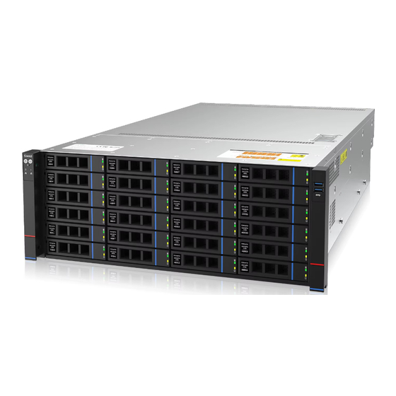
1.1 Product Overview SL401-G4 Series 4U Dual-socket Rack-Mount Server is a new generation of versatile 4U dual-socket rack-mount servers launched by Gooxi to meet the needs of the Internet, IDC (Internet Data Center), cloud computing, big data, enterprise markets, and telecom business applications. It is suitable for core IT operations, cloud... -
Page 7: Product Structure
Rear view 1-2 1.2 Product Structure Eagle Stream 4U Dual-Socket Rack-Mount Server Exploded View Structure diagram 1-3 Name Name Front Hard Drive Memory Stick Rear Hard Drive Fan Bracket Hard Drive Bracket Module Top Cover Front Hard Drive Backplane PCIe Module Air Duct Module 2.5-inch Hard Drive Module Fan Module... -
Page 8: Logical Structure
1.3 Logical Structure The logic of the SL401-G4 Series Dual-Socket Rack-Mount Server is as shown in the following diagram: Motherboard logic block diagram 1-4 The CPU adopts the 4th/5th generation Intel Xeon Scalable processor, LGA4677 socket. Each CPU supports 8 channels, and each channel supports 2 DDR5 ... -
Page 9: Product Specifications
1.4 Product Specifications Product Series SL401-G4 Form Factor 830x444x176.5mm (D*W*H) System Size Supports 1 or 2 4th/5th generation Intel® Xeon® Scalable processors, TDP Processor 350W Memory 32 DDR5 memory slots, supporting DDR5 RDIMM 4400/4800/5600 MHz Internal Storage 3 MiniSAS HD interfaces, 2 SATA M.2 SSD interfaces (22110/2280 specifications) Interface External Hard... -
Page 10: Hardware Description
2. Hardware Description 2.1 Front Panel 2.1.1 Appearance 36x2.5-inch hard drive configuration Figure 2-1 Name Name Switch Panel VGA interface 3.5-inch hard drive USB3.1 interface Table 2-1 2.1.2 Indicator lights and buttons Figure 2-2... - Page 11 Indicator/Button Indicator/Button GOOXI Logo Hard Drive Activity Indicator Power Switch System Alarm Indicator Button/Indicator UID Button/Indicator OCP1 Network Card Presence Indicator Reset Server Button OCP2 Network Card Presence Indicator LED status description Indicator Logo Status description light/button Gooxi logo Description of the power indicator light: Green (steady on): Indicates that the device has been powered on normally.
-
Page 12: Interface
Corresponding to the OCP2 network card connection status indicator light. OCP2 network Green (steady on): Indicates that the OCP2 network card presence card is in place. status indicator Off: Indicates that the OCP network card is not light installed or is malfunctioning. Note: This corresponds to the two OCP network cards on the motherboard. -
Page 13: Indicator Lights And Buttons
Figure 2-4 Name Name Riser1 module Riser2 module Riser3 module Riser4 module OCP1 network card slot BMC module OCP2 network card slot Power module 1 Power module 2 Rear hard drive Table 2-5 Note: 1. Riser1/Riser2/Riser3/Riser4 can be selected for either the rear hard drive ... -
Page 14: Interface
Table 2-6 Description of Power Module Indicators Indicator Status description light/button Green (steady on): Indicates that the input and output are normal. Orange (steady on): Indicates that the AC power cord is unplugged or the power module is missing, and only one parallel-connected power module has AC input;... -
Page 15: Memory
For specific optional system configurations, please consult Gooxi sales. Processor positions are as shown in the following diagram: Figure 2-7 2.4 Memory 2.4.1 Memory slot location This motherboard adopts the Intel Eagle Stream platform. Each CPU supports 8 channels, and each channel supports 2 DDR5 memories. -
Page 16: Storage
The server can install up to 32 DDR5 memories and supports DDR5 RDIMM server memory. The memory frequency supports 4400/4800MHz. The memory installation principles must be followed when configuring the memory (CPU1 is the same as CPU0). Figure 2-9 Note: 1. -
Page 17: Hard Drive Serial Number
2.5.2 Hard drive serial number Front 24x3.5-inch hard drive configuration Figure 2-10 Rear 12x3.5-inch hard drive configuration Figure 2-11 2.5.3 Hard drive status indicator Figure 2-12 Hard drive status indicator description Function Act LED Status LED Fault LED Hard drive in Steady on place... -
Page 18: Power Supply
For power modules configured in the same server, the power module models must be identical; For specific optional system accessories, please consult Gooxi sales. The power supply positions are as shown in the following diagram: Figure 2-13 2.7 Fans... -
Page 19: I/O Expansion
Figure 2-14 2.8 I/O Expansion 2.8.1 PCIe slot location Figure 2-15 The slots provided by Riser1 module are Slot0, Slot1, Slot2. When using a PCIe expansion module with 2 slots, Slot1 is not available. The slots provided by Riser2 module are Slot3, Slot4, Slot5. When using a ... -
Page 20: Pcie Slot Description
2.8.2 PCIe slot description When CPU1 is not in place, its corresponding PCIe slot is unavailable. Subordinate PCIe slot PCIe standard Bus bandwidth Slot size OCP1 CPU0 PCIe 5.0 OCP2 CPU1 PCIe 5.0 Full-Height Slot 0 CPU0 PCIe 5.0 X8 or X16 Full-Length Full-Height Slot 1... - Page 21 Figure 2-16 PCIE Expansion Module 2 x32 to x16+x8+x8 adapter card – Installed in Riser1 position, providing PCIe slots as Slot0, Slot1, and Slot2 – Installed in Riser2 position, providing PCIe slots as Slot3, Slot4, and Slot5 Figure 2-17 PCIe Expansion Module 3 ...
-
Page 22: Pcba
Figure 2-19 2.5-inch hard drive module Figure 2-20 2.9 PCBA 2.9.1 Motherboard... - Page 23 Motherboard Figure 2-21 Name Name CPU0 DDR5 Memory Channels 1,2,3,4 CPU0 DIMMA1/A0/B1/B0/C1/C0/D1/D0 connectors CPU0 DDR5 Memory Channels 8,7,6,5 CPU0 DIMMH0/H1/G0/G1/F0/F1/E0/E1 connectors CPU1 DDR5 Memory Channels 1,2,3,4 CPU1 DIMMA1/A0/B1/B0/C1/C0/D1/D0 connectors CPU1 DDR5 Memory Channels 8,7,6,5 CPU1 DIMMH0/H1/G0/G1/F0/F1/E0/E1 connectors 2 hard drive backplane I2C connectors, 2 MCIO I2C MCIO x8 connectors(CPU1) ×...
-
Page 24: Hard Drive Backplane
Connector Rear Window Hard Drive (2 2*6+4Pin High-power GPU drives) Backplane Power Connector Connector Table 2-12 2.9.2 Hard drive backplane 24×3.5-inch Backplane TOP surface Figure 2-22 Description Function 29-pin SATA/SAS hard supports SAS/SATA 3.0 hard drive drive connector interface for connecting HDD/SSD Table 2-13 Bottom surface Figure 2-23... - Page 25 Temperature-controlled fan used for 4-pin fan interface socket provides SAS/SATA x4 interface SFF-8639 MiniSAS for connecting PCH or connector HBA/RAID Card Table 2-14 Rear 12×3.5-inch Backplane TOP surface Figure 2-24 Description Function 29-pin SATA/SAS hard supports SAS/SATA 3.0 hard drive drive connector interface for connecting HDD/SSD Table 2-15...
-
Page 26: Installation Instructions
3. Installation Instructions 3.1 Chassis Top Cover Installation Step 1: Lift the slot at the opening position, push and lift it in the direction indicated by the diagram. Figure 3-1 3.2 Installation of Accessories 3.2.1 CPU installation Step 1: Align the triangular mark on the CPU with the handle on the bracket as ... -
Page 27: Heatsink Installation
3.2.2 Heatsink installation Step 1: Remove the protective cover on the motherboard CPU socket. Step 2: Install the CPU and heatsink onto the CPU socket. (As shown in the diagram below) Figure 3-3 Step 3: Press down on the four corners of the heatsink's fixing lock towards ... -
Page 28: Bbu Installation
CPU0 DIMMB0/B1,DIMMA0/A1, DIMMD0/D1, DIMMC0/C1, DIMMG1/G0, DIMMH1/H0, DIMME1/E0, DIMMF1/F0. The 16 memory slots controlled by CPU1 are as follows: CPU1 DIMMB0/B1,DIMMA0/A1,DIMMD0/D1,DIMMC0/C1, DIMMG1/G0, DIMMH1/H0, DIMME1/E0, DIMMF1/F0. Please note that the memory notches should match the DIMM slots' notches. Insert each DIMM module vertically to prevent incorrect installation. -
Page 29: Server Slide Rail Installation
Step 1: Attach the Velcro to the air duct. Step 2: Secure the BBU to the air duct using the Velcro. 3.2.5 Server slide rail installation Step 1: Prepare two slide rails and pull out the inner rail. ... - Page 30 Figure 3-10 Note: When installing the guide rail, align it with the U-mark, and push it into place until you hear a click sound. Secure it firmly using M5 screws. Step 4: Align the chassis with the inner rails installed with the outer rails for ...
- Page 31 Figure 3-12 Note: During equipment maintenance, it is necessary to loosen the panel screws and pull the chassis lightly. Do not push or pull the chassis at random speed to avoid damage to the equipment.
-
Page 32: Configuration Instructions
4. Configuration Instructions 4.1 Initial Configuration 4.1.1 Power on and start Before powering on, it is necessary to ensure that all configurations of the server are installed in accordance with the corresponding specifications and standards, and keep the server turned off but not unplugged from the power supply. - Page 33 Figure 4-1 PCH state after G3 PCH state setting after G3, the menu options are: S0: Power on and start up directly S5: You need to press the Power button to turn on the power leave power state unchanged: Leave the power state unchanged . Default: S0 Log in to the iBMC management interface to perform remote power-on and ...
-
Page 34: Initial Data
Figure 4-2 For detailed usage of BMC and BIOS, please refer to the corresponding user manual. 4.1.2 Initial data BMC default account: admin BMC default password: Gooxi@123. BMC default address: 192.168.100.1 BIOS Default Password: N/A 4.1.3 Configure BIOS Press the <DEL>... -
Page 35: Configure Bmc
Figure 4-3 The Main interface contains the basic information of the BIOS system, such as the BIOS version number, CPU model, memory capacity, and the system time can be set. For detailed instructions, please refer to the "BIOS User Manual". Navigation key description: ... - Page 36 After the server is powered on, turn it on. Pay attention to the POST process when starting the server. In the lower left corner of the logo screen, the IP address is displayed. After the server powers on, pay attention to the POST process. Press the ...
- Page 37 When the "Configuration Address Source" option is set to "Unspecified," it will display the network parameters (IPv4) for the system's shared Ethernet port. The displayed information includes the current IP configuration method, BMC IP, subnet mask, MAC address, router IP, and router MAC. BMC Dedicated Management Channel ...
- Page 38 will display the network parameters (IPv6) for the system's shared Ethernet port. BMC Dedicated Management Channel IPV6 Support Choose whether to support IPV6, the menu options are: Enabeld: support IPV6 Disabled: does not support IPV6 Default: Enabeld When changing from "Unspecified"...
- Page 39 Figure 4-6 This page sets the IP address of the BMC management network port.
-
Page 40: Appendix
If the above steps do not resolve the issue, try replacing the monitor with a known working one to confirm if the original monitor is faulty. If the issue persists, please contact Gooxi's customer service department for resolution. Front Panel Indicator Lights Alarm Refer to the instructions in the manual to determine the specific alarm information indicated by the front panel lights and buttons. - Page 41 Set static or dynamic IP and ensure ping connectivity. If the web interface does not open, try using a newer version of Internet Explorer. If the problem is not resolved, please contact Gooxi’s customer service department for further assistance and resolution.
-
Page 42: Scrap Recycling
6. Scrap Recycling For environmental protection and resource reuse, we earnestly ask you to properly handle discarded server products. Before discarding the server, we recommend that you completely demagnetize the storage media, clear data, and physically destroy them to ensure that your personal data is not leaked.
Need help?
Do you have a question about the SL401-G4 Series and is the answer not in the manual?
Questions and answers