
Related Manuals for Gooxi SR201-G2


Summary of Contents for Gooxi SR201-G2
- Page 1 SR201-G2 2U Rackmount Server User Manual Document version:01 Release date:2023/12/25 Shenzhen Gooxi Information Security Co. , Ltd.
-
Page 2: Statement
Statement Copyright Statement © Shenz hen Gooxi Inf orma ti on Se curi t y Co., Lt d. All rights reserved. This user manual, including but not limited to all information contained herein, is protected by copyright law. Without the permission of Shenzhen Gooxi Information Security Co., Ltd. -
Page 3: Foreword
Foreword This manual is the product technical manual for the SR201-G2 2U rack-mounted server, primarily providing an introduction and explanation of the product's appearance, structure, hardware installation, and basic configurations. This manual is intended for reference and research by professional technical personnel. The installation and maintenance of this product should be carried out only by experienced technical personnel. -
Page 4: Table Of Contents
Contents Statement.............................. 1 Foreword...............................2 ........................5 1.1 Product overview........................5 1.2 Product structure........................7 1.3 Logical structure........................8 1.4 Product specifications....................... 9 ......................... 10 2.1 Front panel..........................10 2.1.1 Appearance........................ 10 2.1.2 Indicator lights and buttons ..................11 2.1.3 Interface........................12 2.2 Rear panel ..........................13 2.2.1 Appearance........................ - Page 5 3.2.2 Installation of heatsink .....................30 3.2.3 Installation of memory ..................... 31 3.2.4 Installation of server slide rail ................31 ......................34 4.1 Initial configuration ......................34 4.1.1 Power on the system ....................34 4.1.2 Initial data .........................35 4.1.3 Configuration of BIOS .................... 35 4.1.4 Configuration of BMC ....................36 Appendix.............................40...
-
Page 6: Product Overview
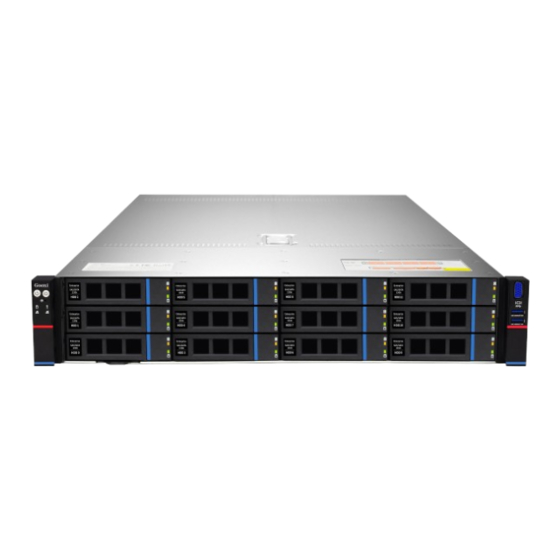
1.1 Product overview The SR201-G2 2U rack-mounted server is a versatile dual-socket server introduced by Gooxi based on the AMD Genoa platform. It is designed to meet the demands of various applications, including the internet, IDC (Internet Data Center), cloud computing, enterprise markets, and telecommunications services. - Page 7 ② SR201-D12RE-G2 (Figure 1-2) ③ SR201-D25RE-G2 (Figure 1-3) 11 PCIe expansion rear window (Figure1-4)
-
Page 8: Product Structure
1.2 Product structure The physical structure of the SR201-G2 2U rack-mounted server may vary depending on specific requirements. Taking the SR201-D12RE-G2 model as an example, the various components of the server are described as shown in the following figure: Structure Diagram (1-5) -
Page 9: Logical Structure
1.3 Logical structure The logic of the SR201-G2 2U rack server is as shown in the following diagram: Motherboard logic block diagram ( 1-6) 2 SP5 Sockets, supporting 2 AMD EPYC™ 9004 series processors. A single CPU supports 12 DDR5 channels, and two CPUs together support 24 DIMM DDR5 ... -
Page 10: Product Specifications
1.4 Product specifications SR201-D08R-G2 SR201-D12R-G2 SR201-D08R-NV-G2 SR201-D12RE-G2 System Model SR201-D25RE-G2 SR201-D12R-NV-G2 Gooxi 2U rackmount server Chassis Motherboard G2DLRO-B Supports 2 AMD EPYC™ 9004 processors Supports DDR5-4800/4400MHz RDIMM/LRDIMM memory; Memory supports a single capacity of 8G/16GB/32GB/64GB/128GB/256GB, and the entire machine supports a maximum memory capacity of 6TB. -
Page 11: Front Panel
2.1 Front panel 2.1.1 Appearance 8x3.5 inch hard drive configuration Figure (2-1) Name Name DVD drive (optional) USB3.0 interface VGA interface 3.5 inch hard drive table (2-1) 12x3.5 inch hard drive configuration Figure (2-2) Name Name 3.5 inch hard drive USB 3.0 interface VGA interface table (2-2) -
Page 12: Indicator Lights And Buttons
2.1.2 Indicator lights and buttons Figure ( 2-4) Indicator light /button Indicator light /button Gooxi logo Hard drive indicator Power switch System Alarm Indicator button/indicator UID button/indicator Network port 1 connection status indicator Restart button Network port 2 connection status... -
Page 13: Interface
System warning indicator. Including system alarms, System warning fan alarms, power supply alarms, etc., which can be indicator viewed through the IPMI management software. The Ethernet port indicator lights correspond to the network card slots. Green (steady on): indicates that the network port is Network port connected normally. -
Page 14: Rear Panel
2.2 Rear panel 2.2.1 Appearance Appearance of the rear panel Figure ( 2-6) Name Name Riser1 module Riser2 module Riser3 module Riser4 module OCP 3.0 network card (optional) PSU1 PSU2 Table (2-7) Note: 1. Riser1 module, Riser2 module, Riser3 module, Riser4 module can be optionally equipped with either rear-mounted hard drive module or PCIe riser module. -
Page 15: Interface
When configuring with a single processor, it must be installed in the CPU 0 socket If configuring processors in the same server, they must have the same model For specific available system options, please consult Gooxi sales Processor positions as shown in the diagram below:... -
Page 16: Memory
Figure (2-9) 2.4 Memory 2.4.1 Memory slot location The motherboard supports 12 DDR5 channels, and 2 CPUs support a total of 24 DDR5 inserted memory slots Figure (2-10) -
Page 17: Memory Compatibility Information
2.4.2 Memory compatibility information The motherboard supports DDR5 RDIMM/LRDIMM server memory, and the memory frequency supports 4800/5200MHz. Note: The same server must use the same type of DDR5 memory, and all of the memory must run at the same speed, with the speed value being the lowest of the following: Memory speed supported by a specific CPU. -
Page 18: Hard Drive Sequence Number
Configuration 2 Front hard drive Riser1/2 module supports NVMe hard drives 8x3.5-inch hard supports eight 3.5- expansion of four 3.5-inch require a Retimer drive inch or 2.5-inch SAS/SATA hard drives. card. SAS hard SAS/SATA/NVMe Riser3/4 module supports the drives require an hard drive expansion of four 2.5-inch optional SAS pass-... -
Page 19: Hard Drive Status Indicator
12x3.5 -inch hard drive configuration Figure ( 2-12) 25x2.5 -inch hard drive configuration Figure ( 2-13) 2.5.3 Hard drive status indicator Figure ( 2-14) Hard drive status indicator description Function Fault LED Act LED Status LED Hard drive in always on position Hard drive always on... -
Page 20: Power Supply
When configuring 2 power modules, it supports 1+1 redundancy For the server's power modules, the power module models must be the same For specific optional system components available for purchase, please consult Gooxi sales The power supply location is shown in the figure below: Figure (2-15)... -
Page 21: I/O Expansion
2.7 I/O expansion 2.7.1 PCIe slot distribution Figure (2-17) Riser 1 provides slots slot 0-2. Riser 2 provides slots Slot3-5. Riser3 provides slots Slot6- 7. Riser4 provides slots Slot8-9 (Riser modules support optional adapter cards 4.0/5.0). When selecting the PCIe expansion module, Slot0 can accommodate either a PCIe X8 or PCIe X16 device, Slot1 can accommodate a PCIe X8 device, and Slot2 can accommodate a PCIe X16 device. -
Page 22: Pcie Slot Description
2.7.2 PCIe slot description PCIe slot Secondary Slot size PCIe standard Bus bandwidth Onboard PCIe x2 2*RJ45 CPU0 Network (2.0) Card CPU0 1*OCP3.0 PCIe5.0 x8 Network Card 2 * PCIe5.0 X16 slot full height full length Riser1 CPU0 PCIe5.0 x32 1 *( PCIe5.0 X16 slot, full height full length 2 * PCIe5.0 X8 slot... - Page 23 PCIE adapter card 2:748-PCIEIB2-X16X16 – Installed in Riser1/2 position, providing 2 PCIe5.0 X16 Figure (2-19) PCIE adapter card 3: M2U748-PCIEIB3-X16 – Installed in Riser3 position, providing 1 PCIe5.0 X16 slot Figure (2-20) 3.5-inch hard drive module – Supports in Riser1/2 positions, a single module providing 2 slots for 3.5- inch hard drives Figure (2-22)
-
Page 24: Pcba
2 .5-inch hard drive module – Installed in Riser3/4 positions, a single module provides 2 slots for 2.5- inch SATA or NVMe hard drives Figure (2-23) 2.8 PCBA 2.8.1 Motherboard G2DLRO-B motherboard diagram (2-24) -
Page 25: Hard Drive Backplane
Name Name 2U chassis fan control 6pin BMC_OCP2 interface 4U chassis fan control 4pin 8643 interface interface Memory slot (corresponding to OCP3.0 CPU0) CPU0 BP HDD LED Riser1 MCIO interface Riser3 MCIO interface BP Power 2*4 pin interface Slimline PCIE4.0 X8 BP Power 2*4 pin interface BMC_OCP1 CPU1... - Page 26 Description Function Backplane power 1, 2 ATX power input transmission connector for 12V power transmission For 4pin fan interface 3, 4, 5, 6 Temperature controlled fan socket For transmission of 12Gb/s 7, 8 MiniSAS HD High Speed SAS or 6Gb/s SATA signals Connector Table (2-15) 12×3.5-inch backplane...
- Page 27 25×2.5-inch backplane Top surface Figure (2-29) Description Function 1. Supports 12Gb/s SAS hard drives. 2.Supports 6Gb/s SATA hard drives. SAS/SATA hard drive connector 3.Supports hot-swappable SAS/SATA hard drives. Table (2-18) Bottom surface Figure (2-30) Description Function Power Connector Backplane Power Transmission Connector for 12V Power Transfer MiniSAS HD High-Speed Connector Used for the Transmission of 12Gb/s...
- Page 28 2×2.5 Rear Hard Drive Backplate - 1 Top surface Figure (2-31) Description Function 1.Supports 12Gb/s SAS Hard Drives SAS/SATA hard drive connector 2.Supports 6Gb/s SATA Hard Drives Table (2-20) Bottom surface Figure (2-32) Description Function 7PIN SATA interface SATA Disk Signal Cable Interface 1、5 Temperature Sensor IC Temperature Sensor Chip...
-
Page 29: Chassis Top Cover Installation
3.1 Chassis top cover installation Step 1: Align the top cover hooks with the openings on the chassis and place it downwards Step 2: Push it forward in the direction of the arrow until it locks into place Figure (3-1) 3.2 Installation of accessories 3.2.1 Installation of CPU Before starting the CPU installation, please read the following guidelines:... - Page 30 Figure (3-2) Figure (3-3) Figure (3-4)
-
Page 31: Installation Of Heatsink
3.2.2 Installation of heatsink Before starting to install the heatsink, please read the following guidelines: ⚫ Before installing the heatsink, please be sure to turn off the computer and unplug the power cord from the power outlet to prevent damage to the hardware. ⚫... -
Page 32: Installation Of Memory
3.2.3 Installation of memory The 12 memory slots controlled by CPU 0/CPU 1 on the motherboard are as follows: DIMM_A,DIMM_B,DIMM_C,DIMM_D,DIMM_E,DIMM_F,DIMM_G,DIMM_H,DIMM_I, DIMM_J, DIMM_K, DIMM_L. It's important to note that the notch on the memory module should align with the notch on the DIMM slot. - Page 33 Figure (3-9) Step 2: Fix the inner rails on both sides of the chassis. Figure (3-10) Step 3: Install the outer rail on the cabinet bracket and secure the screws. Figure (3-11)
- Page 34 Note: When installing the guide rails, align them with the "U" mark. Once you hear a clicking sound, it's securely in place. Fasten it with M5 screws. Step 4: Align the chassis with the inner rails installed with the outer rails for installation.
-
Page 35: Initial Configuration
4.1 Initial configuration 4.1.1 Power on the system Before powering on, ensure that all server configurations are installed according to the corresponding specifications and standards, and the server is powered off but remains connected to the power source. Additionally, ensure that all cables are properly connected, and the power supply voltage matches the requirements of the equipment. -
Page 36: Initial Data
AC Loss Control Power-On Settings Status settings, menu options are: Always off: Power on directly when power is restored Always on:Power-on requires pressing the Power button to start Previous:Keep the power state unchanged You can access the iBMC management interface to remotely control power operations. -
Page 37: Configuration Of Bmc
Figure (4-3) The Main interface contains basic information about the BIOS system, such as the BIOS version number, CPU model, and memory capacity. It also allows you to set the system time. For detailed instructions, please refer to the 'BIOS User Manual'. ... - Page 38 Figure (4-4) After entering the account and password, you can access the homepage. You can set the BMC IP address in the management interface. On the left side of the interface, switch to 'Settings' -> 'Network Settings' -> 'Network IP Settings' as shown in the following image: Figure (4-5) In the powered-on state of the server, ensure that the dedicated management network cable for BMC is connected properly.
- Page 39 Figure (4-6) Configure IPV4 support BMC sharelink Management Channel Configuration Address Source: Configure BMC IP address allocation mode. The menu options are: Unspecified:Do not change the BMC parameters(default) Static: BIOS static IP setting DynamicBmcDhcp: BMC is running DHCP for dynamic IP allocation. DynamicBmcNonDhcp: BMC is running a Non-DHCP protocol for dynamic IP allocation.
- Page 40 interface. This includes the current IP configuration method, BMC IP, subnet mask, MAC address, route IP, and route MAC.
-
Page 41: Appendix
If the above steps do not resolve the issue, try replacing the monitor with a known working one to confirm if the original monitor is faulty. If the issue persists, please contact Gooxi technical support for further assistance. Front Panel Indicator Lights Alarm Refer to the instructions in the manual to determine the specific alarm information indicated by the front panel lights and buttons. - Page 42 IPMI connection is not effective, check the network environment. Set static or dynamic IP and ensure ping connectivity. If the web interface does not open, try using a newer version of Internet Explorer. If the problem is not resolved, please contact Gooxi technical support for further assistance.
Need help?
Do you have a question about the SR201-G2 and is the answer not in the manual?
Questions and answers