
Related Manuals for Gooxi SL401-G3


Summary of Contents for Gooxi SL401-G3
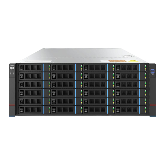
- Page 1 SL401-G3 Rackmount Server User Manual Document version: 01 Release date: 2023/02/09 Shenzhen Gooxi Information Security Co., Ltd.
-
Page 2: Statement
Gooxi provides this user manual "as is" and to the extent permitted by law, makes no express or implied warranties or guarantees, including but not limited to merchantability, fitness for a particular purpose, non-infringement of any rights of others, and any warranties or guarantees regarding the use or inability to use this user manual. -
Page 3: Foreword
Foreword This manual is the product technical manual for the Gooxi Whitely platform 4U model servers. It primarily provides an introduction and explanation of the product's appearance, structure, hardware installation, and basic configuration. Please note that this manual is intended for reference and research purposes for professional technical personnel. -
Page 4: Table Of Contents
Contents Statement............................. 1 Foreword..............................2 1. Product Introduction ........................5 1.2 Product Structure ........................7 1.3 Logical Structure ........................7 1.4 Product Specifications ......................9 2. Hardware Description ........................10 2.1 Front Panel ..........................10 2.1.1 Appearance ......................10 2.1.2 Indicator lights and buttons ................. 11 2.1.3 Interface ......................... - Page 5 2.9.2 Hard drive backplane ....................26 3. Installation Instructions ........................ 30 3.1 Chassis Top Cover Installation ..................30 3.2 Installation of Accessories ....................30 3.2.1 CPU installation ....................30 3.2.2 Heatsink installation ..................... 31 3.2.3 Memory installation ....................31 3.2.4 Server slide rail installation ................. 33 4.
-
Page 6: Product Introduction
1.1 Product Overview SL401 Whitely 4U dual-socket rackmount server is a new generation 4U dual-socket rack server launched by Gooxi to meet the diverse needs of the Internet, IDC (Internet Data Center), cloud computing, enterprise markets, and telecommunications services. It... - Page 7 Rear view of 24-bay configuration 1-2 Rear view of 36-bay configuration 1-3...
-
Page 8: Product Structure
1.2 Product Structure Product exploded view of SL401 Whitely 4U dual-socket rack server (example of 36-bay model) Structure diagram 1-3 Name Name Front hard drive Rear backplane assembly Air duct Rear hard drive Front backplane assembly Full height PC IE module Fan module Half height PCIE module Memory module... - Page 9 Motherboard logic block diagram 1-4 The CPU uses the third generation Intel® Xeon® Scalable processor, LGA 4189 socket, TDP power consumption 270W. Each CPU supports 8 channels of DDR4, and each channel supports 2 memory modules, RDIMM/LRDIMM. Two CPUs support a maximum capacity of 12 TB (including Optane memory).
-
Page 10: Product Specifications
1.4 Product Specifications Product Series SL401-D24RE SL401-D36RE 4U24 bay 4U36 bay Product Type System Size 798 *433.4* 176.5 mm (depth*width*height) Processor Supports 1 or 2 3rd generation Intel® Xeon® Scalable series processors DDR4 memory slots, supporting DDR4 LRDIMM/RDIMM2666 /2933/3200 MHz; the maximum capacity of a single slot is 256GB, Memory compatible with Optane memory, and the entire machine supports a maximum memory capacity of 12 TB... -
Page 11: Hardware Description
2. Hardware Description 2.1 Front Panel 2.1.1 Appearance 24x3.5 -inch hard drive configuration Figure 2-1 Name Name Left ear assembly Right ear assembly 3.5-inch hard drive Table 2-1 36 x3.5-inch hard drive configuration Figure 2-2... -
Page 12: Indicator Lights And Buttons
Name Name Left ear assembly Front 3.5-inch hard drive VGA interface Rear 3.5-inch hard drive Table 2-2 2.1.2 Indicator lights and buttons Figure 2-4 Indicator light/button Indicator light/button Power switch System alarm indicator light button/indicator light UID button/light Network port 1 connection status indicator light Hard drive indicator light Network port 2 connection... -
Page 13: Interface
of this button powers on the server. Button/Indicator Light used conveniently locating the server to be operated. It can be turned on or off manually by pressing the UID button or remotely controlled via BMC command. UID Indicator Light Explanation: button/light Blue (Solid/Blinking): Indicates the server is located. -
Page 14: Rear Panel
Figure 2-5 Name USB3.0 interface Table 2-5 Interface Description Quantity Name Type Description USB 3.0 For connecting USB devices interface Table 2-6 2.2 Rear Panel 2.2.1 Appearance Rear panel appearance Figure 2-6 Name Name Riser1 module Riser2 module Riser3 module Riser4 module... -
Page 15: Indicator Lights And Buttons
Network OCP network card slot port+VGA+USB Power module 1 Power module 2 Table 2-7 Note: 1. Riser1 module, Riser2 module, Riser3 module, and Riser4 module can be optionally equipped with rear hard drive modules or PCIe riser modules. 2. This picture is for reference only. The actual configuration shall prevail. ... -
Page 16: Interface
upgrade process. Yellow (1Hz/Blinking): Indicates a continuous power warning event; power supply over-temperature protection, power output over-current/over-voltage, slow fan speed. Off: Indicates no AC power input. Table 2-9 2.2.3 Interface Rear panel interface Figure 2-8 Name Name Management network port VGA interface Gigabit network... -
Page 17: Processor
Processors configured on the same server must be of the same model. For specific optional system configurations available for purchase, please consult with Gooxi sales. The location of the processor is as shown below: Figure 2-9... -
Page 18: Memory
2.4 Memory 2.4.1 Memory slot location This motherboard utilizes the Intel Whitely platform, paired with Intel Xeon ICE Lake CPUs. Each CPU supports 8 channels, with 2 DIMMs per channel. The motherboard can support 32 DIMMs in total. When only one DIMM is inserted, it should be prioritized to be inserted into the slot highlighted in blue on the diagram (the plastic color of the slot on the slot board is blue). -
Page 19: Storage
2.5 Storage 2.5.1 Hard drive configuration Maximum number of Maximum number of rear hard Configuration Description front hard drives (pcs) drives (pcs) Riser1 module (2x3.5 / 2.5) * 2 -Only supports SAS/SATA hard drives Riser2 module (2x3.5 / 2.5) * 2 Front hard drive (24 24x3.5-inch -Only supports SAS/SATA hard... -
Page 20: Hard Drive Status Indicator
Front 24-bay figure 2-12 Rear 12-bay figure 2-13 2.5.3 Hard drive status indicator Figure 2-14 Hard drive status indicator light description Function Act LED Status LED Fault LED Hard drive in Steady on place hard drive Flashing activity 4Hz/second Hard drive Flashing Steady on... -
Page 21: Power Supply
For power modules configured on the same server, the power module models must be the same. For specific optional system options, please consult Gooxi sales. The power supply location is shown in the figure below: Figure 2-15 2.7 Fans... -
Page 22: I/O Expansion
Figure 2-16 2.8 I/O Expansion 2.8.1 PCIe slot location Figure 2-17 The slots provided by the Riser1 module are Slot 0, Slot 1, and Slot 2. When using a 2-slot PCIE expansion module, Slot 1 is unavailable. The slots provided by the Riser2 module are Slot 3, Slot 4, and Slot 5. When ... -
Page 23: Pcie Expansion Module
network CPU0 PCIe 4.0 _ card Slot 0 CPU0 PCIe 4.0 _ full height full length Slot 1 CPU0 PCIe 4.0 _ Full height and half length Slot 2 CPU0 PCIe 4.0 _ Full height and half length Slot 3 CPU1 PCIe 4.0 _ full height full length... - Page 24 Figure 2-19 PCIE expansion module 3 x16 to x8 (x16 slot) +x8 adapter card Figure 2-20 PCIE expansion module 4 Figure 2-21 3.5-inch hard drive module Figure 2-22 2.5-inch hard drive module ...
-
Page 25: Pcba
Figure 2-23 2.9 PCBA 2.9.1 Motherboard Motherboard Figure 2-21 Name BMC_UART5, BMC debugging serial port Used for CPU0 VR upgrade and burning, no jumper cap is connected by default Used for CPU1 VR upgrade and burning, no jumper cap is connected... - Page 26 by default Front VGA bracket connector Front USB 3.0 connectors (x2) Built-in USB3.0 connector Rear USB3.0 connector q(x2) Trusted Platform Module (TPM) M.2 PCIE X2 CONN, only supports PCIe Only 2280 size SSD1/SSD2 specification CPLD JTAG Header, used to burn CPLD programs Front panel buttons, LED connector 2X10 BP HDD LED Connector (for Rear HDD BP backplane) sSATA, SATA 3.0 Connection from PCH (8643 miniSAS HD with...
-
Page 27: Hard Drive Backplane
PEHP CPU1 (1.8V CPU I2C Reserved for U.2 hard drive backplane) J49/J50 CRPS Slots SKU IDs (Reserved) J7/J8/J9/J10 BP1~BP4 BMC I2C Connector (Reserved for HDD BP backplane) 1X2 CD/DVD Power Connector NVME Key (VROC) VR Debug Mode Jump (Reserved for RD test Only) CPLD No CPU Power ON Jump (Reserved for RD test Only) 2X4 SATA sGPIO Header (for 8643 miniSAS HD Conn J29/J31) 2X4 sSATA sGPIO Header (for 8643 miniSAS HD Conn J28) - Page 28 Description Function 1. Supports up to 12G/b SAS hard drive. SAS/SATA hard drive 2. Supports up to 6G/b SATA hard connector drive. 3. Supports SAS/SATA hard drive hot swap. Table 2-14 Bottom surface Figure 2-23 Description Function Backplane power transmission ATX power input connector, used for 12V power transmission...
- Page 29 connector 2. Supports up to 6G/b SATA hard drive. 3. Supports SAS/SATA hard drive hot swap. Table 2-16 Bottom surface Figure 2-25 Description Function Temperature controlled fan 1, 2, 3, 4 For 4pin fan interface socket MINI SAS HD High Speed For transmission of 12G/b SAS or Connector 6G/b SATA signals...
- Page 30 Figure 2-29 Description Function 1, 5 7PIN SATA interface SATA disk signal cable interface Temperature sensor IC temperature sensor chip Used hard drive SGPIO lighting signal positioning lighting and fault LED indication functions. I2C interface For I2C signal interface Backplane power transmission Power interface...
-
Page 31: Installation Instructions
3. Installation Instructions 3.1 Chassis Top Cover Installation Step 1: Align the hooks on the top cover with the openings on the chassis, and place it downwards. Step 2: Rotate the top cover lock latch in the direction of the arrow until it ... -
Page 32: Heatsink Installation
Figure 3-3 3.2.2 Heatsink installation Step 1: Remove the processor idle bracket. (As shown in the figure below) Figure 3-4 Step 2: Align the heatsink with the heatsink mounting screws on the CPU socket, and tighten the heatsink mounting screws in the indicated sequence. (As shown in the figure below) Figure 3-5 Caution: The pins on the motherboard are very fragile and can be easily... - Page 33 DIMMB0/B1, DIMMA0/A1, DIMMD0/D1, DIMMC0/C1, DIMMG1/G0, DIMMH1/H0, DIMME1/E0, DIMMF1/F0. It is important to note that the notch on the memory module should align with the notch on the DIMM slot. Insert each DIMM module vertically to prevent incorrect installation. Figure 3-6 Figure 3-7 Note: Please use memory modules with the same CAS delay value on this motherboard.
-
Page 34: Server Slide Rail Installation
3.2.4 Server slide rail installation Step 1: Prepare two slide rails and pull out the inner rail Figure 3-8 Step 2: Fasten the inner rails to both sides of the chassis Figure 3-9 Step 3: Install the outer rails on the cabinet brackets and secure the screws ... - Page 35 Step 4: Align the chassis with the outer rail and proceed with the installation Figure 3-11 Note: When pushing the chassis forward, you will hear a snapping sound. When the chassis cannot be pushed further, you need to pull the inner rail buckle downward before you can continue to push the chassis gently.
-
Page 36: Configuration Instructions
4. Configuration Instructions 4.1 Initial Configuration 4.1.1 Power on and start Before powering on, it is necessary to ensure that all configurations of the server are installed in accordance with the corresponding specifications and standards, and keep the server turned off but not unplugged from the power supply. - Page 37 Figure 4-1 PCH state after G3 PCH state setting after G3, the menu options are: S0: Power on and start up directly. S5: You need to press the Power button to turn on the power. leave power state unchanged: Leave the power state unchanged. Default: S0 Log in to the iBMC management interface to perform remote power-on and ...
-
Page 38: Initial Data
Figure 4-2 For detailed usage of BMC and BIOS, please view the corresponding user manual. 4.1.2 Initial data BMC default account: admin BMC default password: Gooxi@123. BMC default address: 192.168.100.1 BIOS Default Password: None 4.1.3 Configure BIOS Press the <DEL>... -
Page 39: Configure Bmc
Figure 4-3 The Main interface contains the basic information of the BIOS system, such as the BIOS version number, CPU model, memory capacity, and the system time can be set. For detailed instructions, please refer to the "BIOS User Manual". Navigation key description: ... - Page 40 when starting the server. In the lower left corner of the logo screen, the IP address is displayed. After the server powers on, pay attention to the POST process. Press the <DEL> or <ESC> key on the keyboard to enter the BIOS Setup interface. Switch to the following interface: Figure 4-4 Configure IPV4 support :...
- Page 41 port. The displayed information includes the current IP configuration method, BMC IP, subnet mask, MAC address, router IP, and router MAC. BMC Dedicated Management Channel Configuration Address source Configure the BMC IP address allocation mode, the menu options are: ...
- Page 42 BMC Dedicated Management Channel IPV6 Support Choose whether to support IPV6, the menu options are: Enabeld: support IPV6 Disabled: does not support IPV6 Default: Enabeld When changing from "Unspecified" to other parameters, saving and rebooting will result in the options reverting to the "Unspecified" value. There is no need to configure the BMC IP during every startup process.
- Page 43 Figure 4-6 This page sets the IP address of the BMC management network port.
-
Page 44: Appendix
If the above steps do not resolve the issue, try replacing the monitor with a known working one to confirm if the original monitor is faulty. If the issue persists, please contact Gooxi's customer service department for resolution. Front Panel Indicator Lights Alarm Refer to the instructions in the manual to determine the specific alarm information indicated by the front panel lights and buttons. - Page 45 Set static or dynamic IP and ensure ping connectivity. If the web interface does not open, try using a newer version of Internet Explorer. If the problem is not resolved, please contact Gooxi’s customer service department for further assistance and resolution.
Need help?
Do you have a question about the SL401-G3 and is the answer not in the manual?
Questions and answers