Table of Contents
Advertisement
Quick Links
Advertisement
Table of Contents

Related Manuals for Aseptico Transport III


Summary of Contents for Aseptico Transport III
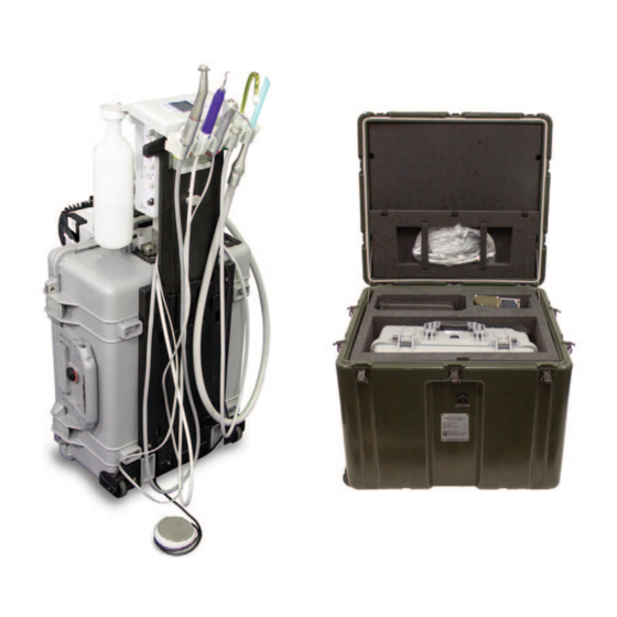
- Page 1 AEU-525CFH-14 Portable Dental System Transport III OPERATION & MAINTENANCE MANUAL...
-
Page 2: Table Of Contents
INDICATIONS FOR USE: for Basic Safety and Essential Performance (Adopted IEC 606011:2005, third edition, 200512), Includes E361057 The AEU-525CFH-14 Transport III is a portable self-contained Corrigendum 1:2011. dental system that is used for endodontic and general dentistry applications. Any malfunction or deterioration in the characteristics and/or performance of this device, as well as any inadequacy in its EXPECTED SERVICE LIFE:... -
Page 3: Introduction
Congratulations! This Transport III System is engineered to provide many years of reliable service. Please read the instructions provided in this manual to receive the best and longest service from your Aseptico equipment. -
Page 4: Safety Precautions
WARNING: Do not install where there is a risk of an explosion. The Transport III System is not intended for operation in the presence of flammable anesthetics or gases. -
Page 5: Setting Up The Unit
LOCKING b. Unhook the waste-tank bungee cord BOTTOM SLOT and remove waste tank. c. Loosen air/electric-module holding strap and remove air/electric module assembly. Also refer to the Aseptico Transport III video at www.aseptico.com for basic setup instructions. - Page 6 SETTING UP THE UNIT - Cont’d setup of the scaler 7. Open the FIG. 6 FIG. 8 SCALER and syringe.) small metal Place scaler and door on the air/water syringe top of the case into their respective and locate the instrument holders high and low VACUUM...
- Page 7 the seals, resulting in poor performance.) 12. Fill the water-supply bottle with clean water or Lock the module into place by hand- other suitable irrigation fluid and attach to the tightening the hold-down thumb-screw on water bottle cap on the left side of the the housing, until snug (Fig 13b).
- Page 8 SETTING UP THE UNIT - Cont’d whole unit. The right-hand switch acts as a the air/electric module (refer to the circuit breaker for the compressor. location-ID label on top of the module). Electrical overloads will trip the two Attach the desired evacuator/saliva ejector switches.
- Page 9 FIG. 21 - AEU-525CFH-14 Transport III - Front View HIGH VOLUME WATER SUPPLY EVACUATOR (HVE) BOTTLE SALIVA EJECTOR WASTE SYRINGE CONTAINER SCALER ELECTRIC MOTOR MANIFOLD PANEL (Pages 14 - 15) ELECTRIC MOTOR CONTROL PANEL (Pages 10-13) SCALER CONTROLS HANDPIECE WATER...
- Page 10 SETTING UP THE UNIT- Cont’d FIG. 22 - AEU-525CFH-14Transport III - Back View WATER BOTTLE PURGE SWITCH AIR/ELECTRIC MODULE ASSEMBLY WATER BOTTLE LOW VACUUM HOSE INSTRUMENT HOLDERS (Page 10) HIGH VACUUM HOSE WASTE CONTAINER HOSE SALIVA LEVEL EJECTOR SENSOR HOSE CORD ASSEMBLY AIR FILTER ASSEMBLY...
- Page 11 FIG. 23 - AEU-525CFH-14 Transport III - Back View WASTE 85% FULL ALERT LED (Page 16) WATER BOTTLE PURGE SWITCH (Page 6) RED LED WASTE SENSOR CONNECTOR AIR FILTER ASSEMBLY POWER ENTRY AND CIRCUIT BREAKER PANEL (Refer to Air Filter Setup Instructions, Page 22)
-
Page 12: Operation Functions
'On' and the instrument removed from its BREAKER (Fig. 24) - Controls power holder before operation can begin. NOTE: On/Off to the Transport III. When the unit is The HVE and saliva ejector are not turned On, the green LED next to the controlled by the Foot Control - they will power switch will illuminate. - Page 13 Fig. 28 -Transport III Electric Motor Control Panel PRESET SELECTOR HANDPIECE RATIO w/DISPLAY SELECTOR w/DISPLAY MOTOR DIRECTION CONTROL PANEL (FWD/REV) SELECTOR STANDBY w/DISPLAY BUTTON ENDODONTIC MODE SPEED (RPM) (ENDO) SELECTOR SELECTOR w/DISPLAY w/DISPLAY TORQUE ILLUMINATION SELECTOR CONTROL w/DISPLAY w/DISPLAY -OR-...
-
Page 14: Customizing Electric Motor Settings
OPERATION FUNCTIONS - Cont'd: 7) Press and release the ILLUMINATION CUSTOMIZING RATIOS: button to turn the hand- The user can enable or disable individual piece LED On/Off. To handpiece ratio options, so that only preferred activate the handpiece or commonly used ratios are displayed during and LED, remove the handpiece from its the ratio selection process. - Page 15 Figure 31 - Factory Default Presets PRESET SPEED ENDO MODE HANDPC DIRECTION TORQUE RATIO (RPM) (8:1 Ratio Only) 200,000 100 % — 150,000 100 % — 150,000 50 % Torque Limit — 100,000 100 % — 100,000 50 % Torque Limit —...
- Page 16 ADJUSTMENT SWITCH then press on the foot pedal. The last used settings will be restored. 6. SCALER (Fig. 32) – The Transport III includes a piezoelectric scaler system that provides adjustable ultrasonic levels and a water coolant system. The scaler includes...
- Page 17 ADJUSTMENT VALVE the black knob on the bottom 9. WATER SUPPLY BOTTLE (Fig. 35) - The of the filter. Transport III incorporates a self-contained BOTTLE IMPORTANT: pressurized water system. The system To open the consists of one 1-liter bottle with a...
- Page 18 Each compartment auxiliary water output using an Aseptico includes its own 85%-full sensor. When fitting (PN AA-60) attached to tubing. The either one of these sensors reaches the...
-
Page 19: Operation
OPERATION: 1. After the Transport III unit has been set up TORQUE - Adjust the up/down TORQUE and you have made yourself familiar with arrows on the display to the desired the operation functions, you are ready for torque. operation as follows: MOTOR DIRECTION - Select either 2. - Page 20 OPERATION - Cont’d 9. Using the HVE and Saliva Ejector b. Screw on a sterile Instrument Tip to the Vacuums: Scaler handpiece and tighten it firmly. Adjust the vacuum pressure on the HVE Turn carefully backwards approximately (high vacuum) and saliva ejector (low 1mm.
-
Page 21: Sterilization & Maintenance
STERILIZATION AND MAINTENANCE: Because of its simple design, the Aseptico Fig. 40 - MOTOR & CORD STERILIZATION AEU-525CFH-14 Transport III System requires very little maintenance. Any The entire motor maintenance that is needed can be & cord assembly performed in minutes. - Page 22 STERILIZATION AND MAINTENANCE - Cont'd: MOTOR LED LENS CLEANING: AIR BOTTLE AND FILTER: The lens of the LED light on the motor (see Routinely check the air bottle filter once a day Fig. 41) is soft and can be damaged. It for condensation (see Fig.
- Page 23 socket as far as it will go. Release ring installer pin, onto the pin’s shank (see and gently tug on tip before using to Figure 43). ensure that tip is securely locked into O-RING FIG.43 socket. Syringe Tip Sterilization: 1) Remove contaminated syringe tip. 2) Remove all visible signs of contamination before autoclaving.
-
Page 24: Air Filter Setup
AIR FILTER SETUP INSTRUCTIONS: Whenever the unit is operated in environments 4. Place Air Filter Assembly, P/N 330634, where dust or other airborne particulates are into the open metal door frame as shown present, it is recommended that the Air Filter in Figure 48. -
Page 25: Repacking Instructions
5. Secure waste tank in place with the tie- CAUTION: down provided. Note “This Side Out” label. BEFORE REPACKING THE TRANSPORT III INTO 6. Strap air/electric module into case as ITS CASE, ALWAYS REMOVE ALL WATER AND shown in Fig. 49 with strap provided. -
Page 26: Troubleshooting
TROUBLESHOOTING: Problem: Correction: Unit will not start: • Check system power connection. • Check if both circuit breaker switches are On. • Check if waste container sensor is connected. • Check if waste container is full. • Check if fan is blocked or inoperative. •... -
Page 27: Replacement Parts List
COMMON REPLACEMENT PARTS LIST ITEM PART NO WASTE TANK ASSEMBLY AEU-525CFH-14 330603 INLINE STRAINER WASTE CONTAINER (HVE STRAINER) 462124 O-RING .125ID X .070CS VT70 (AIR-JUNCTION) 520025 O-RING .320ID X .O28 CS VITON 70 (E-HEAD) 520069 O-RING .042ID X .142 X .050 W VITON (MTR RECEPTCL) 520081 O-RING .208 ID X .070 CS VITON AS568-009 (AIR-JUNCTION) 520121... -
Page 28: Symbol Definitions
SYMBOL DEFINITIONS: Saliva Ejector Type B Equipment Type BF Equipment High Volume Evacuator (HVE) Attention, consult Pressure Gauge accompanying documents Consult Instructions For Use Motor Direction Light Controls Manufacturer Dangerous Voltage Footswitch On/Off Switch - Mains Alternating current Atmospheric Pressure Limitation Temperature Limitation Water Counterclockwise to Increase/Open... -
Page 29: Specifications
SPECIFICATIONS: Transport III Case Size: 17.93” W x 22.06” L x 10.43” H (45.5 cm x 56 cm x 26.5 cm) IMPORTANT Shipping Case Size: 30.5” W x 25.75” L x 24.75” H (77.47 cm x 65.40 cm x 62.86 cm) -
Page 30: Warranty
Aseptico shall be the sole arbiter of such action. In the event of alleged defect under warranty, the purchaser is to notify Aseptico’s Customer Service department promptly. -
Page 31: Notes
NOTES:... - Page 32 P.O. Box 1548 • Woodinville, WA 98072 8333 216th Street SE • Woodinville, WA 98072 (425) 487-3157 • (800) 426-5913 www.aseptico.com • info@aseptico.com P/N: 421231 Rev. E ECO 15748 PRINTED IN 06/2023 THE U.S.A.
Need help?
Do you have a question about the Transport III and is the answer not in the manual?
Questions and answers