
Related Manuals for Aseptico AEU-7000E-70V


Summary of Contents for Aseptico AEU-7000E-70V
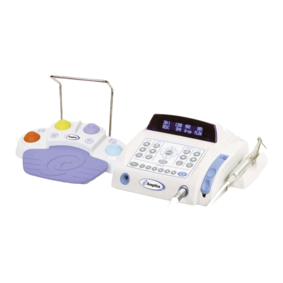
- Page 1 SERVICE MANUAL & PARTS LIST AEU-7000L-70V/7000E-70V Implant/Endodontic Dental Systems AEU-7000L-70V System...
-
Page 2: Table Of Contents
Persons performing repairs to active electronic circuitry or operating High Voltage (e.g. HiPot) test equipment must have training or experience performing similar servicing activities. P.O. Box 1548 • Woodinville, WA 98072-1548 1-800-426-5913 • 425-487-3157 • Fax: 425-487-2608 email: info@aseptico.com • Internet: www.aseptico.com Page i... -
Page 3: General Service Information
(or preset #1 when ordering replacement parts. if the factory setup was recalled). The startup screen will display the Aseptico logo and then the software version Inspection & Operation Verification onboard your 7000L/E unit (see Fig. 4). -
Page 4: Cleaning & Lubrication
GENERAL SERVICE INFORMATION - Cont’d Depress each of the buttons on the AE-70V2 foot control to ESD PRECAUTIONS verify that they control motor direction, turn the pump The following electrostatic controls must be used when On/Off, and step through the torque settings and presets working on this unit: correctly (see Fig. -
Page 5: Disassembly, Top Cover
70V2) from Unit (see Fig. 7). NOTE: The Motor/Cord Assemblies and Foot Control Assembly can be 6. Locate two screws (PN: 510406) and lock washers returned to Aseptico if repair services are necessary -- (PN: 510419) that attach Motor Connector Bracket to consult Aseptico Repair Department for more Chassis (see Fig. - Page 6 DISASSEMBLY - Cont’d Assembly or return Display to Aseptico for repairs. 10. Turn Unit over and position upright on workbench. When installing a new Assembly, ensure that Display Carefully work Top Cover subassembly off Chassis. header is properly oriented to Cover cutout. The...
-
Page 7: Disassembly, Chassis
Control Panel Overlay Assembly is a non-serviceable component of AEU- Assembly 7000L/7000E System. If not functioning properly, either replace with new Assembly or return Pump to Aseptico for repairs.) Figure 15 Pump Cable Connector Figure 13b Overlay Slot Flex Cable... - Page 8 DISASSEMBLY - Cont’d #2 Phillips screwdriver to remove the five screws (PN: Figure 17 510406), lock washers (PN: 510010), and flat washers (PN: 510587) that attach PCB Assembly to the nylon standoffs on Chassis. Remove PCB Assembly and set aside for reuse later (see Fig 16) (NOTE: The PCB Assembly is a non-serviceable component of the AEU- 7000L/7000E System.
- Page 9 Power Inlet Assembly (PN: functioning properly, either replace with a new 840086). Make note of wire/terminal orientation before Assembly or return it to Aseptico for repair.) removing Cables. (NOTE: During reassembly, ensure that the black wire of AC Line-In Cable is attached to 23.
- Page 10 If not functioning properly, either replace with new rubber gasket that is supplied with new Harness Assembly or return PCB to Aseptico for repairs.) Assembly is lost, Flat Washer [PN: 510648] may be substituted. On older model units only, replace rubber 29.
-
Page 11: Reassembly
REASSEMBLY 32. To reassemble the System, perform steps 1-31 above in the reverse order. NOTE: Follow these recommended Steps to reassemble the Top Cover to the Chassis: a. Prior to attaching Top Cover, loosen the two Peristaltic Pump Assembly mounting screws. b. -
Page 12: Final Test Verification
FINAL TEST VERIFICATION 1. Verify fuse values. Fuses should be 1.6A 250V SLO- 8. Connect an AE-70V2 foot control and depress each of BLO (830040). the buttons. Verify that the function of each switch is (from lower left, clockwise): Preset Increment, Motor 2. -
Page 13: Motor Field Testing
Aseptico cursor moves. Use the up (YES) and down (NO) (ref. PN AE-43). The tool needs to be able to grasp keys and verify that the letters change. -
Page 14: Handpiece Calibration Error Testing
HANDPIECE CALIBRATION ERROR TESTING NOTE: This section provides troubleshooting Run” test on either increaser or reduction type procedures for the “Calibration Failed !” error message handpieces. The message “Free Run In Progress / which displays if the AEU-7000L/7000E motor fails Please Wait...”... -
Page 15: Power Pcb Testing
POWER PCB TESTING NOTE: If the power PCB is replaced, the unit’s software If the AEU-7000L/7000E fails to start properly, use this must be reprogrammed (refer to page 19). For flowchart to pinpoint the problem. This flowchart troubleshooting procedures specific to the motor, refer provides additional troubleshooting procedures for the to the motor testing chart on page 12. -
Page 16: Power Pcb Testing Points
48VDC(+/-1.0V). properly the PCB should either be replaced with a c. If 48VDC(+/-1.0V) Supply output is not present, new Assembly or returned to Aseptico for repairs. replace Power Supply. If 48VDC output is present from Supply, replace PCB board. - Page 17 Figure 29A - AEU-7000L Power PCB Test Points Page 15...
- Page 18 Figure 29B - AEU-7000E Power PCB Test Points Page 16...
-
Page 19: Electrical Safety Tests
DC return pin (Pin #4) of the footswitch connector (see Fig. 32). Result is acceptable if the capacitance measured is 5.3-8.0 NOTE: Although Aseptico uses the Associated Research, Inc. Model 7564SA Hipot/Ground Tester IMPORTANT: Any system that fails any of the... -
Page 20: Reprogramming System Software
When the card is ejected, the System will reset with common consumer devices. These cards, available normal power-up screen displayed. from Aseptico, enable a user to update software or 9. Remove the memory card and store it in a safe place. replace existing software that might have been Close the rubber dust cover on the Memory Card accidentally erased or corrupted. -
Page 21: Reprogramming System Firmware
Firmware 7000L & 7000E: PN 890021 (Sold Cards Separately) Contact Aseptico for availability on the latest firmware. Follow the appropriate steps below to reprogram the microcontrollers: Figure 35 A. Master Code Firmware 1. Turn Off all power to the AEU-7000L/E Units. - Page 22 B. Slave Code Firmware Figure 37 1. Turn Off all power to the AEU-7000L/E Units. ‘J1’ 2. Turn Off the programming switch within the AFP-01 Connector Field Programmer (see Fig. 36). 3. Install battery into AFP-01 Field Programmer, as Stepper Motor shown in Figure 36.
-
Page 23: Sterilization Procedure
2) Thoroughly clean the device with a moist cloth or NOTE: Call Aseptico Inc. at 1-800-426-5913 for any towel to remove any remaining signs of debris. questions or clarifications on this sterilization Sterilize procedure. -
Page 24: Maintenance & Cleaning
MAINTENANCE & CLEANING SPECIFICATIONS: Console Dimensions: HANDPIECES - Thorough cleaning and lubrication of 9.98"W x 9.42"L x 5.10"H handpieces after each use and before sterilization is very important to ensure proper operation and service life of the (25.3 cm x 23.9 cm x 12.9 cm) handpiece. -
Page 25: General Troubleshooting
GENERAL TROUBLESHOOTING: Problem: Correction: Console does not light when turned on: • Check console to power connection. • Check fuse. If blown, replace with 1.6A/250V slo-blow fuse. • Check motor plug connection. Console lights when turned on, but handpiece does not turn: •... -
Page 26: Aeu-7000L Parts List
Page 24... - Page 27 Figure 43 - AEU-7000L PARTS Page 25...
-
Page 28: Aeu-7000E Parts List
Page 26... - Page 29 Figure 44 - AEU-7000E PARTS Page 27...
-
Page 30: Symbol Definitions
NOTE: The above hand tools are US standard (non-metric) and can be procured locally. The Hi-Pot Tester used is the Associated Research 7564SA. Alternative testers should have specifications equivalent to the Associated Research Model 7564SA Dielectric Tester/Analyzer. To procure the Reprogramming Memory Card with latest Software, contact Aseptico. Page 28... -
Page 31: Warranty
Aseptico repairs carry a ninety (90) day limited warranty against defects in material and workmanship. This warranty pertains only to the specific repair. Any new and different defect in materials or workmanship will be treated as a new repair. If the product is not covered under warranty, Aseptico offers Repair Services for a fee. NOTES... - Page 32 For Further Service And/Or Technical Assistance Contact: P.O. Box 1548 • 8333 216th Street SE Woodinville, WA 98072-1548 1-800-426-5913 • 425-487-3157 • Fax: 425-487-2608 Internet: www.aseptico.com • Email: info@aseptico.com P/N: 420915 Rev. G ECO 14673 PRINTED IN THE USA 03/2019...
Need help?
Do you have a question about the AEU-7000E-70V and is the answer not in the manual?
Questions and answers